
Related Manuals for Miller Electric Regency 250


Summary of Contents for Miller Electric Regency 250
- Page 1 OM-293 120 243N October 2001 Processes MIG (GMAW) Welding Description Arc Welding Power Source Regency 250 Visit our website at www.MillerWelds.com...
- Page 2 ISO 9001 Quality System Standard. Warranty and service information for your particular model are also provided. Miller Electric manufactures a full line of welders and welding related equipment. For information on other quality Miller products, contact your local Miller distributor to receive the latest full line catalog or individual catalog sheets.
-
Page 3: Table Of Contents
SECTION 1 – SAFETY PRECAUTIONS - READ BEFORE USING 1-1. Symbol Usage 1-2. Arc Welding Hazards 1-3. Additional Symbols for Installation, Operation, and Maintenance WARNING 1-4. Principal Safety Standards 1-5. EMF Information This product, when used SECTION 1 – CONSIGNES DE SECURITE – LIRE AVANT UTILISATION for welding or cutting, 1-1. -
Page 5: Section 1 - Safety Precautions - Read Before Using
SECTION 1 – SAFETY PRECAUTIONS - READ BEFORE USING 1-1. Symbol Usage Means Warning! Watch Out! There are possible hazards with this procedure! The possible hazards are shown in the adjoining symbols. Y Marks a special safety message. Means “Note”; not safety related. 1-2. - Page 6 ARC RAYS can burn eyes and skin. Arc rays from the welding process produce intense visible and invisible (ultraviolet and infrared) rays that can burn eyes and skin. Sparks fly off from the weld. D Wear a welding helmet fitted with a proper shade of filter to protect your face and eyes when welding or watching (see ANSI Z49.1 and Z87.1 listed in Safety Standards).
-
Page 7: Additional Symbols For Installation, Operation, And Maintenance
1-3. Additional Symbols For Installation, Operation, And Maintenance FIRE OR EXPLOSION hazard. D Do not install or place unit on, over, or near combustible surfaces. D Do not install unit near flammables. D Do not overload building wiring – be sure power supply system is properly sized, rated, and protected to handle this unit. -
Page 8: Emf Information
1-5. EMF Information Considerations About Welding And The Effects Of Low Frequency Electric And Magnetic Fields Welding current, as it flows through welding cables, will cause electro- magnetic fields. There has been and still is some concern about such fields. However, after examining more than 500 studies spanning 17 years of research, a special blue ribbon committee of the National Research Council concluded that: “The body of evidence, in the committee’... -
Page 9: Section 1 - Consignes De Securite - Lire Avant Utilisation
SECTION 1 – CONSIGNES DE SECURITE – LIRE AVANT 1-1. Signification des symboles Signifie Mise en garde ! Soyez vigilant ! Cette procédure présente des risques de danger ! Ceux-ci sont identifiés par des symboles adjacents aux directives. Y Identifie un message de sécurité particulier. Signifie NOTA ;... - Page 10 LES RAYONS DE L’ARC peuvent pro- voquer des brûlures dans les yeux et sur la peau. Le rayonnement de l’arc du procédé de soudage génère des rayons visibles et invisibles intenses (ultraviolets et infrarouges) susceptibles de provoquer des brûlures dans les yeux et sur la peau. Des étincelles sont projetées pendant le soudage.
-
Page 11: Dangers Supplémentaires En Relation Avec L'installation, Le Fonctionnement Et La Maintenance
1-3. Dangers supplémentaires en relation avec l’installation, le fonctionnement et la maintenance Risque D’INCENDIE OU D’EXPLOSION. D Ne pas placer l’appareil sur, au-dessus ou à proxi- mité de surfaces infllammables. D Ne pas installer l’appareil à proximité de produits inflammables D Ne pas surcharger l’installation électrique –... -
Page 12: Principales Normes De Sécurité
1-4. Principales normes de sécurité Safety in Welding and Cutting, norme ANSI Z49.1, de l’American Wel- ding Society, 550 N.W. Lejeune Rd, Miami FL 33126 Safety and Health Sandards, OSHA 29 CFR 1910, du Superintendent of Documents, U.S. Government Printing Office, Washington, D.C. 20402. -
Page 13: Section 2 - Installation
SECTION 2 – INSTALLATION 2-1. Specifications Rated Welding Voltage Range Output Low Range: 10–20 200 A @ 28 Volts DC, V; High Range: 60% Duty Cycle 20–30 V *While idling 2-2. Duty Cycle And Overheating 6 Minutes Welding Overheating Amperes Input at Rated Load Maximum Open- Output, 60 Hz, Single-Phase Circuit Voltage DC... -
Page 14: Volt-Ampere Curves
2-3. Volt-Ampere Curves 2-4. Selecting A Location Movement Location And Airflow Tools Needed: 3/8 in 18 in (460 mm) OM-293 Page 10 Volt-ampere curves show mum and maximum voltage and amperage output capabilities of unit. Curves of other settings fall be- tween curves shown. -
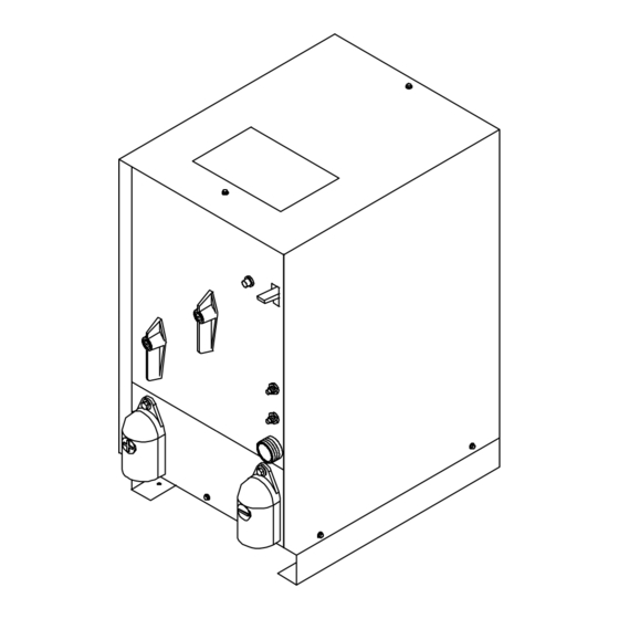
Page 15: Dimensions And Weights
2-5. Dimensions And Weights H 8 Holes Front 2-6. Weld Output Terminals And Selecting Cable Sizes Weld Output Welding Terminals Amperes Positive Negative (–) Ref. 121 470-E Weld cable size (AWG) is based on either a 4 volts or less drop or a current density of at least 300 circular mils per ampere. 155 897-A Total Cable (Copper) Length In Weld Circuit Not Exceeding 150 ft... -
Page 16: Remote 14 Receptacle Information
2-7. Remote 14 Receptacle Information C L N Ref. 121 470-E / Ref. 192 412 *The remaining sockets are not used. 2-8. Electrical Service Guide Input Voltage Input Amperes At Rated Output Max Recommended Standard Fuse Rating In Amperes Time-Delay Normal Operating 3 Min Input Conductor Size In AWG/Kcmil Max Recommended Input Conductor Length In Feet (Meters) -
Page 17: Placing Jumper Links And Connecting Input Power
2-9. Placing Jumper Links And Connecting Input Power 200V 230V Tools Needed: 3/8 in 460V S-153 408-A Check input voltage available at site. Jumper Link Label Jumper Link Move jumper links to match input power. Line Disconnect Device Select type and size of overcurrent protection using Section 2-8. -
Page 18: Section 3 - Operation
SECTION 3 – OPERATION 3-1. Controls Voltage Range Switch Use switch to select voltage range. Voltage Adjustment Switch Use switch to adjust voltage within range se- lected by Voltage Range switch. Each posi- tion of the switch is a change of 2 volts. OM-293 Page 14 Y Do not change position of Voltage Range switch or Voltage Adjustment... -
Page 19: Section 4 - Maintenance & Troubleshooting
SECTION 4 – MAINTENANCE & TROUBLESHOOTING 4-1. Routine Maintenance Y Disconnect power before maintaining. Unreadable 4-2. Troubleshooting Trouble No weld output; unit completely inoperative; pilot light not on. Erratic weld output. No open-circuit voltage; pilot light on; wire does not feed. -
Page 20: Section 5 - Electrical Diagram
SECTION 5 – ELECTRICAL DIAGRAM 192 974 Figure 5-1. Circuit Diagram For Welding Power Source OM-293 Page 16... -
Page 21: Section 6 - Parts List
SECTION 6 – PARTS LIST Hardware is common and not available unless listed. (Fig 6–2)–19 Item Dia. Part Mkgs....+047 167 .. - Page 22 Hardware is common and not available unless listed. OM-293 Page 18 Figure 6-2. Panel, Front w/Components 121 587-G...
- Page 23 Item Dia. Part Mkgs....206 444 ....192 973 .
- Page 24 Item Dia. Part Mkgs....081 372 ....172 529 .
- Page 27 Warranty Questions? Call LIMITED WARRANTY – Subject to the terms and conditions below, Miller Electric Mfg. Co., Appleton, Wisconsin, warrants 1-800-4-A-MILLER to its original retail purchaser that new Miller equipment sold for your local after the effective date of this limited warranty is free of defects in material and workmanship at the time it is shipped by Miller.
-
Page 28: Options And Accessories
Parts) Circuit Diagrams Welding Process Handbooks File a claim for loss or damage during shipment. 2002 Miller Electric Mfg. Co. 1/02 Miller Electric Mfg. Co. An Illinois Tool Works Company 1635 West Spencer Street Appleton, WI 54914 USA International Headquarters–USA USA Phone: 920-735-4505 Auto-Attended USA &...