Table of Contents
Advertisement
OWNER'S MANUAL
IMPORTANT: Read and understand the entire contents of both this manual
and the power source manual used with this unit, with special emphasis on
the safety material throughout both manuals, before installing, operating, or
maintaining this equipment. This unit and these instructions are for use only
by persons trained and experienced in the safe operation of welding equip-
ment. Do not allow untrained persons to install, operate, or maintain this unit.
Contact your distributor if you do not fully understand these instructions.
SA-141 127
February 1992
FORM: OM-823G
Effective With Serial No. KB055102
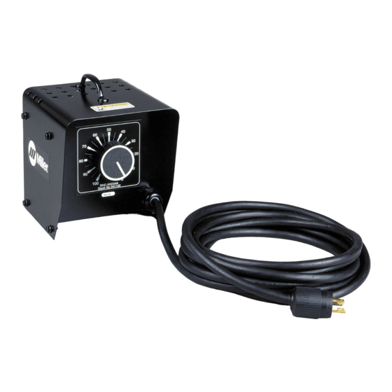
MODEL: RHC-3
RHC-3-2
RHC-3GD9A
RHC-3GD25B
RHCS-3
RHC-3-GD34A
RHC-14
RHC-23
MILLER ELECTRIC Mfg. Co.
A Miller Group Ltd., Company
P.O. Box 1079
Appleton, WI 54912 USA
Tel. 414-734-9821
PRINTED IN U.S.A.
Advertisement
Table of Contents

Summary of Contents for Miller Electric RHC-14
- Page 1 SA-141 127 February 1992 FORM: OM-823G Effective With Serial No. KB055102 MODEL: RHC-3 RHC-3-2 RHC-3GD9A RHC-3GD25B RHCS-3 RHC-3-GD34A RHC-14 RHC-23 MILLER ELECTRIC Mfg. Co. A Miller Group Ltd., Company P.O. Box 1079 Appleton, WI 54912 USA Tel. 414-734-9821 PRINTED IN U.S.A.
-
Page 3: Table Of Contents
Diagram 5-3. Circuit Diagram For RHC-3-GD9A And RHC-3-GD34A Diagram 5-4. Circuit Diagram For RHC-3-GD25B Diagram 5-5. Circuit Diagram For RHC-14 And RHC-23 SECTION 6 − PARTS LIST Figure 6-1. Complete Assembly (RHC-3 Illustrated) Table 2-1. Cord Conductor Length And Size RECEIVING-HANDLING Use the following spaces to record the Model Designa- tion and Serial or Style Number of your unit. -
Page 4: Section 1 − Safety Precautions And Signal Words
SECTION 1 − SAFETY PRECAUTIONS AND SIGNAL WORDS 1-1. GENERAL INFORMATION AND SAFETY A. General Information presented in this manual and on various la- bels, tags, and plates on the unit pertains to equipment design, installation, operation, maintenance, and troubleshooting which should be read, understood, and followed for the safe and effective use of this equipment. -
Page 5: Section 3 − Operator Controls
Remote position for proper remote control operation. The RHC-14 or RHC-23 switch has two positions, ON and OFF. Placing this switch in the ON position provides open-circuit voltage. Placing this switch in the OFF posi- tion stops open-circuit voltage (ocv goes to zero). -
Page 6: Section 5 − Electrical Diagrams
SECTION 5 − ELECTRICAL DIAGRAMS Circuit Diagram No. SA-150 670 Diagram 5-1. Circuit Diagram For Remote Hand Control Used With Transformer Arc Welding Power Source Circuit Diagram No. SA-150 671 Diagram 5-2. Circuit Diagram For RHCS-3 Circuit Diagram No. SA-094 231-A Diagram 5-3. -
Page 7: Diagram 5-4. Circuit Diagram For Rhc-3-Gd25B
Circuit Diagram No. SA-094 232-A Diagram 5-4. Circuit Diagram For RHC-3-GD25B Circuit Diagram No. SA-053 656-A Diagram 5-5. Circuit Diagram For RHC-14 And RHC-23 OM-823 Page 4... -
Page 8: Section 6 − Parts List
SECTION 6 − PARTS LIST OM-823 Page 5... - Page 9 Item Dia. Part Description Mkgs. Figure 6-1. Complete Assembly 030 653 RHEOSTAT, WW 150W 15 ohm 107 363 RHEOSTAT, WW 150W 15 ohm 035 897 POTENTIOMETER, C sltd sft 1/T 2W 1000 ohm 039 272 RHEOSTAT, WW 150W 1250 ohm .
- Page 10 Item Dia. Part Description Mkgs. Complete Assembly (Use Fig 6-1 View) . . . 005 355 RHEOSTAT, WW 50W 9 ohm . . . 605 049 RHEOSTAT, WW 300W 25 ohm . . . 605 960 RHEOSTAT, WW 300W 34 ohm .


