
Related Manuals for Miller Electric CST 250


Summary of Contents for Miller Electric CST 250
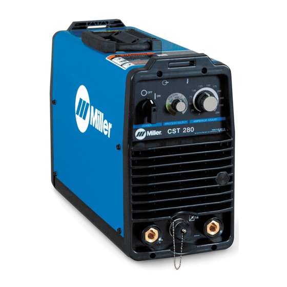
- Page 1 Visit our website at www.MillerWelds.com OM-2237 July 2005 Processes Description Arc Welding Power Source CST 250 206 035H Stick (SMAW) Welding TIG (GTAW) Welding...
- Page 2 ISO 9001:2000 Quality System Standard. particular model are also provided. Miller Electric manufactures a full line of welders and welding related equipment. For information on other quality Miller products, contact your local Miller distributor to receive the latest full line catalog or individual catalog sheets.
-
Page 3: Table Of Contents
TABLE OF CONTENTS SECTION 1 − SAFETY PRECAUTIONS - READ BEFORE USING 1-1. Symbol Usage ............... 1-2. -
Page 5: Section 1 − Safety Precautions - Read Before Using
SECTION 1 − SAFETY PRECAUTIONS - READ BEFORE USING 1-1. Symbol Usage Means Warning! Watch Out! There are possible hazards with this procedure! The possible hazards are shown in the adjoining symbols. Y Marks a special safety message. Means “Note”; not safety related. 1-2. - Page 6 D Do not use welder to thaw frozen pipes. D Remove stick electrode from holder or cut off welding wire at contact tip when not in use.
-
Page 7: Additional Symbols For Installation, Operation, And Maintenance
1-3. Additional Symbols For Installation, Operation, And Maintenance FIRE OR EXPLOSION hazard. D Do not install or place unit on, over, or near combustible surfaces. D Do not install unit near flammables. D Do not overload building wiring − be sure power supply system is properly sized, rated, and protected to handle this unit. -
Page 8: Principal Safety Standards
1-5. Principal Safety Standards Safety in Welding, Cutting, and Allied Processes, ANSI Standard Z49.1, from American Welding Society, 550 N.W. LeJeune Rd, Miami FL 33126 (phone: 305-443-9353, website: www.aws.org). Recommended Safe Practices for the Preparation for Welding and Cut- ting of Containers and Piping, American Welding Society Standard AWS F4.1, from American Welding Society, 550 N.W. -
Page 9: Section 2 − Consignes De Sécurité − À Lire Avant Utilisation
SECTION 2 − CONSIGNES DE SÉCURITÉ − À LIRE AVANT 2-1. Signification des symboles Signifie « Mise en garde. Faire preuve de vigilance. » Cette procédure présente des risques identifiés par les symboles adjacents aux directives. Y Identifie un message de sécurité particulier. Signifie «... - Page 10 LES RAYONS DE L’ARC peuvent cau- ser des brûlures oculaires et cuta- nées. Le rayonnement de l’arc génère des rayons visibles et invisibles intenses (ultraviolets et infrarouges) suscep- tibles de causer des brûlures oculaires et cutanées. Des étincelles sont projetées pendant le soudage. D Porter un masque de soudage muni d’un filtre de la nuance adéquate pour se protéger le visage et les yeux pendant le soudage ou pour re- garder (voir les normes de sécurité...
-
Page 11: Autres Symboles Relatifs À L'installation, Au Fonctionnement Et À L'entretien De L'appareil
2-3. Autres symboles relatifs à l’installation, au fonctionnement et à l’entretien de l’appareil. Risque D’INCENDIE OU D’EXPLO- SION D Ne pas placer l’appareil sur une surface inflam- mable, ni au−dessus ou à proximité d’elle. D Ne pas installer l’appareil à proximité de produits inflammables. D Ne pas surcharger l’installation électrique −... -
Page 12: Principales Normes De Sécurité
2-4. Principales normes de sécurité Safety in Welding, Cutting, and Allied Processes, norme ANSI Z49.1, de l’American Welding Society, 550 N.W. LeJeune Rd, Miami FL 33126 (téléphone : (305) 443−9353, site Web : www.aws.org). Recommended Safe Practices for the Preparation for Welding and Cut- ting of Containers and Piping, norme American Welding Society AWS F4.1, de l’American Welding Society, 550 N.W. -
Page 13: Section 3 − Installation
SECTION 3 − INSTALLATION 3-1. Specifications Welding Input Rated Welding Mode Power Output Amperage Range Range 250 A @ 30 VDC, 50 % Duty Cycle 3-Phase 3-Phase 5-250 A 5-250 A 200 A @ 28 VDC, 100 % Duty Cycle Stick Stick (SMAW) -
Page 14: Stick (Smaw) Volt-Ampere Curves
3-3. Stick (SMAW) Volt-Ampere Curves 100A SOFT 100A SOFT 100A STIFF 150A SOFT OM-2237 Page 10 xx10 Stick VA Curves DC AMPS 100A STIFF 150A STIFF 200A STIFF 150A SOFT 200A SOFT 250A SOFT xx18 Stick VA Curve DC AMPS 150A STIFF 200A STIFF 250A STIFF... -
Page 15: Tig (Gtaw) Volt-Ampere Curve
3-4. TIG (GTAW) Volt-Ampere Curve TIG VA Curve Amps Volt-ampere curves show minimum maximum voltage amperage output capabilities of welding power source. Curves of other settings fall between curves shown. 100A 150A 200A Ref. 206174 OM-2237 Page 11... -
Page 16: Selecting A Location
3-5. Selecting A Location Dimensions And Weight 40 lb (18.2 kg) - with power cord 7-1/2 in (191 mm) Location And Airflow 18 in (460 mm) OM-2237 Page 12 18 in (457 mm) 13-1/2 in (343 mm) 18 in (460 mm) Line Disconnect Device Locate unit near correct input power supply. -
Page 17: Weld Output Terminals And Selecting Cable Sizes
3-6. Weld Output Terminals And Selecting Cable Sizes* Weld Output Welding Terminals Amperes*** − Output Receptacles This chart is a general guideline and may not suit all applications. If cable overheating occurs (normally you can smell it), use next size larger cable. -
Page 18: Tig Lift-Arct Dcen (Direct Current Electrode Negative) Connections
3-7. TIG Lift-Arct DCEN (Direct Current Electrode Negative) Connections OM-2237 Page 14 Positive (+) Weld Output Terminal Connect work lead to positive weld output terminal. Negative (−) Weld Output Terminal Connect TIG torch to negative weld output terminal. Gas Cylinder Cylinder Valve Open valve slightly so gas flow blows dirt from valve. -
Page 19: Stick Dcep (Direct Current Electrode Positive) Connections
3-8. Stick DCEP (Direct Current Electrode Positive) Connections 3-9. Electrical Service Guide CAUTION: INCORRECT INPUT POWER can damage this welding power source. This welding power source requires a CONTINUOUS supply of 50/60 Hz power at +10% of rated input voltage. Do not use a generator with automatic idle device (that idles engine when no load is sensed) to supply input power to this welding power source. -
Page 20: Selecting 230 Volts Ac Single/Three Phase Input Voltage
3-10. Selecting 230 Volts AC Single/Three Phase Input Voltage Tools Needed: 5/16 in OM-2237 Page 16 3 Top Cover Securing Screws — Left And Right Side Panel 2 Top Cover Securing Screws — Front And Rear Panel Y Turn Off welding power source, disconnect input... -
Page 21: Selecting 460 - 575 Volts Ac Three Phase Input Voltage
3-11. Selecting 460 - 575 Volts AC Three Phase Input Voltage Tools Needed: 5/16 in 3 Top Cover Securing Screws — Left And Right Side Panel 2 Top Cover Securing Screws — Front And Rear Panel Y Turn Off welding power source, disconnect input... -
Page 22: Connecting Input Power
3-12. Connecting Input Power Green Or Green/Yellow = GND/PE OM-2237 Page 18 Green Or Green/Yellow Y Always connect grounding conductor first Green or Green/Yellow Y Disconnect and lockout/tag- out input power before connecting input conduc- tors from unit. Y Have only qualified persons make this installation. -
Page 23: Section 4 − Operation
SECTION 4 − OPERATION 4-1. Controls NOTE: Green on nameplate indicates a TIG function, Gray indicates a Stick function. Power Switch Use switch to turn unit and indicator light On/Off. Output Indicator Light When unit is first energized this indicator light flashes several times and then illuminates continuously. -
Page 24: Process Select Control
4-2. Process Select Control RECOMMENDED PROCESS SELECTIONS VS ELECTRODE TYPE ELECTRODE TYPE EXXX1 EXXX2 EXXX3 EXXX4 EXXX5 EXXX6 EXXX7 EXXX8 STAINLESS OM-2237 Page 20 SUGGESTED PROCESS SETTING EXX10 EXX10 EXX18 EXX18 EXX18 EXX18 EXX18 EXX18 EXX18 Process Select Control Rotate knob to select desired process. -
Page 25: Stick Start Procedure − Scratch Start Technique
4-3. Stick Start Procedure − Scratch Start Technique 4-4. Lift-Arc Start Procedure Lift-Arc Start Method “Touch” Do NOT Strike Like A Match! 1 − 2 Seconds With Stick selected, start arc as follows: Electrode Workpiece Drag electrode across workpiece like striking a match;... -
Page 26: Amperage Control
4-5. Amperage Control 4-6. Remote 14 Receptacle Information This unit automatically senses when a remote control is connected to the remote 14 receptacle. After connecting a remote control, the unit will automatically adjust output control to a primary/secondary configuration. In this configuration, the AMP ADJUST control on the unit becomes the primary and sets the maximum amperage output of the unit. -
Page 27: Section 5 − Maintenance And Troubleshooting
SECTION 5 − MAINTENANCE AND TROUBLESHOOTING 5-1. Routine Maintenance 3 Months Replace unreadable labels. 3 Months Repair Or Replace Cracked Cables And Cords 6 Months Y Do not remove case when 5-2. Blowing Out Inside Of Unit Y Disconnect power before maintaining. Maintain more often during severe conditions. -
Page 28: Troubleshooting
5-3. Troubleshooting Trouble No weld output; unit completely Line disconnect switch open. inoperative. Blown line fuse(s). Improper input power connections. No weld output. Line voltage too high or too low. Blue LED flashes continuously yellow Blue LED flashes continuously, yellow LED off. - Page 29 Trouble Erratic or improper weld output. Weld cable too small or defective. Dirty or loose connections. Improper size tungsten. Wandering arc Worn or defective tungsten. Shielding gas flow too high. Shielding gas blown away from weld Tungsten electrode oxidizing and not zone.
-
Page 30: Section 6 − Electrical Diagrams
SECTION 6 − ELECTRICAL DIAGRAMS Figure 6-1. Circuit Diagram 206 171-C OM-2237 Page 26... -
Page 31: Section 7 − Selecting And Preparing Tungsten Electrode
SECTION 7 − SELECTING AND PREPARING TUNGSTEN NOTE For additional information, see your distributor for a handbook on the Gas Tungsten Arc Welding (GTAW) process.Wear clean gloves to prevent contamination of tungsten electrode. 7-1. Selecting Tungsten Electrode Electrode Diameter DC − Argon − Electrode Negative/Straight Polarity 2% Thorium Alloyed Tungsten (Red Band) -
Page 32: Preparing Tungsten For Ac Or Dc Electrode Negative (Dcen) Welding
7-3. Preparing Tungsten For AC Or DC Electrode Negative (DCEN) Welding Ideal Tungsten Preparation − Stable Arc Wrong Tungsten Preparation − Wandering Arc OM-2237 Page 28 2-1/2 Times Electrode Diameter Tungsten Electrode Tapered End Grind end of tungsten on fine grit, hard abrasive wheel before weld- ing. - Page 33 Notes OM-2237 Page 29...
-
Page 34: Section 8 − Parts List
SECTION 8 − PARTS LIST OM-2237 Page 30 Figure 8-1. Main Assembly Hardware is common and not available unless listed. 803 157-B... - Page 35 Item Part Figure 8-1. Main Assembly ... . . 205758 PANEL,FRONT W/CMPNT ... . . 205780 PANEL,REAR W/CMPNT ..
- Page 36 ....... . NAMEPLATE,MILLER CST 250 ......
- Page 37 Hardware is common and not available unless listed. Item Part Figure 8-3. Panel, Rear w/Components ... . . 194242 PANEL,FRONT/REAR ... . . 206052 PANEL,REAR UPPER .
- Page 38 Hardware is common and not available unless listed. Item Diagram Part marking Figure 8-4. Magnetics Subassembly ... . . 206063 PANEL,PLENUM ..206065 XFMR,HF LITZ/LITZ W/BOOST .
- Page 39 Hardware is common and not available unless listed. Figure 8-5. Heat Sink Assembly, Output Diode Item Diagram Part marking Figure 8-5. Heat Sink Assembly, Output Diode ... . . 205916 HEAT SINK,DIODE OUTPUT .
- Page 40 Hardware is common and not available unless listed. Item Diagram Part marking Figure 8-6. Base Assembly ... . . 206089 BASE, ... . . 019663 MOUNT,NPRN 15/16ODX3/8REC 3/16X3/8 .
- Page 41 Hardware is common and not available unless listed. Item Diagram Part marking Figure 8-7. Heat Sink Assembly, Input ... . . 205915 HEAT SINK,IGBT/INPUT RECTIFIER MODULE ... . . 206091 BRACKET,HEATSINK REAR .
- Page 42 Notes...
- Page 43 Warranty Questions? Call LIMITED WARRANTY − Subject to the terms and conditions below, Miller Electric Mfg. Co., Appleton, Wisconsin, warrants to 1-800-4-A-MILLER its original retail purchaser that new Miller equipment sold after for your local the effective date of this limited warranty is free of defects in material and workmanship at the time it is shipped by Miller.
-
Page 44: Options And Accessories
File a claim for loss or damage during shipment. For assistance in filing or settling claims, contact your distributor and/or equipment manufacturer’s Transportation Department. 2005 Miller Electric Mfg. Co. 1/05 Miller Electric Mfg. Co. An Illinois Tool Works Company 1635 West Spencer Street Appleton, WI 54914 USA International Headquarters−USA...