
Related Manuals for Miller Electric ProHeat 35


Summary of Contents for Miller Electric ProHeat 35
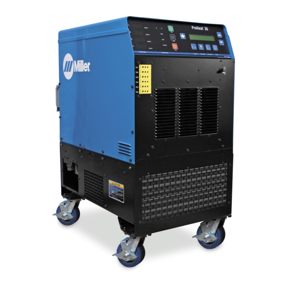
- Page 1 OM-222 166K 2007−11 Processes Induction Heating Description Induction Heating Power Source ProHeat 35 Visit our website at File: Induction Heating www.MillerWelds.com...
- Page 2 ISO 9001:2000 Quality System Standard. particular model are also provided. Miller Electric manufactures a full line of welders and welding related equipment. For information on other quality Miller products, contact your local Miller distributor to receive the latest full line catalog or individual specification sheets.
-
Page 3: Table Of Contents
TABLE OF CONTENTS SECTION 1 − SAFETY PRECAUTIONS − READ BEFORE USING 1-1. Symbol Usage ............... . 1-2. - Page 4 TABLE OF CONTENTS 6-5. Run Status ................6-5-1.
- Page 5 Declaration of Conformity for European Community (CE) Products This information is provided for units with CE certification (see rating label on unit). Manufacturer: Miller Electric Mg. Co. 1635 W. Spencer St. Appleton, WI 54914 USA Phone: (920) 734-9821 European Contact Signature:...
-
Page 7: Section 1 − Safety Precautions − Read Before Using
SECTION 1 − SAFETY PRECAUTIONS − READ BEFORE USING Protect yourself and others from injury — read and follow these precautions. 1-1. Symbol Usage DANGER! − Indicates a hazardous situation which, if not avoided, will result in death or serious injury. The possible hazards are shown in the adjoining symbols or explained in the text. -
Page 8: Additional Symbols For Installation, Operation, And Maintenance
FIRE OR EXPLOSION hazard. D Do not overheat parts. D Watch for fire; keep extinguisher nearby. D Keep flammables away from work area. Do not locate unit on, over, or near combustible surfaces. Do not install unit near flammables. Do not operate where the atmosphere may contain flammable dust, gas, or liquid vapors (such as gasoline). -
Page 9: Principal Safety Standards
1-5. Principal Safety Standards Safety in Welding, Cutting, and Allied Processes, ANSI Standard Z49.1, from Global Engineering Documents (phone: 1-877-413-5184, website: www.global.ihs.com). OSHA, Occupational Safety and Health Standards for General Industry, Title 29, Code of Federal Regulations (CFR), Part 1910, Subpart Q, and Part 1926, Subpart J, from U.S. -
Page 10: Section 2 − Consignes De Sécurité − Lire Avant Utilisation
SECTION 2 − CONSIGNES DE SÉCURITÉ − LIRE AVANT Se protéger, ainsi que toute autre personne travaillant sur les lieux, contre les étincelles et le métal chaud. 2-1. Signification des symboles DANGER! − Indique une situation dangereuse qui si on l’évite pas peut donner la mort ou des blessures graves. -
Page 11: Dangers Supplémentaires En Relation Avec L'installation, Le Fonctionnement Et La Maintenance
À l’intérieur, ventiler la zone et/ou utiliser une ventilation forcée au niveau de l’arc pour l’évacuation des fumées et des gaz. Si la ventilation est médiocre, porter un respirateur anti-vapeurs ap- prouvé. Lire et comprendre les spécifications de sécurité des matériaux (MSDS) et les instructions du fabricant concernant les adhésifs, les flux, les métaux, les consommables, les revêtements, les nettoyants et les dégraisseurs. -
Page 12: Proposition Californienne 65 Avertissements
LE RAYONNEMENT HAUTE FRÉ- QUENCE (HF) risque de provoquer des interférences. D Le rayonnement haute fréquence (HF) peut provoquer des interférences avec les équipe- ments de radio-navigation et de communication, les services de sécurité et les ordinateurs. Demander seulement à des personnes qualifiées familiarisées avec des équipements électroniques de faire fonctionner l’installa- tion. -
Page 13: Section 3 − Definitions
SECTION 3 − DEFINITIONS 3-1. Warning Label Definitions Warning! Watch Out! There are possible hazards as shown by the symbols. Electric shock from wiring can kill. 1.1 Wear dry insulating gloves. Do not wear wet or damaged gloves. 1.2 Disconnect input plug or power before working on machine. -
Page 14: Warning Label Definitions (Continued)
3-2. Warning Label Definitions (Continued) OM-222 166 Page 8 Warning! Watch Out! There are possible hazards as shown by the symbols. Electric shock from wiring can kill. Overuse can cause overheating. Follow rated duty cycle. Disconnect input plug or power before working on machine. -
Page 15: Rating Label For Ce Products
3-3. Rating Label For CE Products For label location see Section 4-2. 226 534-B 3-4. WEEE Label (For Products Sold Within The EU) Do not discard product (where ap- plicable) with general waste. Reuse or recycle Waste Electrical and Electronic Equipment (WEEE) by disposing at a designated collec- tion facility. -
Page 16: Symbols And Definitions
3-5. Symbols And Definitions Some symbols are found only on CE products. Amperes Degree Of Protection Increase Primary Voltage Rated Maximum Supply Current 1max 1max Remote SECTION 4 − INSTALLATION 4-1. Specifications Rated Output Output Frequency Frequency Single Dual Output Output 35 kW At 35 kW At... -
Page 17: Selecting A Location
4-2. Selecting A Location Movement Location And Airflow 12 in (305 mm) 18 in (460 mm) 4-3. Tipping (460 mm) 12 in (305 mm) Lifting Eye Lifting Forks Use lifting eye or lifting forks to move unit. If using lifting forks, extend forks beyond opposite side of unit. -
Page 18: Electrical Service Guide
4-4. Electrical Service Guide Failure to follow these electrical service guide recommendations could create an electric shock or fire hazard. These recommenda- tions are for a dedicated branch circuit sized for the rated output and duty cycle of the welding power source. Input Voltage Input Amperes At Rated Output Max Recommended Standard Fuse Or Circuit Breaker Rating In Amperes... -
Page 19: Connecting 3-Phase Input Power For 460/575 Volt Models
4-5. Connecting 3-Phase Input Power For 460/575 Volt Models Tools Needed: 3/8 in GND/PE Earth Ground 803 994-C Installation must meet all National and Local Codes − have only quali- fied persons make this installation. Disconnect and lockout/tagout in- put power before connecting input conductors from unit. -
Page 20: Connecting 3-Phase Input Power For 400/460 Volt Models
4-6. Connecting 3-Phase Input Power For 400/460 Volt Models Tools Needed: Installation must meet all National and Local Codes − have only qualified per- sons make this installation. Disconnect and lockout/tagout input power before connecting input con- ductors from unit. Make input power connections to the welding power source first. -
Page 21: Power Source Output Connections
4-7. Power Source Output Connections Single Air-Cooled Output Connection Output Connector 1 Output Connector 2 Protective Plug Air-Cooled Extension Cable Liquid-Cooled Extension Cable The power source is capable of single or dual output. When connected for single power output, up to 35 kW is available at the single output connection. -
Page 22: Remote 14 Receptacle Rc14 Information And Connections
4-8. Remote 14 Receptacle RC14 Information and Connections 4-9. Remote 14 Socket Information Socket Remote Contactor Remote Contactor Remote Output Control Remote Output Control F, J Power Source Limit Remote Metering Remote Metering OM-222 166 Page 16 C L N Socket Information +24 volts dc. -
Page 23: Temperature Recorder Receptacle Rc9 Information And Connections
4-10. Temperature Recorder Receptacle RC9 Information And Connections 4-11. Temperature Recorder Socket Information Socket No. Socket Information Thermocouple No. 1 (TC1), 0-10 volt dc signal [0V = −50° F (−46° C), 10V = 1500° F (816° C)] Thermocouple No. 2 (TC2), 0-10 volt dc signal [0V = −50° F (−46° C), 10V = 1500° F (816° C)] Thermocouple No. -
Page 24: Secondary Insulation Protection
4-12. Secondary Insulation Protection OM-222 166 Page 18 Secondary insulation protection circuitry automatically shuts down the power source output if a potentially hazardous condition exists heating device connected to the power source (e.g. insulation has broken down on a heating blanket causing conductor to come into contact with... -
Page 25: 115 Volt Ac Duplex Receptacle And Supplementary Protector
4-13. 115 Volt AC Duplex Receptacle And Supplementary Protector 4-14. Locating Thermocouples Thermocouple location is one of the most critical steps in the Heat Treatment Operation. Thermocouples shall be located as follows to provide a survey of heating uniformly and enable time and temperature control: Locate thermocouples to ensure that the full area of the heat band is monitored. - Page 26 The following describes the thermocouple routing from work to power source. Type K thermocouple wire (two wire) is attached directly to the workpiece using a Thermocouple Attachment Unit (see next section for information on attaching thermocouples). The other end is fitted with a 2-pin type K connector. The 2-pin connector plugs into the 3-pin composite extension cable.
-
Page 27: Attaching Welded Thermocouples
4-15. Attaching Welded Thermocouples Do NOT weld thermocouples while connected to power source. Attach thermocouples using a portable Thermocouple Attachment Unit (TAU). This unit spot welds thermocouple wire directly to the workpiece. This method of thermocouple attachment ensures accurate temperature measurement. Clean (file or grind) any loose scale or rust from the workpiece at the places where the wires will be attached. -
Page 28: Using Contact Thermocouples
4-16. Using Contact Thermocouples The welded thermocouples discussed previously can be used for preheating or stress relieving. As an alternative, in preheating applications, a contact temperature sensor* can be used. This eliminates the need to weld thermocouples and the sensor can be moved during the preheat process to check temperatures at other locations on the joint. -
Page 29: Section 5 − Components And Controls
SECTION 5 − COMPONENTS AND CONTROLS 5-1. Controls When a control panel button is pushed the yellow lamp lights to indicate ac- tivation. Power Switch Use switch to turn power source On and Off. TC1−4 Temperature Display Provides temperature display of thermo- couples 1 through 4. -
Page 30: Section 6 − Setup And Operation
Designed to provide a single level of output (up to 35 kW), the ProHeat 35 power source has two panel mounted connectors that are connected in parallel to the power source output. This design allows the system to operate with either a single output extension cable or two output extension cables. - Page 31 Possible selections: Degree Units: °F / °C Tolerance: ±5 to 99 in °F (±3 to 55 in °C) Backlight: Yes / No Input Type: K TC Control Mode: Temp / Time / Manual Power Output: 1 to 35 System Lock: Yes / No Degree Units −...
-
Page 32: Programming
To reset the system back to factory default settings, turn off the power source, and wait until the display goes blank. Turn on the power source. When the display lights, press and hold the Increase defaults. Release the Increase 6-4. Programming Programming allows the operator to setup a program for a particular heating process. -
Page 33: Bake-Out
6-4-1-2. Bake-Out The bake-out process allows the operator to program a temperature and soak time as well as a cooling rate from bake-out if desired. When this process is selected, the following screen appears on the display: Mode...: Bake−Out Control TC:>1 Soak Temp.: Cool Temp.: The default position of the cursor is next to Control TC. -
Page 34: Custom Program
The default position of the cursor is next to Control TC. Press the Increase thermocouples to be used for the program. Selections are as follows: 1, 1,2, 1,2,3, or 1,2,3,4. TC1 MUST always be a control thermocouple. TC2 thru TC4 can be used for controlling or monitoring. When a thermocouple is selected as control, the LED adjacent to the seven-segment display illuminates. - Page 35 Mode...: Custom Program Segment...: Type...: End Control TC.: 1 The default position of the cursor is next to Segment. Press the Increase segment number, unless the segment type is End. In this case, the segment number will advance to segment 1. Use the Cursor button to move the cursor to the desired selection (Type or Control TC), and press the Increase button to change the value to the desired setting.
- Page 36 Mode...: Custom Program Segment...: Type...: Ramp Temperature: Use the Cursor button to move the cursor to the Temperature or Ramp Rate position and use the Increase button to set the desired value. When the cursor is in the Ramp Rate position, pressing the Cursor number.
- Page 37 Soak Function When type is set to Soak, the following screen appears on the display: Mode...: Custom Program Segment...: Type...:>Soak Soak Time..: 00:01:00 Use the Cursor button to move the cursor to the Soak Time position and use the Increase the desired value.
-
Page 38: Manual Control
Typical 5-Segment Custom Program Mode...: Custom Program Segment...: Type...:>Step Temperature: Temperature increases to 600 degrees at full-programmed power. Mode...: Custom Program Segment...: Type...: Ramp Temperature:>1250 Controlled heating to 1250 degrees F at a ramp of 600 degrees per hour. Mode...: Custom Program Segment...: Type...: Soak Soak Time..:>01:00:00... -
Page 39: Run Status
Mode...: Manual Command.: Run Time: 00:03:00 The only programmable selections are Command power and Run Time. Command can be adjusted to deliver up to 35 KW (based on maximum power selected in the set-up screen) for a period of up to 99 hours, 59 minutes, 59 seconds. Power source operating power, current, voltage, and frequency are shown on the right-hand side of the display. -
Page 40: Manual Control
6-5-2. Manual Control Mode...: Manual Power...: Countdown: −−:−−:−− Status...: Stopped During active operation, Power shows the actual power delivered from the power source, Countdown shows the time remaining in the heating cycle, and Status indicates if the system is running or stopped. TC5 and TC6 display the temperature of thermocouples 5 and 6. This screen is for monitoring purposes only. -
Page 41: Real-Time Operation
Firmware Revision X.XX Copyright (c) 2005 Miller Electric Mfg. Co. X.XX indicates the firmware revision number installed in the unit. If an error is detected during the check routine, the system fault LED illuminates and an error message screen appears on the display (see Section 9-5). - Page 42 In addition, when running in Manual operating mode, the Hold pressing the Hold button will cause the following screen to appear on the display: Hold mode not available when temperature control is not active Pressing the Hold button will activate the hold function while running a temperature controlled program. While in the hold mode, the parame- ters for the program in process can be modified.
-
Page 43: System Operating Characteristics
6-9. System Operating Characteristics The power source delivers a high-frequency alternating current output that energizes the coil creating the magnetic field used to heat the workpiece. The power source output characteristics are a function of the configuration, type and number of coils used as shown in the following table: Table 6-1. -
Page 44: Section 7 − Maintenance
SECTION 7 − MAINTENANCE 7-1. Routine Maintenance n = Check Z = Change * To be done by Factory Authorized Service Agent Every Months l Damaged or Unreadable ~ Output Connector Con- Labels tacts n Integrity Of Protective nlCracked Cables Plug, Replace If Necessary Every Months... -
Page 45: Section 8 − Safety Precautions For Servicing
SECTION 8 − SAFETY PRECAUTIONS FOR SERVICING Protect yourself and others from injury — read and follow these precautions. 8-1. Symbol Usage DANGER! − Indicates a hazardous situation which, if not avoided, will result in death or serious injury. The possible hazards are shown in the adjoining symbols or explained in the text. -
Page 46: California Proposition 65 Warnings
MOVING PARTS can cause injury. D Keep away from moving parts such as fans. D Have only qualified persons remove doors, panels, covers, or guards for maintenance as necessary. D Keep hands, hair, loose clothing, and tools away from moving parts. -
Page 47: Section 9 − Diagnostics & Troubleshooting
SECTION 9 − DIAGNOSTICS & TROUBLESHOOTING The ProHeat 35 power source has on-board capabilities to aid in troubleshooting problems should any conditions occur during operation. This troubleshooting capability consists of the Fault LED, Limit LED, and message screens that appear on the front panel LCD display. -
Page 48: Limit Conditions
9-2. Limit Conditions A limit condition indicates that the system has encountered an open thermocouple or is outside the range of its optimum operating conditions or parameters. Should a limit condition occur during operation, the yellow Limit LED will flash to indicate a problem. If the active screen on the LCD display is Run Status or Parameters, a message describing the particular limit condition will appear on the display. -
Page 49: Fault Conditions
Limit Condition L11: Coolant Overtemp Limit L12: Power Source Overtemp Limit L13:Cable Connection 9-4. Fault Conditions A fault condition occurs if the system encounters an isolation fault, encounters operating conditions outside operational limits, or if there is a serious problem with the system. Should a fault condition occur, the output is immediately turned off, the red Fault LED flashes and the Stop LED flashes. -
Page 50: System Diagnostic Screens
Fault Condition F67: Over Frequency Fault F68: Cable Connection Fault F69: Coolant Overtemp Fault F70: Internal Communication Fault F71: Internal Thermistor Fault F72: Coolant Thermistor Fault F73: Decoupled/Open Coil F74: Isolation Fault Self-Test Error F75: Internal Power Supply Fault F76: Current Source Control Fault F77: Power Source Internal Comm Fault F78:Output Current Sense Fault 9-6. - Page 51 OPEN − no cable or plug in place ClntFR − This is the coolant flow rate (in GPM) from the cooler on a liquid-cooled system. ClrSts − This is the status of the cooler. Possible labels: Flowing The second diagnostic screen is available by again pressing and holding the Run Status button.
-
Page 52: Removing Wrapper And Measuring Input Capacitor Voltage
9-7. Removing Wrapper and Measuring Input Capacitor Voltage Tools Needed: 5/16, 3/8 in + lead to right bus terminal, − lead to left bus terminal OM-222 166 Page 46 Typical Bleeder Resistor 200 to 500 ohm, 10 watt wire wound resistor #16 AWG 600 Volts AC 900 Volts dc can be present on the capacitor bus and... - Page 53 9-8. Blowing Out Inside Of Unit Notes Turn Off welding power source and disconnect input power. Remove wrapper and be sure input capacitors are discharged. Blow out inside of unit. Blow out fan motors in right side panel and front panel.
-
Page 54: Section 10 − Electrical Diagram
SECTION 10 − ELECTRICAL DIAGRAM Figure 10-1. Circuit Diagram OM-222 166 Page 48... - Page 55 218 057-G OM-222 166 Page 49...
-
Page 56: Section 11 − Parts List
SECTION 11 − PARTS LIST See Figure 11-2 Item Dia. Part Mkgs....+217 470 ....217 860 . - Page 57 ........... NAMEPLATE, ProHeat 35 .
- Page 58 Hardware is common and not available unless listed. Item Dia. Part Mkgs....217 324 ... 174 207 .
- Page 59 Hardware is common and not available unless listed. Item Dia. Part Mkgs....217 328 ....213 865 .
- Page 60 Hardware is common and not available unless listed. Item Dia. Part Mkgs....218 424 ....218 684 .
- Page 61 Hardware is common and not available unless listed. Item Dia. Part Mkgs..C3-C6 ..218 685 ....218 688 .
- Page 62 Hardware is common and not available unless listed. Item Dia. Part Mkgs....216 630 ....213 873 .
- Page 63 Item Dia. Part Mkgs....229 728 ....216 262 .
- Page 64 Hardware is common and not available unless listed. Figure 11-8. Right Windtunnel (400 V Model Only) Item Dia. Part Mkgs....216 630 ..
- Page 65 Item Dia. Part Mkgs....208 591 ....229 728 .
- Page 66 Hardware is common and not available unless listed. Item Dia. Part Mkgs....216 631 ....218 683 .
- Page 67 Item Dia. Part Mkgs..PLG16, 121,122 . . . 131 054 ..PLG19, ..115 094 ..PLG15, .
- Page 68 Hardware is common and not available unless listed. Item Dia. Part Mkgs....221 440 ....221 443 .
- Page 69 Notes SOCKET/WRENCH SELECTION TABLE (U.S. STANDARD) Specifications Socket or Wrench Size Bolt Decimal Bolt Diameter Equivalent 1/4 in .250 in 3/8 in 5/16 in .3125 in 1/2 in 3/8 in .375 in 9/16 in 7/16 in .4375 in 5/8 in 1/2 in .500 in 3/4 in...
- Page 70 Notes OM-222 166 Page 64...
- Page 71 Warranty Questions? LIMITED WARRANTY − Subject to the terms and conditions Call below, Miller Electric Mfg. Co., Appleton, Wisconsin, warrants to 1-800-4-A-MILLER its original retail purchaser that new Miller equipment sold after the effective date of this limited warranty is free of defects in for your local material and workmanship at the time it is shipped by Miller.
- Page 72 For assistance in filing or settling claims, contact your distributor and/or equipment manufacturer’s Transportation Department. © 2007 Miller Electric Mfg. Co. 2007−01 Miller Electric Mfg. Co. An Illinois Tool Works Company 1635 West Spencer Street Appleton, WI 54914 USA International Headquarters−USA...