
Related Manuals for Miller Electric Maxstar 152


Summary of Contents for Miller Electric Maxstar 152
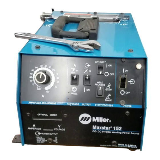
- Page 1 Maxstar 152 And 175 Visit our website at www.MillerWelds.com OM-206 October 1999 Processes TIG (GTAW) Welding Stick (SMAW) Welding Description Arc Welding Power Source 152 Model 175 Model 141 754F...
- Page 2 ISO 9001 Quality System Standard. service information for your particular model are also provided. Miller Electric manufactures a full line of welders and welding related equipment. For information on other quality Miller products, contact your local Miller distributor to receive the latest full line catalog or individual catalog sheets.
-
Page 3: Table Of Contents
3-5. Remote 14 Receptacle Information And Connections 3-6. Remote 14 Socket Information 3-7. Connecting Input Power To 152 Models 3-8. Electrical Service Guide For 152 Ampere Models 3-9. Connecting Input Power To 175 Models 3-10. Electrical Service Guide For 175 Ampere Models SECTION 4 –... -
Page 5: Section 1 - Safety Precautions - Read Before Using
SECTION 1 – SAFETY PRECAUTIONS - READ BEFORE USING 1-1. Symbol Usage Means Warning! Watch Out! There are possible hazards with this procedure! The possible hazards are shown in the adjoining symbols. Y Marks a special safety message. Means “Note”; not safety related. 1-2. - Page 6 ARC RAYS can burn eyes and skin. Arc rays from the welding process produce intense visible and invisible (ultraviolet and infrared) rays that can burn eyes and skin. Sparks fly off from the weld. D Wear a welding helmet fitted with a proper shade of filter to protect your face and eyes when welding or watching (see ANSI Z49.1 and Z87.1 listed in Safety Standards).
-
Page 7: Additional Symbols For Installation, Operation, And Maintenance
1-3. Additional Symbols For Installation, Operation, And Maintenance FIRE OR EXPLOSION hazard. D Do not install or place unit on, over, or near combustible surfaces. D Do not install unit near flammables. D Do not overload building wiring – be sure power supply system is properly sized, rated, and protected to handle this unit. -
Page 8: Emf Information
1-5. EMF Information Considerations About Welding And The Effects Of Low Frequency Electric And Magnetic Fields Welding current, as it flows through welding cables, will cause electro- magnetic fields. There has been and still is some concern about such fields. However, after examining more than 500 studies spanning 17 years of research, a special blue ribbon committee of the National Research Council concluded that: “The body of evidence, in the committee’... -
Page 9: Section 1 - Consignes De Securite - Lire Avant Utilisation
SECTION 1 – CONSIGNES DE SECURITE – LIRE AVANT 1-1. Signification des symboles Signifie Mise en garde ! Soyez vigilant ! Cette procédure présente des risques de danger ! Ceux-ci sont identifiés par des symboles adjacents aux directives. Y Identifie un message de sécurité particulier. Signifie NOTA ;... - Page 10 LES RAYONS DE L’ARC peuvent pro- voquer des brûlures dans les yeux et sur la peau. Le rayonnement de l’arc du procédé de soudage génère des rayons visibles et invisibles intenses (ultraviolets et infrarouges) susceptibles de provoquer des brûlures dans les yeux et sur la peau. Des étincelles sont projetées pendant le soudage.
-
Page 11: Dangers Supplémentaires En Relation Avec L'installation, Le Fonctionnement Et La Maintenance
1-3. Dangers supplémentaires en relation avec l’installation, le fonctionnement et la maintenance Risque D’INCENDIE OU D’EXPLOSION. D Ne pas placer l’appareil sur, au-dessus ou à proxi- mité de surfaces infllammables. D Ne pas installer l’appareil à proximité de produits inflammables D Ne pas surcharger l’installation électrique –... -
Page 12: Principales Normes De Sécurité
1-4. Principales normes de sécurité Safety in Welding and Cutting, norme ANSI Z49.1, de l’American Wel- ding Society, 550 N.W. Lejeune Rd, Miami FL 33126 Safety and Health Sandards, OSHA 29 CFR 1910, du Superintendent of Documents, U.S. Government Printing Office, Washington, D.C. 20402. -
Page 13: Section 2 - Specifications
1–150 100% Duty Cycle 140 A @ 25.6 Volts DC, 1–175 100% Duty Cycle * While idling 2-2. Volt-Ampere Curves A. 152 Model Maximum Amperes Input at Open-Circuit Rated Load Output Voltage DC 230 Volts AC; 50/60 Hz; Single-Phase 27.1 (0.5)* 460 Volts AC;... -
Page 14: Duty Cycle And Overheating
2-3. Duty Cycle And Overheating 100% Duty Cycle At 120 Amperes For 152 Models; 140 Amperes For 175 Models A. 152 Model Overheating When overheated, thermostat opens, output stops, and cooling fan keeps running. OM-206 Page 10 Continuous Welding minutes Let fan run for 15 minutes. -
Page 15: Section 3 - Installation
SECTION 3 – INSTALLATION 3-1. Selecting A Location Rear Right 3-2. Selecting And Preparing Weld Output Cables Tools Needed: 3-3. Weld Cable Size* 100 ft (30 m) Or Less Welding 10 To 60% 60 Thru 100% Amperes Duty Cycle Duty Cycle *Weld cable size (AWG) is based on either a 4 volts or less drop or a current density of at least than 300 circular mils per ampere. -
Page 16: Connecting To Weld Output Receptacles
(+) receptacle. For Electrode Negative (DCEN), reverse cable connections. Align keyway, insert connector, and turn clockwise. Ref. SC-140 373 / Ref. ST-152 126 Remote 14 Receptacle RC7 (See Section 3-6) Keyway Plug Threaded Collar... -
Page 17: Remote 14 Socket Information
AMPERAGE/ VOLTAGE *The remaining sockets are not used. 3-7. Connecting Input Power To 152 Models 3-8. Electrical Service Guide For 152 Ampere Models Input Voltage Input Amperes At Rated Output Max Recommended Standard Fuse Or Circuit Breaker Rating In Amperes... -
Page 18: Connecting Input Power To 175 Models
3-9. Connecting Input Power To 175 Models Tools Needed: 3-10. Electrical Service Guide For 175 Ampere Models Input Voltage Input Amperes At Rated Output Max Recommended Standard Fuse Or Circuit Breaker Rating In Amperes Min Input Conductor Size In AWG/Kcmil Max Recommended Input Conductor Length In Feet (Meters) Min Grounding Conductor Size In AWG/Kcmil Reference: 1993 National Electrical Code (NEC). -
Page 19: Section 4 - Operation
Amperage Control Switch Output (Contactor) Switch Lift-Arc Switch Weld Process Switch Power Switch Pilot Light ST-152 127-A Output (Contactor) Switch Use switch to select way of control- ling output. For front panel control, place switch in On position. For remote control, place switch in Remote 14 position (see Section 3-5). -
Page 20: Amperage Controls
4-3. Amperage Controls EXAMPLE Of Combination Remote Amperage Control Set Switches 4-4. Weld Process Switch OM-206 Page 16 Use control to select weld amper- age. Amperage may be adjusted while welding. Use switch to select way of control- ling amperage adjustment. For front panel control, place switch in Panel position. -
Page 21: Lift-Arc Switch
NOTE Lift-Arc switch must be in Off position when using a High-Frequency unit with this welding power source, or when using the SMAW welding process. 4-5. Lift-Arc Switch 4-6. Power Switch And Pilot Light 1 – 2 “Touch” Seconds Do NOT Strike Like A Match! Lift-Arc Switch Use switch to select Lift-Arc On or Off. -
Page 22: Section 5 - Maintenance & Troubleshooting
SECTION 5 – MAINTENANCE & TROUBLESHOOTING 5-1. Routine Maintenance 3 Months Replace Unreadable Labels Section Tape Or Replace Cracked Cables Replace Cracked Parts 14-Pin Cord – – Hose Torch Cable OM-206 Page 18 Turn Off all power before maintaining. 3 Months Clean Tighten Weld Connections... -
Page 23: Measuring Input Capacitor Voltage
5-2. Measuring Input Capacitor Voltage Significant DC voltage can remain on capacitors after unit is Off. Always check capacitors as shown to be sure they have discharged before working on unit. Tools Needed: 5/16 in Turn Off welding power source and disconnect input power. -
Page 24: Troubleshooting
Be sure Power switch is On (see Section 4-6). erative. Secure power cord plug in receptacle (152 model) (see Section 3-7). Be sure line disconnect switch is On (see Section 3-9). Check line fuse(s) and replace if necessary. Reset circuit breakers (see Sections 3-7 or 3-9). - Page 25 Notes OM-206 Page 21...
-
Page 26: Section 6 - Electrical Diagrams
SECTION 6 – ELECTRICAL DIAGRAMS SC-166 403 Figure 6-1. Circuit Diagram For 152 Model OM-206 Page 22... - Page 27 SC-170 697 Figure 6-2. Circuit Diagram For 175 Model OM-206 Page 23...
-
Page 28: Section 7 - Selecting And Preparing Tungsten Electrode
SECTION 7 – SELECTING AND PREPARING TUNGSTEN ELECTRODE NOTE For additional information, see your distributor for a handbook on the Gas Tungsten Arc Welding (GTAW) process.Wear clean gloves to prevent contamination of tungsten electrode. 7-1. Selecting Tungsten Electrode Electrode Diameter DC –... -
Page 29: Preparing Tungsten For Ac Or Dc Electrode Positive (Dcep) Welding
7-2. Preparing Tungsten For AC Or DC Electrode Positive (DCEP) Welding 7-3. Preparing Tungsten For DC Electrode Negative (DCEN) Welding Ideal Tungsten Preparation – Stable Arc Wrong Tungsten Preparation – Wandering Arc 1-1/2 Times Electrode Diameter 2-1/2 Times Electrode Diameter Tungsten Electrode Balled End Y Understand... -
Page 30: Section 8 - Guidelines For Tig Welding (Gtaw)
SECTION 8 – GUIDELINES FOR TIG WELDING (GTAW) 8-1. Positioining The Torch 10–15 8-2. Torch Movement During Welding Tungsten Without Filler Rod Welding direction Form pool Tungsten With Filler Rod Welding direction Form pool OM-206 Page 26 10–25 Tilt torch Tilt torch Remove rod of pool. -
Page 31: Positioning Torch Tungsten For Various Weld Joints
8-3. Positioning Torch Tungsten For Various Weld Joints Butt Weld And Stringer Bead “T” Joint Lap Joint Corner Joint ST-162 003 / S-0792 OM-206 Page 27... -
Page 32: Section 9 - Parts List
SECTION 9 – PARTS LIST Figure 9-1. Main Assembly (175 Model Illustrated) OM-206 Page 28 Hardware is common and not available unless listed. *18 Is Supplied with 152 Model only ST-145 668-J... - Page 33 Item Dia. Part Mkgs....195 585 ....134 327 .
- Page 34 Item Dia. Part Mkgs... . PLG11 ..115 094 ..... . 113 746 .
- Page 35 ..LABEL, warning exploding parts etc VARISTOR, 40 joule 390VDC *14 Is Supplied with 152 Model only Quantity Model ....
- Page 36 Item Dia. Part Mkgs....030 839 ....151 479 ..
- Page 37 Notes...
- Page 39 Warranty Questions? Call LIMITED WARRANTY – Subject to the terms and conditions below, Miller Electric Mfg. Co., Appleton, Wisconsin, warrants 1-800-4-A-MILLER to its original retail purchaser that new Miller equipment sold for your local after the effective date of this limited warranty is free of defects in material and workmanship at the time it is shipped by Miller.
- Page 40 Parts) Circuit Diagrams Welding Process Handbooks File a claim for loss or damage during shipment. 2000 Miller Electric Mfg. Co. 6/00 Miller Electric Mfg. Co. An Illinois Tool Works Company 1635 West Spencer Street Appleton, WI 54914 USA International Headquarters–USA USA Phone: 920-735-4505 Auto-Attended USA &...