
Related Manuals for Miller Electric Spoolmate 100 Series


Summary of Contents for Miller Electric Spoolmate 100 Series
- Page 1 OM-234 016F 2010−04 Processes MIG (GMAW) Welding Description Wire Feeder Spool Gun Spoolmate 100 Series File: Wire Feeder Visit our website at www.MillerWelds.com...
- Page 2 ISO 9001 Quality System Standard. particular model are also provided. Miller Electric manufactures a full line of welders and welding related equipment. For information on other quality Miller products, contact your local Miller distributor to receive the latest full line catalog or individual specification sheets.
-
Page 3: Table Of Contents
TABLE OF CONTENTS SECTION 1 − SAFETY PRECAUTIONS - READ BEFORE USING ....... . . 1-1. -
Page 5: Section 1 − Safety Precautions - Read Before Using
SECTION 1 − SAFETY PRECAUTIONS - READ BEFORE USING som _2010−03 Protect yourself and others from injury — read and follow these precautions. 1-1. Symbol Usage DANGER! − Indicates a hazardous situation which, if Indicates special instructions. not avoided, will result in death or serious injury. The possible hazards are shown in the adjoining symbols or explained in the text. - Page 6 D Remove stick electrode from holder or cut off welding wire at FUMES AND GASES can be hazardous. contact tip when not in use. D Wear oil-free protective garments such as leather gloves, heavy Welding produces fumes and gases. Breathing shirt, cuffless trousers, high shoes, and a cap.
-
Page 7: Additional Symbols For Installation, Operation, And Maintenance
1-3. Additional Symbols For Installation, Operation, And Maintenance FIRE OR EXPLOSION hazard. MOVING PARTS can injure. D Do not install or place unit on, over, or near D Keep away from moving parts such as fans. combustible surfaces. D Keep all doors, panels, covers, and guards D Do not install unit near flammables. -
Page 8: California Proposition 65 Warnings
1-4. California Proposition 65 Warnings For Gasoline Engines: Welding or cutting equipment produces fumes or gases which contain chemicals known to the State of California to Engine exhaust contains chemicals known to the State of cause birth defects and, in some cases, cancer. (California California to cause cancer, birth defects, or other reproduc- Health &... -
Page 9: Section 2 − Consignes De Sécurité − Lire Avant Utilisation
SECTION 2 − CONSIGNES DE SÉCURITÉ − LIRE AVANT UTILISATION fre_som_2010−03 Se protéger et protéger les autres contre le risque de blessure — lire et respecter ces consignes. 2-1. Symboles utilisés DANGER! − Indique une situation dangereuse qui si on Indique des instructions spécifiques. - Page 10 Il reste une TENSION DC NON NÉGLIGEABLE dans LE SOUDAGE peut provoquer un les sources de soudage onduleur UNE FOIS incendie ou une explosion. l’alimentation coupée. Le soudage effectué sur des conteneurs fermés tels D Arrêter les convertisseurs, débrancher le courant électrique et que des réservoirs, tambours ou des conduites peut décharger les condensateurs d’alimentation selon les instructions provoquer leur éclatement.
-
Page 11: Dangers Supplémentaires En Relation Avec L'installation, Le Fonctionnement Et La Maintenance
ACCUMULATIONS LES BOUTEILLES peuvent exploser risquent de provoquer des blessures si elles sont endommagées. ou même la mort. Des bouteilles de gaz protecteur contiennent du gaz sous haute pression. Si une bouteille est endom- D Fermer l’alimentation du gaz protecteur en cas magée, elle peut exploser. -
Page 12: Proposition Californienne 65 Avertissements
Les PIÈCES MOBILES peuvent RAYONNEMENT HAUTE causer des blessures. FRÉQUENCE (H.F.) risque provoquer des interférences. D Ne pas s’approcher des organes mobiles. D Ne pas s’approcher des points de coincement D Le rayonnement haute fréquence (H.F.) peut tels que des rouleaux de commande. provoquer des interférences avec les équi- pements de radio−navigation et de com- munication, les services de sécurité... -
Page 13: Principales Normes De Sécurité
2-5. Principales normes de sécurité Safety in Welding, Cutting, and Allied Processes, ANSI Standard Z49.1, 25 West 43rd Street, New York, NY 10036 (téléphone : 212-642-4900, de Global Engineering Documents (téléphone : 1-877-413-5184, site site Internet : www.ansi.org). Internet : www.global.ihs.com). Standard for Fire Prevention During Welding, Cutting, and Other Hot Safe Practices for the Preparation of Containers and Piping for Welding Work, NFPA Standard 51B, de National Fire Protection Association,... - Page 14 OM-234 016 Page 10...
-
Page 15: Section 3 − Installation
SECTION 3 − INSTALLATION 3-1. Specifications Approximate Wire Cooling Maximum Weld Circuit Wire Diameter Range Overall Dimensions Weight Feed Range Method Spool Size Rating Millermatic 140 AutoSet: 5 To 365 ipm .030 Thru .035 in. Length: (0.8 Thru 0.9 mm) (0.13 To 9.27 mpm) 13 in. -
Page 16: Connecting Spool Gun To Millermatic 140/180 Models
3-3. Connecting Spool Gun To Millermatic 140/180 Models A. Installing Optional Spool Gun Switch In Millermatic 140/180 Models Renegade Passport Plus Models: Discard switch assembly; unit pre−wired for spool gun option. Go to Section 3-5 or 3-6. Turn Off unit, and disconnect input power. - Page 17 B. Connecting Spool Gun To Millermatic 140/180 Drive Assembly Spool Gun Gun Securing Knob Gun End Loosen thumbscrew. Insert end through opening until it bottoms against drive assembly. Tighten gun securing knob. Spool gun must be inserted completely to prevent leakage of shielding gas.
-
Page 18: Connecting Spool Gun To Millermatic 211 Auto-Sett
3-4. Connecting Spool Gun To Millermatic 211 Auto-Sett Drive Assembly Spool Gun Gun Securing Knob Gun End Loosen thumbscrew. Insert end through opening until it bottoms against drive assembly. Tighten gun securing knob. Spool gun must be inserted completely to prevent leakage of shielding gas. -
Page 19: Connecting Spool Gun To Millermatic Passport Plus
3-5. Connecting Spool Gun To Millermatic Passport Plus Drive Assembly Spool Gun Gun Securing Knob Gun End Loosen thumbscrew. Insert end through opening until it bottoms against drive assembly. Tighten gun securing knob. Spool gun must be inserted completely to prevent leakage of shielding gas. -
Page 20: Connecting Spool Gun To Renegade 180
3-6. Connecting Spool Gun To Renegade 180 Drive Assembly Spool Gun Gun Securing Knob Gun End Loosen gun securing knob. Insert end through opening until it bottoms against drive assembly. Tighten gun securing knob. Be sure that gun end is tight against drive assembly. -
Page 21: Installing Wire Spool And Threading Welding Wire
3-7. Installing Wire Spool And Threading Welding Wire Thumb Screw Spool Cover Remove thumb screw and spool Tools Needed: cover. Hub Tension Nut Wire Spool Install spool so wire feeds from top. Turn hub tension nut just so a slight drag is felt on the wire spool. -
Page 22: Section 4 − Operation
SECTION 4 − OPERATION 4-1. Controls For Millermatic 140/180 Models A. Spool Gun Operation On Millermatic 140/180 Models Spool Gun/MIG Gun switch on Millermatic 140/180 must be in Spool Gun position for spool gun to operate. Shielding Gas Cylinder For shielding gas connections, see welding power source Owner’s Manual. - Page 23 Notes OM-234 016 Page 19...
- Page 24 B. Weld Parameter Chart For Millermatic 140 Model w/Auto−SetE Auto−Sett − SIMPLE SETUP FOR WELDING MILD STEEL Example: .030” diameter wire, welding 18 ga. material. Activate Auto−Sett by selecting the diameter of the welding wire .024” Auto−Set* with the WIRE SPEED knob. WELD WIRE .030”...
- Page 25 Manual Setup Refer to chart below to select Voltage and Wire Speed based on thickness of metal being welded. 1. Number on right of slash is Wire Speed Knob Setting. (Example: 4 / 65) M A TER I A L T H I 2.
- Page 26 C. Weld Parameter Chart For Millermatic 140 Model w/Factory Set Non-Wire Speed Tracking Mode Refer to chart below to select Voltage and Wire Speed based on thickness of material being welded. 1. Number on left of 2. Number on right slash is Voltage of slash is Wire Knob Setting.
- Page 27 NOTE: Settings are approximate. Adjust as required. “---” Means not recommended. “*” Thicker materials can be welded using proper technique, joint preparation and multiple passes. IMPORTANT: Match drive roll groove to diameter of wire being used. Set Tension knob setting to 3 at start. Adjust tension per instructions in the manual.
- Page 28 D. Weld Parameter Chart For Millermatic 180 Model w/Factory Set Non-Wire Speed Tracking Mode Refer to chart below to select Voltage and Wire Speed based on thickness of material being welded. 1. Number on left of 2. Number on right slash is Voltage of slash is Wire Knob Setting.
- Page 29 NOTE: Settings are approximate. Adjust as required. “−−−” Means not recommended. Thicker materials can be welded using proper technique, joint preparation and multiple passes. IMPORTANT: Match drive roll groove to diameter of wire being used. Set Tension knob setting to 3 at start. Adjust tension per instructions in the manual. 1.5/20 2/25 2/25...
-
Page 30: Controls For Millermatic 211 Auto-Sett Models
4-2. Controls For Millermatic 211 Auto-Sett Models A. Spool Gun Operation On Millermatic 211 Auto-Sett Models Spool Gun/MIG Gun switch on Millermatic 211 Auto-Sett must be in Spool Gun position for spool gun to operate. Shielding Gas Cylinder For shielding gas connections, see welding power source Owner’s Manual. - Page 31 Notes OM-234 016 Page 27...
- Page 32 B. Weld Parameter Chart For Millermatic 211 Auto−SetE Model Color parameter charts can be downloaded from www. MillerWelds.com or by ordering from a Miller distributor. OM-234 016 Page 28...
- Page 33 239 992-B OM-234 016 Page 29...
-
Page 34: Controls For Millermatic Passport Plus Model
4-3. Controls For Millermatic Passport Plus Model A. Spool Gun Operation On Millermatic Passport Plus Model Shielding Gas Cylinder For shielding gas connections, see welding power source Owner’s Manual. Valve Open valve on cylinder just before welding. Close valve on cylinder when finished welding. - Page 35 Notes OM-234 016 Page 31...
- Page 36 B. Weld Parameter Chart For Millermatic Passport Plus Model Refer to chart below to select Voltage and Wire Speed based on thickness of material being welded. 1. Number on left of 2. Number on right slash is Voltage of slash is Wire Knob Setting.
- Page 37 NOTE: Settings are approximate. Adjust as required. “---” Means not recommended. Thicker materials can be welded using proper technique, joint preparation and multiple passes. IMPORTANT: Match drive roll groove to diameter of wire being used. Set Tension knob setting to 3 at start. Adjust tension per instructions in the manual.
-
Page 38: Controls For Renegade 180 Model
4-4. Controls For Renegade 180 Model A. Spool Gun Operation On Renegade 180 Model Spool Gun/MIG Gun switch on Renegade 180 must be in Spool Gun position for spool gun to operate. Shielding Gas Cylinder For shielding gas connections, see welding power source Owner’s Manual. - Page 39 B. Weld Parameters For Renegade 180 Model Material Thickness Select Wire Type, Polarity, and Shielding Wire Size 20 ga 18 ga 16 ga 14 ga 1/8 in. 3/16 in. 1/4 in. 5/16 in. Shop Settings (Wall or Premise Power, 230 V 1 Ph) Aluminum 4043 (DCEP) 0.030 2.0/70...
-
Page 40: Section 5 − Maintenance & Troubleshooting
SECTION 5 − MAINTENANCE & TROUBLESHOOTING 5-1. Routine Maintenance Maintain more often Disconnect power during severe conditions. before maintaining. n = Check Z = Change ~ = Clean l = Replace Reference * To be done by Factory Authorized Service Agent l Unreadable Labels ~ Weld Terminals l Damaged Gas Hose... -
Page 41: Changing Drive Rolls
5-2. Changing Drive Rolls Turn Off power at welding power source first. Drive Roll Cover Remove cover. Changing Push Roll: To remove push roll: Push Roll Screw Washer Push Roll Remove screw and washer, and lift out drive roll. To install drive roll: Slide drive roll onto shaft and se- cure with washer and screw. -
Page 42: Changing Liner
5-3. Changing Liner Turn Off power at welding power source first. Nozzle Contact Tip Liner Remove and replace liner. Reinstall parts as shown. Tools Needed: Ref. 804 985-A 5-4. Troubleshooting Trouble Remedy No weld output; gun/feeder does not Place Power switch on welding power source in the On position (see welding power source Owner’s work. -
Page 43: Gmaw (Mig) Aluminum Welding Hints
5-5. GMAW (MIG) Aluminum Welding Hints Here are several hints to help you be more successful with your new aluminum feed system. MIG welding aluminum requires different techniques than MIG welding mild steel. A. Before You Start Welding The removal of lubricants from the aluminum base material may be necessary. Consult with your local welding distributor for their recommendation on aluminum cleaners. - Page 44 Maintain a 3/4 in. (19 mm) tip-to-work distance, and have the contact tip recessed approximately 1/8 in. inside the nozzle if possible. See Figure 5-2. Gas Nozzle Ç Ç Ç Ç Ç Ç Ç Ç Contact Tip To Work Ç Ç Ç Ç Contact Tube Recessed 1/8 Distance 3/4 in.
-
Page 45: Section 6 − Electrical Diagrams
SECTION 6 − ELECTRICAL DIAGRAMS 186 451 Figure 6-1. Circuit Diagram For Spoolmate OM-234 016 Page 41... - Page 46 Figure 6-2. Circuit Diagram For Millermatic 140/180 OM-234 016 Page 42...
- Page 47 234 419-B OM-234 016 Page 43...
-
Page 48: Section 7 − Parts List
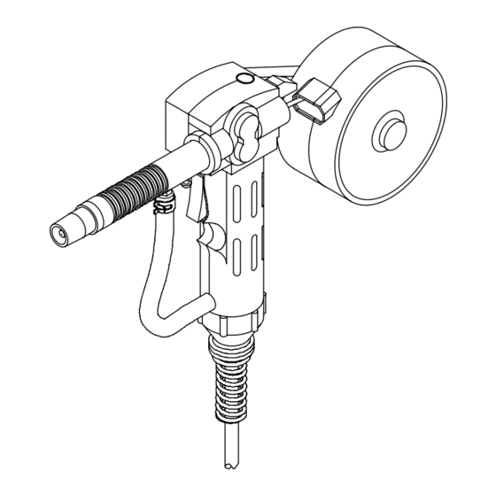
SECTION 7 − PARTS LIST Hardware is common and not available unless listed. 804 988-A Figure 7-1. Complete Assembly OM-234 016 Page 44... - Page 49 Item Dia. Part Quantity Mkgs. Description Figure 7-1. Complete Assembly ... 186 416 TRIGGER SWITCH ..........
- Page 50 Notes...
- Page 51 LIMITED WARRANTY − Subject to the terms and conditions 90 Days — Parts Call below, Miller Electric Mfg. Co., Appleton, Wisconsin, warrants to its Accessory (Kits) 1-800-4-A-MILLER original retail purchaser that new Miller equipment sold after the...
- Page 52 Contact the Delivering Carrier to: File a claim for loss or damage during shipment. For assistance in filing or settling claims, contact your distributor and/or equipment manufacturer’s Transportation Department. ORIGINAL INSTRUCTIONS − PRINTED IN USA 2010 Miller Electric Mfg. Co. 2010−01...