Asus Motherboard P5SD2-X User Manual
Asus p5sd2-x motherboard user manual
Hide thumbs
Also See for Motherboard P5SD2-X:
- Manual de démarrage rapide (20 pages) ,
- Installation manual (108 pages) ,
- Installation manual (90 pages)
Table of Contents
Advertisement
Quick Links
Advertisement
Table of Contents

Related Manuals for Asus Motherboard P5SD2-X


Summary of Contents for Asus Motherboard P5SD2-X
- Page 1 P5SD2-X...
- Page 2 Product warranty or service will not be extended if: (1) the product is repaired, modified or altered, unless such repair, modification of alteration is authorized in writing by ASUS; or (2) the serial number of the product is defaced or missing.
-
Page 3: Table Of Contents
Welcome! ... 1-2 Package contents ... 1-2 Special features ... 1-2 1.3.1 Product highlights ... 1-2 1.3.2 Innovative ASUS features ... 1-4 Before you proceed ... 1-5 Motherboard overview ... 1-6 1.5.1 Placement direction ... 1-6 1.5.2 Screw holes ... 1-6 1.5.3... - Page 4 Creating a bootable floppy disk ... 2-2 2.1.2 ASUS EZ Flash utility ... 2-3 2.1.3 AFUDOS utility ... 2-4 2.1.4 ASUS CrashFree BIOS 2 utility ... 2-6 2.1.5 ASUS Update utility ... 2-8 BIOS setup program ... 2-11 2.2.3 Navigation keys ... 2-12 2.2.1...
- Page 5 Support CD information ... 3-2 3.2.1 Running the support CD ... 3-2 3.2.2 Drivers menu ... 3-3 3.2.3 Utilities menu ... 3-4 3.2.4 Make Disk menu ... 3-5 3.2.5 Manuals menu ... 3-6 3.2.6 ASUS Contact information ... 3-6 v v v v v...
-
Page 6: Notices
Notices Federal Communications Commission Statement Federal Communications Commission Statement Federal Communications Commission Statement Federal Communications Commission Statement Federal Communications Commission Statement This device complies with Part 15 of the FCC Rules. Operation is subject to the following two conditions: • This device may not cause harmful interference, and •... -
Page 7: Safety Information
Safety information Electrical safety Electrical safety Electrical safety Electrical safety Electrical safety • To prevent electrical shock hazard, disconnect the power cable from the electrical outlet before relocating the system. • When adding or removing devices to or from the system, ensure that the power cables for the devices are unplugged before the signal cables are connected. -
Page 8: About This Guide
A S U S w e b s i t e s A S U S w e b s i t e s The ASUS website provides updated information on ASUS hardware and software products. Refer to the ASUS contact information. -
Page 9: Typography
Conventions used in this guide Conventions used in this guide Conventions used in this guide Conventions used in this guide Conventions used in this guide To make sure that you perform certain tasks properly, take note of the following symbols used throughout this manual. D A N G E R / W A R N I N G : D A N G E R / W A R N I N G : D A N G E R / W A R N I N G :... -
Page 10: P5Sd2-X Specifications Summary
AI Overclocking CPU LockFree ASUS Q-Fan ASUS CrashFree BIOS 2 ASUS MyLogo™ ASUS EZ Flash ASUS C.P.R. (CPU Parameter Recall) 4 MB Flash ROM, AMI BIOS, PnP, DMI2.0, SM BIOS 2.3, WfM2.0 (continued on the next page) ® 4/Pentium ®... - Page 11 ASUS PC Probe II ASUS Screen Saver Adobe Acrobat Reader Microsoft DirectX...
- Page 12 x i i x i i x i i x i i x i i...
-
Page 13: Chapter 1: Product Introduction
This chapter describes the motherboard features and the new technologies it supports. A S U S P 5 S D 2 - X A S U S P 5 S D 2 - X A S U S P 5 S D 2 - X A S U S P 5 S D 2 - X A S U S P 5 S D 2 - X Product... -
Page 14: Welcome
T h a n k y o u f o r b u y i n g a n A S U S The motherboard delivers a host of new features and latest technologies, making it another standout in the long line of ASUS quality motherboards! Before you start installing the motherboard, and hardware devices on it, check the items in your package with the list below. - Page 15 Intel Intel ® ® ® ® ® EM64T EM64T Intel Intel Intel EM64T EM64T EM64T The motherboard supports Intel (Extended Memory 64 Technology). The Intel computer to run on 64-bit operating systems and access larger amounts of system memory for faster and more efficient computing. See the Appendix for details.
-
Page 16: Innovative Asus Features
ASUS Q-Fan technology ASUS Q-Fan technology ASUS Q-Fan technology The ASUS Q-Fan technology smartly adjusts the CPU fan speed according to the system loading to ensure quiet, cool, and efficient operation. See pages 2-29 and 2-30 for details. ASUS MyLogo™... -
Page 17: Before You Proceed
Before you proceed Take note of the following precautions before you install motherboard components or change any motherboard settings. • Unplug the power cord from the wall socket before touching any component. • Use a grounded wrist strap or touch a safely grounded object or to a metal object, such as the power supply case, before handling components to avoid damaging them due to static electricity •... -
Page 18: Motherboard Overview
Motherboard overview Before you install the motherboard, study the configuration of your chassis to ensure that the motherboard fits into it. Make sure to unplug the power cord before installing or removing the motherboard. Failure to do so can cause you physical injury and damage motherboard components. -
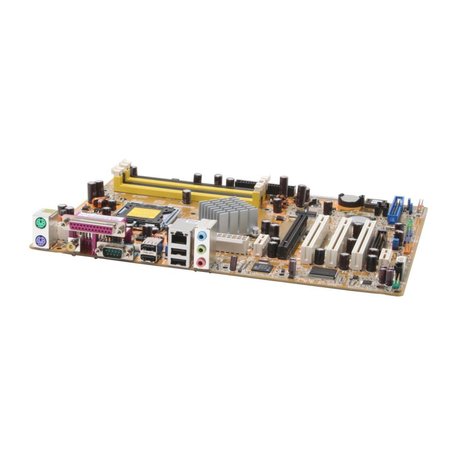
Page 19: Motherboard Layout
1.5.3 1.5.3 1.5.3 Motherboard layout Motherboard layout Motherboard layout 1.5.3 1.5.3 Motherboard layout Motherboard layout PS/2KBMS T: Mouse B: Keyboard SPDIF_O COM1 USB12 USBPW12 USBPW34 LAN_USB34 Top:Line In Center:Line Out Below:Mic In CPU_FAN CHA_FAN PCIEX1_1 Intel RC82540EM FLOPPY AD1986A PCIEX1_2 FP_AUDIO A S U S P 5 S D 2 - X A S U S P 5 S D 2 - X... -
Page 20: Central Processing Unit (Cpu)
Contact your retailer immediately if the PnP cap is missing, or if you see any damage to the PnP cap/socket pins/motherboard components. ASUS will shoulder the cost of repair only if the damage is shipment/ transit-related. •... - Page 21 Press the load lever with your thumb (A) and move it to the left (B) until it is released from the retention tab. R e t e n t i o n t a b R e t e n t i o n t a b R e t e n t i o n t a b R e t e n t i o n t a b R e t e n t i o n t a b...
- Page 22 The CPU fits in only one correct orientation. DO NOT force the CPU into the socket to prevent bending the connectors on the socket and damaging the CPU! Close the load plate (A), then push the load lever (B) until it snaps into the retention tab.
-
Page 23: Installling The Cpu Heatsink And Fan
2.3.2 2.3.2 2.3.2 Installling the CPU heatsink and fan Installling the CPU heatsink and fan Installling the CPU heatsink and fan 2.3.2 2.3.2 Installling the CPU heatsink and fan Installling the CPU heatsink and fan The Intel ® Pentium ® 4 LGA775 processor requires a specially designed heatsink and fan assembly to ensure optimum thermal condition and performance. - Page 24 Push down two fasteners at a time in a diagonal sequence to secure the heatsink and fan assembly in place. When the fan and heatsink assembly is in place, connect the CPU fan cable to the connector on the motherboard labeled CPU_FAN. ®...
-
Page 25: Uninstalling The Cpu Heatsink And Fan
2.3.3 2.3.3 Uninstalling the CPU heatsink and fan Uninstalling the CPU heatsink and fan 2.3.3 2.3.3 2.3.3 Uninstalling the CPU heatsink and fan Uninstalling the CPU heatsink and fan Uninstalling the CPU heatsink and fan To uninstall the CPU heatsink and fan: Disconnect the CPU fan cable from the connector on the motherboard labeled... - Page 26 Remove the heatsink and fan assembly from the motherboard. Rotate each fastener clockwise to reset the orientation. When reset, each fastener should be oriented as shown, with the narrow groove directed outward. 1 - 1 4 1 - 1 4 1 - 1 4 1 - 1 4 1 - 1 4...
-
Page 27: System Memory
• Use only qualified DIMMs modules on this motherboard. Visit the ASUS website (www.asus.com) for the latest DDR2 Qualified Vendors List (QVL). A S U S P 5 S D 2 - X A S U S P 5 S D 2 - X... - Page 28 Table 1 Recommended memory configurations Table 1 Recommended memory configurations Table 1 Recommended memory configurations Table 1 Recommended memory configurations Table 1 Recommended memory configurations For dual-channel configuration, the total size of memory module(s) installed per channel must be the same to ensure optimum performance.
-
Page 29: Installing A Dimm
1.7.3 1.7.3 Installing a DIMM Installing a DIMM 1.7.3 1.7.3 1.7.3 Installing a DIMM Installing a DIMM Installing a DIMM Unplug the power supply before adding or removing DIMMs or other system components. Failure to do so can cause severe damage to both the motherboard and the components. -
Page 30: Expansion Slots
Expansion slots In the future, you may need to install expansion cards. The following sub-sections describe the slots and the expansion cards that they support. Make sure to unplug the power cord before adding or removing expansion cards. Failure to do so may cause you physical injury and damage motherboard components. -
Page 31: Interrupt Assignments
1.8.3 1.8.3 1.8.3 Interrupt assignments Interrupt assignments Interrupt assignments 1.8.3 1.8.3 Interrupt assignments Interrupt assignments Standard interrupt assignments Standard interrupt assignments Standard interrupt assignments Standard interrupt assignments Standard interrupt assignments I R Q I R Q I R Q I R Q I R Q P r i o r i t y P r i o r i t y... -
Page 32: Pci Slots
1.8.4 1.8.4 PCI slots PCI slots 1.8.4 1.8.4 1.8.4 PCI slots PCI slots PCI slots The PCI slots support cards such as a LAN card, SCSI card, USB card, and other cards that comply with PCI specifications. The figure shows a LAN card installed on a PCI slot. -
Page 33: Jumpers
Jumpers 1 . 1 . C l e a r R T C R A M ( C L R T C ) C l e a r R T C R A M ( C L R T C ) C l e a r R T C R A M ( C L R T C ) C l e a r R T C R A M ( C L R T C ) C l e a r R T C R A M ( C L R T C ) - Page 34 2 . 2 . U S B d e v i c e w a k e - u p ( 3 - p i n U S B P W 1 2 , U S B P W 3 4 , U S B d e v i c e w a k e - u p ( 3 - p i n U S B P W 1 2 , U S B P W 3 4 , U S B d e v i c e w a k e - u p ( 3 - p i n U S B P W 1 2 , U S B P W 3 4 , U S B d e v i c e w a k e - u p ( 3 - p i n U S B P W 1 2 , U S B P W 3 4 ,...
-
Page 35: 1.10 Connectors
1.10 Connectors 1.10.1 1.10.1 Rear panel connectors 1.10.1 Rear panel connectors Rear panel connectors Rear panel connectors 1.10.1 1.10.1 Rear panel connectors 1 . 1 . P S / 2 m o u s e p o r t ( g r e e n ) . P S / 2 m o u s e p o r t ( g r e e n ) . -
Page 36: Internal Connectors
7 . 7 . U S B 2 . 0 p o r t s 3 a n d 4 . These two 4-pin Universal Serial Bus U S B 2 . 0 p o r t s 3 a n d 4 . U S B 2 . - Page 37 2 . 2 . I D E c o n n e c t o r s ( 4 0 - 1 p i n P R I _ I D E , S E C _ I D E ) I D E c o n n e c t o r s ( 4 0 - 1 p i n P R I _ I D E , S E C _ I D E ) I D E c o n n e c t o r s ( 4 0 - 1 p i n P R I _ I D E , S E C _ I D E ) I D E c o n n e c t o r s ( 4 0 - 1 p i n P R I _ I D E , S E C _ I D E )
-
Page 38: Hard Disk Drives
3 . 3 . S e r i a l A T A c o n n e c t o r s S e r i a l A T A c o n n e c t o r s S e r i a l A T A c o n n e c t o r s S e r i a l A T A c o n n e c t o r s S e r i a l A T A c o n n e c t o r s... - Page 39 5 . 5 . U S B c o n n e c t o r s ( 1 0 - 1 p i n U S B 5 6 , U S B 7 8 ) U S B c o n n e c t o r s ( 1 0 - 1 p i n U S B 5 6 , U S B 7 8 ) U S B c o n n e c t o r s ( 1 0 - 1 p i n U S B 5 6 , U S B 7 8 ) U S B c o n n e c t o r s ( 1 0 - 1 p i n U S B 5 6 , U S B 7 8 ) U S B c o n n e c t o r s ( 1 0 - 1 p i n U S B 5 6 , U S B 7 8 )
-
Page 40: Atx Power Connectors
7 . 7 . A T X p o w e r c o n n e c t o r s ( 2 4 - p i n E A T X P W R , A T X p o w e r c o n n e c t o r s ( 2 4 - p i n E A T X P W R , A T X p o w e r c o n n e c t o r s ( 2 4 - p i n E A T X P W R , A T X p o w e r c o n n e c t o r s ( 2 4 - p i n E A T X P W R , A T X p o w e r c o n n e c t o r s ( 2 4 - p i n E A T X P W R ,... - Page 41 8 . 8 . I n t e r n a l a u d i o c o n n e c t o r s ( 4 - p i n C D , A U X ) I n t e r n a l a u d i o c o n n e c t o r s ( 4 - p i n C D , A U X ) I n t e r n a l a u d i o c o n n e c t o r s ( 4 - p i n C D , A U X ) I n t e r n a l a u d i o c o n n e c t o r s ( 4 - p i n C D , A U X )
-
Page 42: System Panel Connector
1 0 . S y s t e m p a n e l c o n n e c t o r ( 2 0 - p i n P A N E L ) 1 0 . 1 0 . S y s t e m p a n e l c o n n e c t o r ( 2 0 - p i n P A N E L ) S y s t e m p a n e l c o n n e c t o r ( 2 0 - p i n P A N E L ) S y s t e m p a n e l c o n n e c t o r ( 2 0 - p i n P A N E L ) -
Page 43: Chapter 2: Bios Setup
This chapter tells how to change the system settings through the BIOS Setup menus. Detailed descriptions of the BIOS parameters are also provided. A S U S P 5 S D 2 - X A S U S P 5 S D 2 - X A S U S P 5 S D 2 - X A S U S P 5 S D 2 - X A S U S P 5 S D 2 - X... -
Page 44: Managing And Updating Your Bios
Refer to the corresponding sections for details on these utilities. Save a copy of the original motherboard BIOS file to a bootable floppy disk in case you need to restore the BIOS in the future. Copy the original motherboard BIOS using the ASUS Update or AFUDOS utilities. 2.1.1 2.1.1... -
Page 45: Asus Ez Flash Utility
ASUS EZ Flash utility ASUS EZ Flash utility The ASUS EZ Flash feature allows you to update the BIOS without having to go through the long process of booting from a floppy disk and using a DOS-based utility. The EZ Flash utility is built-in the BIOS chip so it is accessible by pressing <Alt>... -
Page 46: Afudos Utility
2.1.3 2.1.3 AFUDOS utility AFUDOS utility 2.1.3 2.1.3 2.1.3 AFUDOS utility AFUDOS utility AFUDOS utility The AFUDOS utility allows you to update the BIOS file in DOS environment using a bootable floppy disk with the updated BIOS file. This utility also allows you to copy the current BIOS file that you can use as backup when the BIOS fails or gets corrupted during the updating process. - Page 47 Updating the BIOS file To update the BIOS file using the AFUDOS utility: Visit the ASUS website (www.asus.com) and download the latest BIOS file for the motherboard. Save the BIOS file to a bootable floppy disk. Write the BIOS filename on a piece of paper. You need to type the exact BIOS filename at the DOS prompt.
-
Page 48: Asus Crashfree Bios 2 Utility
ASUS CrashFree BIOS 2 utility ASUS CrashFree BIOS 2 utility The ASUS CrashFree BIOS 2 is an auto recovery tool that allows you to restore the BIOS file when it fails or gets corrupted during the updating process. You can update a corrupted BIOS file using the motherboard support CD or the floppy disk that contains the updated BIOS file. - Page 49 Restart the system after the utility completes the updating process. The recovered BIOS may not be the latest BIOS version for this motherboard. Visit the ASUS website (www.asus.com) to download the latest BIOS file. A S U S P 5 S D 2 - X...
-
Page 50: Asus Update Utility
2.1.5 ASUS Update utility ASUS Update utility ASUS Update utility The ASUS Update is a utility that allows you to manage, save, and update the motherboard BIOS in Windows allows you to: • Save the current BIOS file • Download the latest BIOS file from the Internet •... - Page 51 Updating the BIOS through the Internet To update the BIOS through the Internet: Launch the ASUS Update utility from the Windows S t a r t > P r o g r a m s S t a r t...
- Page 52 S t a r t A S U S U p d a t e A S U S U p d a t e. The ASUS Update main window appears. A S U S U p d a t e...
-
Page 53: Bios Setup Program
• Visit the ASUS website (www.asus.com) to download the latest BIOS file for this motherboard. A S U S P 5 S D 2 - X A S U S P 5 S D 2 - X... -
Page 54: Navigation Keys
2.2.1 2.2.1 BIOS menu screen BIOS menu screen 2.2.1 2.2.1 2.2.1 BIOS menu screen BIOS menu screen BIOS menu screen M e n u i t e m s M e n u i t e m s M e n u i t e m s M e n u i t e m s M e n u i t e m s M e n u b a r... -
Page 55: Menu Items
Language [English] Use [+] or [-] to Primary IDE Master :[ST320413A] configure system time. Primary IDE Slave :[ASUS CD-S340] Secondary IDE Master :[Not Detected] Secondary IDE Slave :[Not Detected] Third IDE Master :[Not Detected] Fourth IDE Master... -
Page 56: Main Menu
Main menu When you enter the BIOS Setup program, the Main menu screen appears, giving you an overview of the basic system information. Refer to section “2.2.1 BIOS menu screen” for information on the menu screen items and how to navigate through them. System Time System Date Legacy Diskette A... - Page 57 2.3.4 2.3.4 Primary, Secondary IDE Master/Slave, Third Primary, Secondary IDE Master/Slave, Third 2.3.4 2.3.4 2.3.4 Primary, Secondary IDE Master/Slave, Third Primary, Secondary IDE Master/Slave, Third Primary, Secondary IDE Master/Slave, Third and Fourth IDE Master and Fourth IDE Master and Fourth IDE Master and Fourth IDE Master and Fourth IDE Master While entering Setup, the BIOS automatically detects the presence of IDE...
-
Page 58: Onboard Pci S-Ata Controller
PIO Mode [Auto] PIO Mode [Auto] PIO Mode [Auto] PIO Mode [Auto] PIO Mode [Auto] Selects the PIO mode. Configuration options: [Auto] [0] [1] [2] [3] [4] DMA Mode [Auto] DMA Mode [Auto] DMA Mode [Auto] DMA Mode [Auto] DMA Mode [Auto] Selects the DMA mode. -
Page 59: System Information
2.3.6 2.3.6 2.3.6 System Information System Information System Information 2.3.6 2.3.6 System Information System Information This menu gives you an overview of the general system specifications. The BIOS automatically detects the items in this menu. AMIBIOS Version : 0204 Build Date : 09/23/05 Processor Type : Genuine Intel(R) CPU 3.20GHz... -
Page 60: Advanced Menu
Advanced menu The Advanced menu items allow you to change the settings for the CPU and other system devices. Take caution when changing the settings of the Advanced menu items. Incorrect field values can cause the system to malfunction. JumperFree Configuration CPU Configuration Chipset Onboard Devices Configuration... - Page 61 The following item appears only when the AI Overclocking item is set to [Manual]. Auto Detect CPU Frequency [Enabled] Auto Detect CPU Frequency [Enabled] Auto Detect CPU Frequency [Enabled] Auto Detect CPU Frequency [Enabled] Auto Detect CPU Frequency [Enabled] Enables or disables the CPU frequency auto-detect feature. Configuration options: [Disabled] [Enabled] Auto Detect DRAM Frequency [Enabled] Auto Detect DRAM Frequency [Enabled]...
-
Page 62: Cpu Configuration
2.4.2 2.4.2 2.4.2 CPU Configuration CPU Configuration CPU Configuration 2.4.2 2.4.2 CPU Configuration CPU Configuration The items in this menu show the CPU-related information that the BIOS automatically detects. Configure Advanced CPU settings Manufacturer: Intel Brand String: Genuine Intel(R) CPU 2.80GHz Frequency : 3800 MHz FSB Speed... -
Page 63: Chipset
Adjacent Cache Line Prefetch [Enabled] Adjacent Cache Line Prefetch [Enabled] Adjacent Cache Line Prefetch [Enabled] Adjacent Cache Line Prefetch [Enabled] Adjacent Cache Line Prefetch [Enabled] Disables or enables the adjacent cache line prefetch feature. Configuration options: [Disabled] [Enabled] CPU Internal Thermal Control [Auto] CPU Internal Thermal Control [Auto] CPU Internal Thermal Control [Auto] CPU Internal Thermal Control [Auto]... - Page 64 NorthBridge SIS656 Configuration NorthBridge SIS656 Configuration NorthBridge SIS656 Configuration NorthBridge SIS656 Configuration NorthBridge SIS656 Configuration The items in this sub-menu show the SIS 656 NorthBridge related configuration. Primary Graphics Adapter CPU FSB Set To Chipset Timing DRAM CAS# Latency 128 Bit Access Mode Setting Primary Graphics Adapter [PCI ] Allows selection of the graphics controller to use as primary boot device.
-
Page 65: Onboard Devices Configuration
2.4.4 2.4.4 Onboard Devices Configuration Onboard Devices Configuration 2.4.4 2.4.4 2.4.4 Onboard Devices Configuration Onboard Devices Configuration Onboard Devices Configuration Configure Win627EHF Super IO Chipset Onboard LAN Onboard LAN Boot ROM Serial Port1 Address Parallel Port Address Parallel Port Mode ECP Mode DMA Channel Parallel Port IRQ Onboard Game/MIDI Port... -
Page 66: Pci Pnp
OnBoard Game/MIDI Port [Disabled] OnBoard Game/MIDI Port [Disabled] OnBoard Game/MIDI Port [Disabled] OnBoard Game/MIDI Port [Disabled] OnBoard Game/MIDI Port [Disabled] Disables or sets the OnBoard Game/MIDI port. Configuration options: [Disabled] [200/300] [200/330] [208/300] [208/330] 2.4.5 2.4.5 PCI PnP PCI PnP 2.4.5 2.4.5 2.4.5... -
Page 67: Usb Configuration
2.4.6 2.4.6 2.4.6 2.4.6 2.4.6 USB Configuration USB Configuration USB Configuration USB Configuration USB Configuration The items in this menu allows you to change the USB-related features. Select an item then press <Enter> to display the configuration options. OnBoard SIS USB1.1 DEVICE OnBoard SIS USB2.0 DEVICE USB Configuration Module Version - 2.23.2-9.4... -
Page 68: Power Menu
Power menu The Power menu items allow you to change the settings for the Advanced Configuration and Power Interface (ACPI) and the Advanced Power Management (APM). Select an item then press <Enter> to display the configuration options. Suspend Mode Repost Video on S3 Resume ACPI 2.0 Support ACPI APIC Support APM Configuration... -
Page 69: Apm Configuration
2.5.5 2.5.5 APM Configuration APM Configuration 2.5.5 2.5.5 2.5.5 APM Configuration APM Configuration APM Configuration Power Button Mode AC Power Loss Restart Power On By PS/2 Keyboard Power On By PS/2 Mouse Power On By PCI Devices Power On By External Modems Power On By RTC Alarm Power Button Mode [On/Off] Power Button Mode [On/Off]... - Page 70 Power On By External Modems [Disabled] Power On By External Modems [Disabled] Power On By External Modems [Disabled] Power On By External Modems [Disabled] Power On By External Modems [Disabled] This allows either settings of [Enabled] or [Disabled] for powering up the computer when the external modem receives a call while the computer is in Soft-off mode.
-
Page 71: Hardware Monitor
CPU Q-Fan Control [Disabled] CPU Q-Fan Control [Disabled] CPU Q-Fan Control [Disabled] Allows you to enable or disable the ASUS Q-Fan feature that smartly adjusts the fan speeds for more efficient system operation. Configuration options: [Disabled] [Enabled] C P U F a n R a t i o... -
Page 72: Boot Menu
CPU Target Temperature [xxxºC] CPU Target Temperature [xxxºC] CPU Target Temperature [xxxºC] CPU Target Temperature [xxxºC] CPU Target Temperature [xxxºC] Allows you to set the CPU temperature threshold when the CPU fan speed is increased to lower the CPU temperature. This item appears only when the CPU Q-Fan Control item is Enabled. -
Page 73: Boot Device Priority
This allows you to enable or disable the full screen logo display feature. Configuration options: [Disabled] [Enabled] Set this item to [Enabled] to use the ASUS MyLogo™ feature. A S U S P 5 S D 2 - X A S U S P 5 S D 2 - X... - Page 74 Bootup Num-Lock [On] Bootup Num-Lock [On] Bootup Num-Lock [On] Bootup Num-Lock [On] Bootup Num-Lock [On] Allows you to select the power-on state for the NumLock. Configuration options: [Off] [On] Wait for ‘F1’ If Error [Enabled] Wait for ‘F1’ If Error [Enabled] Wait for ‘F1’...
-
Page 75: Security
2.6.3 2.6.3 Security Security 2.6.3 2.6.3 2.6.3 Security Security Security The Security menu items allow you to change the system security settings. Select an item then press <Enter> to display the configuration options. Security Settings Supervisor Password : Not Installed User Password : Not Installed Change Supervisor Password... - Page 76 After you have set a supervisor password, the other items appear to allow you to change other security settings. Security Settings Supervisor Password User Password Change Supervisor Password User Access Level Change User Password Clear User Password Password Check User Access Level (Full Access] User Access Level (Full Access] User Access Level (Full Access] User Access Level (Full Access]...
-
Page 77: Exit Menu
Password Check [Setup] Password Check [Setup] Password Check [Setup] Password Check [Setup] Password Check [Setup] When set to [Setup], BIOS checks for user password when accessing the Setup utility. When set to [Always], BIOS checks for user password both when accessing Setup and booting the system. Configuration options: [Setup] [Always] Exit menu The Exit menu items allow you to load the optimal or failsafe default values... - Page 78 Exit & Discard Changes Exit & Discard Changes Exit & Discard Changes Exit & Discard Changes Exit & Discard Changes Select this option only if you do not want to save the changes that you made to the Setup program. If you made changes to fields other than System Date, System Time, and Password, the BIOS asks for a confirmation before exiting.
-
Page 79: Chapter 3: Software Support
This chapter describes the contents of the support CD that comes with the motherboard package. A S U S P 5 S D 2 - X A S U S P 5 S D 2 - X A S U S P 5 S D 2 - X A S U S P 5 S D 2 - X A S U S P 5 S D 2 - X Software... -
Page 80: Installing An Operating System
The contents of the support CD are subject to change at any time without notice. Visit the ASUS website(www.asus.com) for updates. 3.2.1 3.2.1 Running the support CD Running the support CD 3.2.1... -
Page 81: Drivers Menu
The drivers menu shows the available device drivers if the system detects installed devices. Install the necessary drivers to activate the devices. ASUS InstAll - Installation Wizard for Drivers ASUS InstAll - Installation Wizard for Drivers ASUS InstAll - Installation Wizard for Drivers... -
Page 82: Utilities Menu
ASUS Update ASUS Update ASUS Update ASUS Update The ASUS Update utility allows you to update the motherboard BIOS in a Windows ® environment. This utility requires an Internet connection either through a network or an Internet Service Provider (ISP). See page 2-8 for details. -
Page 83: Make Disk Menu
Microsoft DirectX 9.0c Microsoft DirectX 9.0c Microsoft DirectX 9.0c Microsoft DirectX 9.0c Microsoft DirectX 9.0c Installs the Microsoft ® DirectX 9.0c. Anti-Virus Utility Anti-Virus Utility Anti-Virus Utility Anti-Virus Utility Anti-Virus Utility The anti-virus application scans, identifies, and removes computer viruses. View the online help for detailed information. -
Page 84: Manuals Menu
Click the C o n t a c t C o n t a c t C o n t a c t tab to display the ASUS contact information. You can also find this information on the inside front cover of this user guide.