Table of Contents
Advertisement
Advertisement
Table of Contents

Related Manuals for Asus P5SD2-VM


Summary of Contents for Asus P5SD2-VM
- Page 1 P5SD2-VM...
- Page 2 Product warranty or service will not be extended if: (1) the product is repaired, modified or altered, unless such repair, modification of alteration is authorized in writing by ASUS; or (2) the serial number of the product is defaced or missing.
-
Page 3: Table Of Contents
Welcome! ..................1-2 Package contents ................. 1-2 Special features ................1-2 1.3.1 Product highlights ............1-2 1.3.2 ASUS Special features ........... 1-4 Before you proceed ..............1-5 Motherboard overview ..............1-6 1.5.1 Placement direction ............1-6 1.5.2 Screw holes ..............1-6 1.5.3... - Page 4 Creating a bootable floppy disk ........2-2 2.1.2 ASUS EZ Flash utility ............2-4 2.1.3 AFUDOS utility ..............2-5 2.1.4 ASUS CrashFree BIOS 2 utility ........2-7 2.1.5 ASUS Update utility ............2-9 BIOS setup program ..............2-12 2.2.1 BIOS menu screen ............2-13 2.2.2...
- Page 5 Drivers menu ..............3-3 3.2.3 Utilities menu ..............3-4 3.2.4 Make Disk menu ............. 3-6 3.2.5 Manual menu ..............3-6 3.2.6 ASUS Contact information ..........3-7 Appendix: CPU features Enhanced Intel SpeedStep Technology (EIST) ......A-2 ® A.1.1 System requirements ............A-2 A.1.2 Using the EIST ..............A-2...
-
Page 6: Notices
Notices Federal Communications Commission Statement This device complies with Part 15 of the FCC Rules. Operation is subject to the following two conditions: • This device may not cause harmful interference, and • This device must accept any interference received including interference that may cause undesired operation. -
Page 7: Safety Information
Safety information Electrical safety • To prevent electrical shock hazard, disconnect the power cable from the electrical outlet before relocating the system. • When adding or removing devices to or from the system, ensure that the power cables for the devices are unplugged before the signal cables are connected. -
Page 8: About This Guide
Refer to the following sources for additional information and for product and software updates. ASUS websites The ASUS website provides updated information on ASUS hardware and software products. Refer to the ASUS contact information. Optional documentation Your product package may include optional documentation, such as warranty flyers, that may have been added by your dealer. -
Page 9: Conventions Used In This Guide
Conventions used in this guide To make sure that you perform certain tasks properly, take note of the following symbols used throughout this manual. DANGER/WARNING: Information to prevent injury to yourself when trying to complete a task. CAUTION: Information to prevent damage to the components when trying to complete a task. -
Page 10: P5Sd2-Vm Specifications Summary
® Compatible with Intel 05B/05A/06 processors ® Intel EIST Hyper-Threading Technology ready ® Refer to www.asus.com for Intel CPU support list Chipset Northbridge: SIS 672 Southbridge: SIS 968 System Bus 1066 o.c / 800 / 533 MHz Memory 2 x 240-pin DIMM sockets supports unbuffered non-ECC... - Page 11 1 x Floppy disk connector 1 x System panel connector 1 x IDE connector for two devices Support CD contents Drivers ASUS PC Probe 2 ASUS LiveUpdate Utility Anti-virus software (OEM version) Other Accessories 1 x SATA cable 1 x SATA power cable...
-
Page 13: Chapter 1: Product Introduction
This chapter describes the motherboard features and the new technologies it supports. Product introduction... -
Page 14: Welcome
® The motherboard delivers a host of new features and latest technologies, making it another standout in the long line of ASUS quality motherboards! Before you start installing the motherboard, and hardware devices on it, check the items in your package with the list below. - Page 15 PCI Express interface. It enables users to plug in an additional PCI Express graphics card to set up a dual graphics card platform on a single motherboard. ASUS’ own smart quick switch further detects how users installed their PCI Express devices, and intelligently reroutes the PCI Express lanes for optimized bandwidth allocation.
-
Page 16: Asus Special Features
ASUS EZ Flash With the ASUS EZ Flash, you can easily update the system BIOS even before loading the operating system. No need to use a DOS-based utility or boot from a floppy disk. -
Page 17: Before You Proceed
The illustration below shows the location of the onboard LED. SB_PWR P5SD2-VM Standby Powered Power P5SD2-VM Onboard LED ASUS P5SD2-VM... -
Page 18: Motherboard Overview
Motherboard overview Before you install the motherboard, study the configuration of your chassis to ensure that the motherboard fits into it. Make sure to unplug the power cord before installing or removing the motherboard. Failure to do so can cause you physical injury and damage motherboard components. -
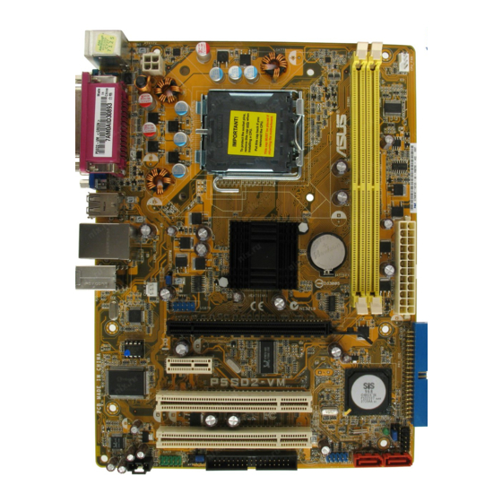
Page 19: Motherboard Layout
CMOS Power AUDIO USB78 Atheros PCIEX16 BIOS PCIEX1_1 P5SD2-VM Super I/O SIS 968 PCI1 PCI2 SB_PWR ALC662 CHASSIS FLOPPY USB56 SPDIF_OUT AAFP SATA2 SATA1 Refer to section 1.10 Connectors for more information about rear panel connectors and internal connectors. ASUS P5SD2-VM... -
Page 20: Layout Contents
1.5.4 Layout contents Slots Page DDR2 DIMM slots 1-16 PCI slots 1-24 PCI Express x1 slot 1-24 PCI Express x16 slot 1-24 Jumper Page 1. Clear RTC RAM (3-pin CLRTC) 1-25 2. USB device wake-up (3-pin USBPW1-4, USBPW56, PS2-USBPW) 1-26 Rear panel connectors Page 1-27... -
Page 21: Central Processing Unit (Cpu)
ASUS will shoulder the cost of repair only if the damage is shipment/transit-related. • Keep the cap after installing the motherboard. ASUS will process Return Merchandise Authorization (RMA) requests only if the motherboard comes with the cap on the LGA775 socket. -
Page 22: Installing The Cpu
1.6.1 Installing the CPU To install a CPU: Locate the CPU socket on the motherboard. P5SD2-VM P5SD2-VM CPU Socket 775 Before installing the CPU, make sure that the cam box is facing towards you and the load lever is on your left. Press the load lever with your thumb (A), then move it to the left (B) until it is released from the retention tab. - Page 23 If installing a dual-core CPU, connect the chassis fan cable to the chassis fan connector to ensure system stability. The motherboard supports Intel LGA775 processors with Hyper-Threading ® Technology. Refer to the Appendix for more information on these CPU features. ASUS P5SD2-VM 1-11...
-
Page 24: Installing The Cpu Heatsink And Fan
1.6.2 Installing the CPU heatsink and fan The Intel ® LGA775 processor requires a specially designed heatsink and fan assembly to ensure optimum thermal condition and performance. • When you buy a boxed Intel processor, the package includes the CPU fan ®... - Page 25 Connect the CPU fan cable to the connector on the motherboard labeled CPU_FAN. CPU FAN PWR CPU FAN IN CPU FAN PW M +12V Rotation P5SD2-VM Do not forget to connect the CPU fan connector! Hardware monitoring errors can occur if you fail to plug this connector. ASUS P5SD2-VM 1-13...
-
Page 26: Uninstalling The Cpu Heatsink And Fan
1.6.3 Uninstalling the CPU heatsink and fan To uninstall the CPU heatsink and fan: Disconnect the CPU fan cable from the connector on the motherboard. Rotate each fastener counterclockwise. Pull up two fasteners at a time in a diagonal sequence to disengage the heatsink and fan assembly from the motherboard. - Page 27 The narrow end of the groove should point outward after resetting. (The photo shows the groove shaded for emphasis.) Refer to the documentation in the boxed or stand-alone CPU fan package for detailed information on CPU fan installation. ASUS P5SD2-VM 1-15...
-
Page 28: System Memory
System memory 1.7.1 Overview The motherboard comes with two Double Data Rate 2 (DDR2) Dual Inline Memory Modules (DIMM) sockets. A DDR2 module has the same physical dimensions as a DDR DIMM but has a 240-pin footprint compared to the 184-pin DDR DIMM. DDR2 DIMMs are notched differently to prevent installation on a DDR DIMM socket. - Page 29 Due to chipset limitation, DDR2-667 with CL=3 will be downgraded to run at DDR2-533 by default setting. If you want to operate with lower latency, adjust the memory timing manually. There will be 4MB reduction in total memory when enabling ASUS Thermostat function under Single Channel mode. ASUS P5SD2-VM...
- Page 30 Qualified Vendors Lists (QVL) DDR2 667 DIMM support DIMM support Size Vendor Model Brand Side(s) Part No. DIMM1 DIMM2 256MB Kingston KVR667D2N5/256 Elpida E2508AB-6E-E • • 256MB Kingston KVR667D2N5/256 Kingston D3216TLSAKL3U • • 256MB Kingston KVR667D2N5/256 Infineon HYB18T256800AF3SW65 33154 • •...
- Page 31 • AL7E8E63B-6E1K A3R12E3GEF637BLC5N • • AL7E8E63J-6E1 A3R12E3JFF717B9A01 • • 256MB Nanya NT256T64UH4A1FY-3C Nanya NT5TU32M16AG-3C • • 512MB Nanya NT512T64U88A1BY-3C Nanya NT5TU64M8AE-3C • • DDR2-667U 1G Hynix HY5PS12821BFP-E3 A • • 512MB TEAM TVDD512M667C5 TEAM T2D648MT-6 • • ASUS P5SD2-VM 1-19...
- Page 32 512MB AENEON AET660UD00-370A88S AENEON AET82F370A 0550 • • Visit the ASUS website (www.asus.com) for the latest QVL. Side(s): SS - Single-sided DS - Double-sided DIMM support: DIMM1 - Supports one module inserted into any slot as Single-channel memory configuration. DIMM2 - Supports one pair of modules inserted into the slots as Single-channel memory configuration.
-
Page 33: Installing A Dimm
DIMM. Support the DIMM lightly with your fingers when pressing the retaining clips. The DIMM might get damaged when it flips out with DDR2 DIMM notch extra force. Remove the DIMM from the socket. ASUS P5SD2-VM 1-21... -
Page 34: Expansion Slots
Expansion slots In the future, you may need to install expansion cards. The following sub-sections describe the slots and the expansion cards that they support. Make sure to unplug the power cord before adding or removing expansion cards. Failure to do so may cause you physical injury and damage motherboard components. -
Page 35: Interrupt Assignments
— — — — — Onboard LAN — — — shared — — — — Onboard IDE port shared — — — — — — — Onboard SATA port — shared — — — — — — ASUS P5SD2-VM 1-23... -
Page 36: Pci Slots
1.8.4 PCI slots The PCI slots support cards such as a LAN card, SCSI card, USB card, and other cards that comply with PCI specifications. The figure shows a LAN card installed on a PCI slot. 1.8.5 PCI Express x1 slot This motherboard supports PCI Express x1 network cards, SCSI cards and other cards that comply with the PCI Express... -
Page 37: Jumpers
6. Hold down the <Del> key during the boot process and enter BIOS setup to re-enter data. Except when clearing the RTC RAM, never remove the cap on CLRTC jumper default position. Removing the cap will cause system boot failure! CLRTC P5SD2-VM Normal Clear RTC (Default) Clear RTC RAM P5SD2-VM ASUS P5SD2-VM 1-25... - Page 38 Keyboard/mouse/USB device wake-up (3-pin USBPW1-4, USBPW56, PS2_USBPWR) This jumper allows you to enable or disable the keyboard/mouse/USB device wake-up feature. Set this jumper to +5V to wake up the computer from S1 sleep mode (CPU stopped, DRAM refreshed, system running in low power mode) using the connected keyboard, mouse or USB devices.
-
Page 39: 1.10 Connectors
4-channel and 6-channel configuration, the function of this port becomes Front Speaker Out. Microphone port (pink). This port connects a microphone. Refer to the audio configuration table below for the function of the audio ports in 2, 4, or 6-channel configuration. ASUS P5SD2-VM 1-27... - Page 40 Audio 2, 4, or 6-channel configuration Port Headset 4-speaker 6-speaker 2-speaker Light Blue Line In Surround Out Surround Out Lime Line Out Front Speaker Out Front Speaker Out Pink Mic In Center/Bass USB 2.0 ports 1 and 2. These two 4-pin Universal Serial Bus (USB) ports are available for connecting USB 2.0 devices.
-
Page 41: Internal Connectors
This connector is for the S/PDIF audio module to allow digital sound output. Connect one end of the S/PDIF audio cable to this connector and the other end to the S/PDIF module. P5SD2-VM SPDIF_OUT P5SD2-VM Digital Audio Connector The S/PDIF out module is purchased separately. ASUS P5SD2-VM 1-29... - Page 42 IDE connector (40-1 pin PRI_IDE) The onboard IDE connector is for the Ultra DMA 133/100/66 signal cable. There are three connectors on each Ultra DMA 133/100/66 signal cable: blue, black, and gray. Connect the blue connector to the motherboard’s IDE connector, then select one of the following modes to configure your device.
- Page 43 480 Mbps connection speed. USB78 USB56 P5SD2-VM P5SD2-VM USB 2.0 Connectors Never connect a 1394 cable to the USB connectors. Doing so will damage the motherboard! The USB module is purchased separately. ASUS P5SD2-VM 1-31...
- Page 44 Do not place jumper caps on the fan connectors! CPU_FAN CPU FAN PWR CPU FAN IN CPU FAN PWM CHA_FAN +12V Rotation P5SD2-VM P5SD2-VM Fan Connectors Only the CPU-FAN connector supports the ASUS Advanced Q-Fan feature 1-32 Chapter 1: Product introduction...
- Page 45 P5SD2-VM Front Panel Audio Connector • We recommend that you connect a high-definition front panel audio module to this connector to avail of the motherboard’s high-definition audio capability. • By default, this connector is set to HD Audio. ASUS P5SD2-VM 1-33...
- Page 46 10. ATX power connectors (24-pin EATXPWR, 4-pin ATX12V) These connectors are for ATX power supply plugs. The power supply plugs are designed to fit these connectors in only one orientation. Find the proper orientation and push down firmly until the connectors completely fit. ATX12V EATXPWR +12V DC...
-
Page 47: System Panel Connector (10-1 Pin Panel)
BIOS settings. Pressing the power switch for more than four seconds while the system is ON turns the system OFF. • Reset button (2-pin RESET) This 2-pin connector is for the chassis-mounted reset button for system reboot without turning off the system power. ASUS P5SD2-VM 1-35... - Page 48 1-36 Chapter 1: Product introduction...
-
Page 49: Chapter 2: Bios Setup
This chapter tells how to change the system settings through the BIOS Setup menus. Detailed descriptions of the BIOS parameters are also provided. BIOS setup... -
Page 50: Managing And Updating Your Bios
The following utilities allow you to manage and update the motherboard Basic Input/Output System (BIOS) setup. ASUS EZ Flash (Updates the BIOS during the post using a floppy disk or the motherboard support CD.) ASUS AFUDOS (Updates the BIOS in DOS mode using a bootable floppy disk.) - Page 51 Right-click Floppy Disk Drive then click Format to display the Format 3 1/2 Floppy dialog box . d. Select the Create an MS-DOS startup disk check box. e. Click Start. Copy the original or the latest motherboard BIOS file to the bootable floppy disk. ASUS P5SD2-VM...
-
Page 52: Update Bios Using Ez Flash
2.1.2 ASUS EZ Flash utility The ASUS EZ Flash feature allows you to update the BIOS without having to go through the long process of booting from a floppy disk and using a DOS-based utility. The EZ Flash utility is built-in the BIOS chip so it is accessible by pressing <Alt>... -
Page 53: Afudos Utility
Extension name Press <Enter>. The utility copies the current BIOS file to the floppy disk. A:\>afudos /oOLDBIOS1.rom AMI Firmware Update Utility - Version 2.29(ASUS V2.07(03.11.24BB)) Copyright (C) 2002 American Megatrends, Inc. All rights reserved. Reading flash ..done Write to file..ok A:\>... -
Page 54: Updating The Bios File
Updating the BIOS file To update the BIOS file using the AFUDOS utility: Visit the ASUS website (www.asus.com) and download the latest BIOS file for the motherboard. Save the BIOS file to a bootable floppy disk. Write the BIOS filename on a piece of paper. You need to type the exact BIOS filename at the DOS prompt. -
Page 55: Asus Crashfree Bios 2 Utility
2.1.4 ASUS CrashFree BIOS 2 utility The ASUS CrashFree BIOS 2 is an auto recovery tool that allows you to restore the BIOS file when it fails or gets corrupted during the updating process. You can update a corrupted BIOS file using the motherboard support CD or the floppy disk that contains the updated BIOS file. -
Page 56: Recovering The Bios From The Support Cd
Restart the system after the utility completes the updating process. The recovered BIOS may not be the latest BIOS version for this motherboard. Visit the ASUS website (www.asus.com) to download the latest BIOS file. Chapter 2: BIOS setup... -
Page 57: Asus Update Utility
2.1.5 ASUS Update utility The ASUS Update is a utility that allows you to manage, save, and update the motherboard BIOS in Windows environment. The ASUS Update utility allows you ® • Save the current BIOS file • Download the latest BIOS file from the Internet •... - Page 58 To update the BIOS through the Internet: desktop by clicking Start Launch the ASUS Update utility from the Windows ® > Programs > ASUS > ASUSUpdate > ASUSUpdate. The ASUS Update main window appears. Select Update BIOS from Select the ASUS FTP site nearest...
- Page 59 To update the BIOS through a BIOS file: desktop by clicking Start Launch the ASUS Update utility from the Windows ® > Programs > ASUS > ASUSUpdate > ASUSUpdate. The ASUS Update main window appears. Select Update BIOS from a file option from the drop-down menu, then click Next.
-
Page 60: Bios Setup Program
The BIOS setup screens shown in this section are for reference purposes only, and may not exactly match what you see on your screen. • Visit the ASUS website (www.asus.com) to download the latest BIOS file for this motherboard. 2-12... -
Page 61: Bios Menu Screen
At the bottom right corner of a menu screen are the navigation keys for that particular menu. Use the navigation keys to select items in the menu and change the settings. Some of the navigation keys differ from one screen to another. ASUS P5SD2-VM 2-13... -
Page 62: Menu Items
2.2.4 Menu items The highlighted item on the menu bar displays the specific items for that menu. System Time [18:25:08] Use [ENTER], [TAB] System Date [Sun 01/06/2002] or [SHIFT-TAB] to Legacy Diskette A [1.44M, 3.5 in.] select a field. For example, selecting Main shows the Main Primary IDE Master :[Not Detected] Use [+] or [-] to... -
Page 63: Main Menu
Allows you to set the system date. 2.3.3 Legacy Diskette A [1.44M, 3.5 in.] Sets the type of floppy drive installed. Configuration options: [Disabled] [360K, 5.25 in.] [1.2M, 5.25 in.] [720K, 3.5 in.] [1.44M, 3.5 in.] [2.88M, 3.5 in.] ASUS P5SD2-VM 2-15... -
Page 64: Primary And Sata Ide Master/Slave
2.3.4 Primary and SATA IDE Master/Slave While entering Setup, the BIOS automatically detects the presence of IDE devices. There is a separate sub-menu for each IDE device. Select a device item then press <Enter> to display the IDE device information. Primary IDE Master Select the type of device connected to... -
Page 65: Ide Configuration
Allows you to disable or enable the onboard PCI IDE controller. Configuration options: [Disabled] [Enabled] SATA Mode Selection [IDE] Allows you to disable or set the onchip Serial ATA controller mode. Configuration options: [Disabled] [IDE] [Raid] [AHCI] ASUS P5SD2-VM 2-17... -
Page 66: System Information
2.3.6 System Information This menu gives you an overview of the general system specifications. The BIOS automatically detects the items in this menu. AMIBIOS Version : 0101 Build Date : 06/25/07 Processor Type : Genuine Intel(R) CPU 2.80GHz Speed 2800MHz Count : 2 System Memory Usable Size: 384MB... -
Page 67: Advanced Menu
USB Devices Enabled: None Legacy USB Support [Auto] USB 2.0 Controller Mode [HiSpeed] BIOS EHCI Hand-Off [Enabled] The Module Version and USB Devices Enabled items show the auto-detected values. If no USB device is detected, the item shows None. ASUS P5SD2-VM 2-19... -
Page 68: Cpu Configuration
OnBoard SiS USB 1.1/USB 2.0 Device [Enabled] Allows you to enable or disable the USB 1.1/USB 2.0 device. Configuration options: [Enabled] [Disabled] Legacy USB Support [Enabled] Allows you to enable or disable support for USB devices on legacy operating systems (OS). Setting to Auto allows the system to detect the presence of USB devices at startup. - Page 69 Allows you to Enable/disable the CPU TM function. Configuration options: [Disabled] [Enabled] Execute Disable Bit [Enabled] Allows you to Enable/disable Execute Disable Function. Configuration options: [Disabled] [Enabled] Single Logical Processor Mode [Disabled] Allows you to Enable/disable Single Logical Processor Mode. Configuration options: [Disabled] [Enabled] ASUS P5SD2-VM 2-21...
-
Page 70: Chipset
2.4.3 Chipset The Chipset menu allows you to change the advanced chipset settings. Select an item then press <Enter> to display the sub-menu. North Bridge SIS672 Configuration Options for NB South Bridge SIS968 Configuration North Bridge Configuration This will switch the Primary Graphics Adapter [PCI-E] PCI Bus scanning... -
Page 71: South Bridge Configuration
A11 PCI EXPRESS Controller [Enabled] Allows you to enable or disable the A11 PCI Express Controller. Configuration options: [Disabled] [Enabled] A11 PCI EXPRESS INTPIN [Disabled] Allows you to enable or disable the A11 PCI Express INTPIN. Configuration options: [Disabled] [Enabled] ASUS P5SD2-VM 2-23... -
Page 72: Onboard Devices Configuration
2.4.4 Onboard Devices Configuration Configure Win627DHG Super IO Chipset Allows BIOS to Serial Port1 Base Serial Port1 Address [3F8/IRQ4] Address. Parallel Port Address [378] Parallel Port Mode [ECP] ECP Mode DMA Channel [DMA3] Parallel Port IRQ [IRQ7] Serial Port1 Address [3F8/IRQ4] Allows you to select the Serial Port1 base addresses. -
Page 73: Pci Pnp
Configuration options: [Yes] [No] Palette Snooping [Disabled] When set to [Enabled], the pallete snooping feature informs the PCI devices that an ISA graphics device is installed in the system so that the latter can function correctly. Configuration options: [Disabled] [Enabled] ASUS P5SD2-VM 2-25... -
Page 74: Power Menu
IRQ-xx assigned to [PCI Device] When set to [PCI Device], the specific IRQ is free for use of PCI/PnP devices. When set to [Reserved], the IRQ is reserved for legacy ISA devices. Configuration options: [PCI Device] [Reserved] Power menu The Power menu items allow you to change the settings for the Advanced Power Management (APM). -
Page 75: Apm Configuration
Allows you to use specific keys on the keyboard to turn on the system. This feature requires an ATX power supply that provides at least 1A on the +5VSB lead. Configuration options: [Disabled] [Space Bar] [Ctrl-Esc] [Power Key] [Any Key] ASUS P5SD2-VM 2-27... -
Page 76: Hardware Monitor
Power On By PS/2 Mouse [Disabled] When set to [Enabled], this parameter allows you to use the PS/2 mouse to turn on the system. This feature requires an ATX power supply that provides at least 1A on the +5VSB lead. Configuration options: [Disabled] [Enabled] 2.5.6 Hardware Monitor... -
Page 77: Boot Menu
Select Item The number of device items that appears on the screen depends on the number of Enter Go to Sub-screen General Help devices installed in the system. Save and Exit Exit Configuration options: [xxxxx Drive] [Disabled] ASUS P5SD2-VM 2-29... -
Page 78: Boot Settings Configuration
This allows you to enable or disable the full screen logo display feature. Configuration options: [Disabled] [Enabled] Set this item to [Enabled] to use the ASUS MyLogo™ feature. Add On ROM Display Mode [Force BIOS] Sets the display mode for option ROM. -
Page 79: Security
<Enter>. The message “Password Uninstalled” appears. If you forget your BIOS password, you can clear it by erasing the CMOS Real Time Clock (RTC) RAM. See section “1.9 Jumpers” for information on how to erase the RTC RAM. ASUS P5SD2-VM 2-31... -
Page 80: Change User Password
After you have set a supervisor password, the other items appear to allow you to change other security settings. Security Settings Supervisor Password : Not Installed User Password : Not Installed Change Supervisor Password User Access Level [Full Access] Change User Password Clear User Password Password Check [Setup]... -
Page 81: Exit Menu
Setup menus. When you select this option or if you press <F5>, a confirmation window appears. Select OK to load default values. Select Exit & Save Changes or make other changes before saving the values to the non-volatile RAM. ASUS P5SD2-VM 2-33... - Page 82 2-34 Chapter 2: BIOS setup...
-
Page 83: Chapter 3: Software Support
This chapter describes the contents of the support CD that comes with the motherboard package. Software support... -
Page 84: Installing An Operating System
The contents of the support CD are subject to change at any time without notice. Visit the ASUS website(www.asus.com) for updates. 3.2.1 Running the support CD Place the support CD to the optical drive. The CD automatically displays the Drivers menu if Autorun is enabled in your computer. -
Page 85: Drivers Menu
The drivers menu shows the available device drivers if the system detects installed devices. Install the necessary drivers to activate the devices. ASUS InstAll - Drivers Installation Wizard Installs the ASUS Install - Drivers installation wizard. Realtek Audio Driver Installs the Realtek Audio Driver. -
Page 86: Utilities Menu
This utility helps you keep your computer in healthy operating condition. ASUS Update The ASUS Update utility allows you to update the motherboard BIOS in Windows ® environment. This utility requires an Internet connection either through a network... - Page 87 You can also install the following utilities from the ASUS Superb Software Library CD. ADOBE Acrobat Reader V7.0 Installs the Adobe® Acrobat® Reader that allows you to open, view, and print documents in Portable Document Format (PDF). Microsoft DirectX 9.0c Installs the Microsoft®...
-
Page 88: Make Disk Menu
3.2.4 Make Disk menu The Make Disk menu allows you to make a RAID driver disk Make SiS RAID Controller Driver disk Allows you to create an SiS RAID Controller driver disk 3.2.5 Manual menu The Manual menu contains a list of supplementary user manuals. Click an item to open the folder of the user manual. -
Page 89: Asus Contact Information
3.2.6 ASUS Contact information Click the Contact tab to display the ASUS contact information. You can also find this information on the inside front cover of this user guide. ASUS P5SD2-VM... - Page 90 Chapter 3: Software support...
-
Page 91: Cpu Features
The Appendix describes the CPU features and technologies that the motherboard supports. CPU features... -
Page 92: Appendix: Cpu Features
® Technology (EIST) • The motherboard comes with a BIOS file that supports EIST. You can download the latest BIOS file from the ASUS website (www.asus.com/support/download/) if you need to update the BIOS. See Chapter 2 for details. • Visit www.intel.com for more information on the EIST feature. - Page 93 Click Apply, then click OK. 10. Close the Display Properties window. After you adjust the power scheme, the CPU internal frequency slightly decreases when the CPU loading is low. The screen displays and procedures may vary depending on the operating system. ASUS P5SD2-VM...
-
Page 94: Intel ® Hyper-Threading Technology
Intel Hyper-Threading Technology ® • The motherboard supports Intel Pentium 4 LGA775 processors with ® ® Hyper-Threading Technology. • Hyper-Threading Technology is supported under Windows XP/2003 Server ® and Linux 2.4.x (kernel) and later versions only. Under Linux, use the Hyper-Threading compiler to compile the code.