Table of Contents
Advertisement
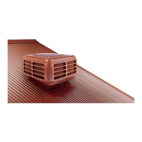
Installation Manual
C & A Series Evaporative Air Coolers
This appliance shall be installed in accordance with:
• Manufacturer's Installation Instructions
• Current AS/NZS 3000
• Local Regulations and Municipal Building Codes including local OH&S requirements
This appliance must be installed, maintained and removed by an Authorised Person.
For continued safety of this appliance it must be installed and maintained in
accordance with the manufacturers instructions.
Advertisement
Table of Contents

Related Manuals for Rinnai A20


Summary of Contents for Rinnai A20
-
Page 1: Installation Manual
Installation Manual C & A Series Evaporative Air Coolers This appliance shall be installed in accordance with: • Manufacturer’s Installation Instructions • Current AS/NZS 3000 • Local Regulations and Municipal Building Codes including local OH&S requirements This appliance must be installed, maintained and removed by an Authorised Person. For continued safety of this appliance it must be installed and maintained in accordance with the manufacturers instructions. -
Page 2: Table Of Contents
3.4 Dropper Duct Installation Guidelines ..........................8 4. Installation - C Series 4.1 Dropper Duct Installation and Fitting the Cooler ......................9 4.2 Fitting the Rinnai C Series cooler ..........................10 5. Installation - A Series 5.1 A Series Dropper Duct Specific ............................11 5.2 Fitting A Series Optional Winter-Seal ..........................11... - Page 3 10.2 Checklist ..................................18 10.3 What if the Fan Motor will not start? ..........................18 Check: ..................................... 18 10.4 What if the Pump will not start? ........................... 18 Check: ..................................... 18 11. Exhaust and Ventilation 12. Technical Specifications Contacts Rinnai Evap AC IM...
- Page 4 This page intentionally blank Rinnai Evap AC IM...
-
Page 5: Warnings And Important Information
SHOULD: INDICATES A RECOMMENDED REQUIREMENT OF THIS MANUAL. Any deviations from these instructions may, at the discretion of Rinnai, void the warranty. As a result, the customer and/or installer may be charged a fee for product non-warranty related call outs. Also, note that failure to comply with these instructions may preclude Rinnai from being able to service the unit. -
Page 6: General Guidelines
Carefully remove the outer packaging and any retaining brackets/straps that secure the cooler to the pallet. Rinnai coolers MUST BE installed in accordance with these instructions and related regulations, codes, standards, and authorities. These include but may not be limited to: •... -
Page 7: Cooler Service Requirements
DO NOT remove water supply line, (braided hose) from rear of cooler. 2.3 INSTALLING THE WALL CONTROL The Rinnai Networker and Manual Wall Control are part of a sophisticated control system. Controllers with Auto mode constantly monitor the temperature inside the house, switching the Cooler ON and OFF to maintain the target comfort level selected. -
Page 8: Cooler Hardware
It should also be as far down the roof as practicable. • Rinnai recommend installing a diffuser or cone in the base of the dropper box. This will assist distributing the airflow evenly into the duct system and can also reduce noise levels. -
Page 9: Installation - C Series
The dropper duct size for all Rinnai C Series models is 550mm X 550mm. • Rinnai C Series Coolers MUST use a dropper duct with an out turned flange (15-20mm). This is installed on an angle through the roof. •... -
Page 10: Fitting The Rinnai C Series Cooler
4. COOLER INSTALLATION 4.2 FITTING THE RINNAI C SERIES COOLER • The Cooler should now be mounted into position. Insert the Cooler’s air outlet fully into the dropper duct. • Ensure the Cooler base sits fully on the dropper box flange and that the base latching brackets (four) retract over the flange on both sides of the dropper, to lock it onto the dropper duct. -
Page 11: Installation - A Series
5.3 FITTING THE RINNAI A SERIES COOLER • The Rinnai A Series Cooler chassis comprises latching brackets to secure the unit to the dropper box. To assist with connection it is important the dropper box has a 15-20mm outward turned flange. -
Page 12: Network Connection
Networker needs to be configured. A Master Rinnai Networker can be identified by the word “clock” beside Key 5 (while the Rinnai Networkers are in the off position). Initially, both Rinnai Networkers upon power up will have the word “clock” beside key 5, because they are both still Masters at this stage. -
Page 13: Master And Slave Addressing
Installer set-up program. This Rinnai Networker will now become the Slave Rinnai Networker, and the installer parameters can no longer be accessed from this Rinnai Networker. The Master Rinnai Networker MUST now be used to access the installer parameters. -
Page 14: Changing An Identification Number
Turn the power supply at the Cooler OFF to save the new ID number. • Repeat the sequence for each Cooler. • Then follow the Rinnai Networker Advanced Programming Instructions to allocate the Coolers to their respective zones. Rinnai Evap AC IM... -
Page 15: Water Connection
The Rinnai A Series and Rinnai C Series electronic water level sensor automatically maintains the correct water level within the tank. The Rinnai A Series model is programmed to periodically flush the tank and refill it with clean water, depending on the operating conditions, and automatically maintain the water quality within the tank. The Rinnai C Series is fitted with an AquaSave module that maintains water purity during the cooler’s operation and... -
Page 16: Timing & Cooler Functions
During the Cooler’s operation with the pump operating, the Cooler will be evaporating water from the tank and automatically refilling itself. Rinnai A Series models will periodically, after a specified number of tank refills, flush out the tank (discharging water from the drain outlet for approximately 1 minute) without stopping the Cooler. -
Page 17: Dismantling
Lift up and remove the 4 PVC support posts, disengaging the pad’s restraining angle brackets. • Slide the side pad frames out from the formed brackets at the base of the frames. • Remove the side pad frames and external panel assemblies. Rinnai Evap AC IM... -
Page 18: Commissioning Checklist
10.1 ISOLATING SWITCH The Rinnai A Series and Rinnai C Series both have an external power-isolating switch to facilitate servicing. The switch is located under the front left hand side of the cooler. To access the switch, reach under the front of the Cooler’s trough and locate the switch. - Page 19 The pump is not in a delay due to ServoSeal damper, or tank filling operation. • The pump impeller is not blocked or obstructed. • All electrical connections are secure, and if the pump will not start, call Rinnai for service. Rinnai Evap AC IM...
-
Page 20: Exhaust And Ventilation
Four sliding windows or one door and four hinged windows 2.8 m 1.7 m Five sliding windows or one door and five hinged windows 3.1 m 1.9 m Six sliding windows or one door and six hinged windows 3.4 m 2.1 m Rinnai Evap AC IM... -
Page 21: Technical Specifications
12. TECHNICAL SPECIFICATIONS Rinnai Evap AC IM... - Page 22 NOTES Rinnai Evap AC IM...
- Page 23 NOTES Rinnai Evap AC IM...
-
Page 24: Contacts
Braeside, Victoria 3195 For further information visit: www.rinnai.com.au Rinnai has a Service and Spare Parts network with personnel who are fully trained and equipped to give the best service on your Rinnai appliance. If your appliance requires service, please call our National Help Line. Rinnai recommends that this appliance be serviced every 2 years.