Advertisement
Available languages
Available languages
UK
-
Installation and operating instructions
FR
-
Manuel d'installation et d'utilisation
ES
-
Instrucciones para instalación
IT
-
Manuale di installazione ed uso
NL
-
Installatie- en montagehandleiding
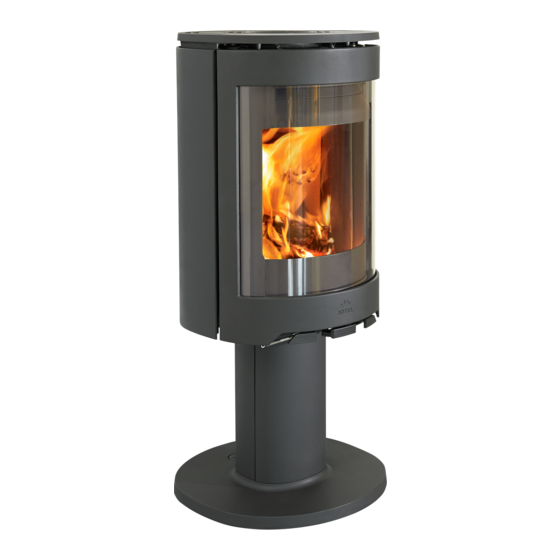
Jøtul F 481
Jøtul F 483
The manuals which are enclosed with the product must be kept throughout the product's entire service
manuels fournis avec le produit doivent être conservés pendant toute la durée de vie du produit. I manuali inclusi
con il prodotto vanno conservati per l'intera durata di vita del prodotto.
Jøtul
F 480
2
18
35
52
69
life.Les
Advertisement
Chapters

Related Manuals for Jøtul F481


Summary of Contents for Jøtul F481
- Page 1 Jøtul F 480 Installation and operating instructions Manuel d’installation et d’utilisation Instrucciones para instalación Manuale di installazione ed uso Installatie- en montagehandleiding Jøtul F 481 Jøtul F 483 The manuals which are enclosed with the product must be kept throughout the product’s entire service life.Les manuels fournis avec le produit doivent être conservés pendant toute la durée de vie du produit.
-
Page 2: Table Of Contents
ENGLISH Table of contents 1.0 Technical data Material: Cast iron Technical data ......... 2 Finish: Black paint Type of fuel: Wood Max. log length: 30 cm Relationship to the authorities ....2 Smoke outlet: Top, rear Flue pipe dimension: Ø 150 mm Safety ............ -
Page 3: Safety
ENGLISH 3.0 Safety Requirements for protection of infl ammable fl oors in front of the fi replace NB! To guarantee optimal performance and safety, Jøtul The front plate must comply with national laws and regulations. recommends that its stoves are fi tted by a qualifi ed Contact your local building authorities regarding restrictions installer (see www.jotul.com for a complete list of dealers). - Page 4 ENGLISH...
- Page 5 ENGLISH...
-
Page 6: Installation
ENGLISH Air supply 4.0 Installation The amount of combustion air for Jøtul’s products is approximately 20-40 m 3 /h. The outside air connection may be fi tted directly to NB: Check that the fi replace is undamaged before installation the Jøtul F 480 through: begins. - Page 7 ENGLISH 4.2 Installation Installation of base/pedestal on the burnchamber External air supply through the base Fig. 5 Through the fl oor 1. NB! If connecting the Flex Hose through a hole in the fl oor, do not knock out the removable cover plates (Fig. 5 A). Through the rear outlet in the base Fig.
- Page 8 ENGLISH Fig. 9 4.9 Location of approval label The approval label must always be affixed to the wire and positioned as illustrated in fi g. 11. Fig. 11, Base 6. Loosen the height adjustment screws slightly (A) beneath the product so that they can be screwed by hand. NB: If the optional glass fl...
- Page 9 ENGLISH Installation with external air supply 4.3 Chimney and fl ue pipe • The fi replace must only be connected to a chimney and Fig. 12 - Base fl ue pipe approved for solid fuel fi replaces with fl ue gas temperatures as specifi...
- Page 10 ENGLISH Fig. 14 Fitting a fl ue pipe with a top outlet With a top outlet, the fl ue pipe is installed after the outer sides have been installed. See Chapter 4.6. Fitting a fl ue pipe with a rear outlet The product is supplied from the factory with the smoke outlet fi...
- Page 11 ENGLISH 4.5 Installing the cast iron sides 4.6 Fitting a fl ue pipe with a top outlet The product is supplied from the factory with the smoke outlet Fig. 16 fi tted for the top outlet. 1. Place the product in the correct position (fi g. 1). 2.
-
Page 12: Daily Use
ENGLISH 4.8 Performance check 5.0 Daily use Always check the control handles once the product has been assembled. These should move easily and work in a Odours when using the fi replace for the satisfactory manner. fi rst time Fig. 19 When the fi... -
Page 13: Maintenance
ENGLISH 5.2 Ash removal Initial lighting • Open the air vent and ignition vent by pulling the handles • The Jøtul F 480 has an ash pan that makes it easy to (fi g. 19 A and B) all the way out. (Use a glove or something remove the ash. -
Page 14: Servicing
ENGLISH 6.5 Exterior maintenance place, check that the gasket on the back burn plate is securely attached. Painted products may change colour after several years’ 8. Lift out the riddling grate (J) (can be done fi rst when it usage. The surface should be cleaned and brushed free of needs replacing). - Page 15 ENGLISH Fig. 23 Fig. 25 9. Place the glass holders on a soft material with the side, as illustrated (A), turned up. 10. Apply a bead of glue into the gasket groove (B) which is now facing up. 11. Fit the gasket (C) into the groove with the ends sticking out 4.
- Page 16 ENGLISH 7.4 Adjusting the door Fig. 28 Fig. 27 4. Loosen the screws (Fig. 28 A). 5. Place the door in the required position. 6. Tighten the screws (Fig. 28 A) and in Fig. 27 C. 7. Loosen the screws in Fig. 27 D and Fig. 28 B. 8.
-
Page 17: Optional Extras
ENGLISH 8.0 Optional extras 9.0 Recycling 8.1 Outside air connection 9.1 Recycling packaging Outside air connection, Ø 80 mm - Cat. no. 51047509 Your fi replace is delivered with the following packaging: • A wooden pallet that can be cut up and burned in the fi... -
Page 18: Données Techniques
FRANCAIS Sommaire 1.0 Données techniques Matériau : Fonte Données techniques ......18 Finition : Peinture noire Combustible : Bois exclusivement Longueur maximale des bûches : 30 cm Relations avec les autorités ....18 Sortie du conduit de raccordement : Haut, arrière Conduit de raccordement : Ø... -
Page 19: Sécurité
FRANCAIS 3.0 Sécurité 3.2 Le sol Remarque : Afi n d’assurer un niveau de rendement et de sécurité optimal, l’installation d’un poêle Jøtul doit être Assurez-vous que le sol convient pour un poêle. Se reporter confi ée à un installateur qualifi é (voir www.jotul.com pour à... - Page 20 FRANCAIS...
- Page 21 FRANCAIS...
-
Page 22: Installation
FRANCAIS Arrivée d’air 4.0 Installation Le volume d’air de combustion des produits Jøtul est d’environ 20 à 40 m 3 /h. L’arrivée d’air frais peut être raccordée Remarque : Assurez-vous que l’appareil est en bon état avant de procéder à l’installation. directement au poêle Jøtul F 480 par : •... - Page 23 FRANCAIS 4.2 Installation Montage de la base/du piètement sur le poêle Air de combustion par la base Fig. 6 A travers le sol 1. Remarque : Si vous choisissez de faire passer le conduit fl exible à travers le plancher, ne retirez pas les caches amovibles (Fig.
- Page 24 FRANCAIS 4.3 Emplacement de la plaque Fig. 9 signalétique La plaque signalétique doit toujours être apposée sur le fi l et positionnée comme illustré dans la Fig. 11. Fig. 11, Base 6. Desserrez légèrement les vis de réglage du niveau (A) en dessous de l’appareil de façon à...
- Page 25 FRANCAIS 4.4 Cheminées et conduits Installation avec une arrivée d’air frais • Le poêle peut être relié à une cheminée et à un conduit Fig. 12 - Base approuvés pour les poêles à combustible solide, avec les températures de fumées spécifi ées dans la section «1.0 Données techniques».
- Page 26 FRANCAIS Montage d’un conduit de fumée avec sortie par Fig. 14 le haut Avec une sortie par le haut, le conduit d’évacuation est monté après que les plaques extérieures aient été installées. Voir Chapitre 4.6. Montage d’un conduit de fumée avec sortie arrière Le produit est livré...
- Page 27 FRANCAIS 4.5 Montage des plaques latérales en 4.6 Montage d’un conduit de fumée avec fonte sortie par le haut Remarque : Avec une sortie par le haut, le conduit Fig. 16 d’évacuation est installé après que les plaques extérieures ont été...
-
Page 28: Utilisation Au Quotidien
FRANCAIS 4.8 Test de fonctionnement 5.0 Utilisation au quotidien Inspectez toujours les poignées de commande une fois l’appareil monté. Les éléments mobiles doivent fonctionner Odeurs perceptibles lors de la première librement. utilisation du poêle Fig. 19 Lors de la première utilisation, le poêle peut émettre un gaz irritant et dégager des odeurs désagréables. - Page 29 FRANCAIS 5.1 Risque de surchauffe Bois d’allumage (bois fendu menu) : Longueur : environ 30 cm Diamètre : 2 à 5 cm Ne surchauffez jamais le poêle Quantité nécessaire à l’allumage : 6 à 8 morceaux La surchauffe est provoquée par un excès de combustible et/ou d’air qui donne lieu à...
-
Page 30: Maintenance
FRANCAIS 6.0 Maintenance 7.0 Entretien Avertissement ! Toute modifi cation non autorisée du 6.1 Nettoyage de la vitre produit est interdite ! Utilisez uniquement des pièces détachées d’origine ! Le poêle est équipé d’un système d’entrée d’air par le haut. L’air est aspiré... - Page 31 FRANCAIS de la grille de décendrage touche la barre sous la plaque Fig. 23 de fond inférieure au moment de la remise en place. 9. Soulevez et sortez la plaque de fond intérieure (K). 10. Maintenir la conduite d’air supérieure (L) en hauteur au niveau du bord avant en desserrant la vis (M).
- Page 32 FRANCAIS Fig. 25 7.4 Ajuster la porte Fig. 27 9. Placez les supports de vitre sur un matériau avec le côté, comme illustré (A) tourné vers le haut. 10. Appliquez un cordon de colle dans la rainure du joint (B) qui est maintenant tournée vers le haut.
-
Page 33: Équipements Disponibles En Option
FRANCAIS Fig. 28 8.0 Équipements disponibles en option 8.1 Raccordement prise d’air extérieur Raccordement prise d’air extérieur, Ø 80 mm - Réf. cat. 51047509. 8.3 Ensemble tournant Voir guide d’installation spécial (réf. cat. 10026061). Ensemble tournant pour les modèles Jøtul F 363, Jøtul F 373, Jøtul F 483 SHD et Jøtul F 483 –... -
Page 34: Recyclage
FRANCAIS 9.0 Recyclage 10.0 Garantie La société Jøtul offre une garantie sur les pièces extérieures en 9.1 Recyclage de l’emballage fonte en cas de vice de matière et/ou de fabrication à compter de la date de l’achat / de l’installation du poêle. L’acheteur •... - Page 35 ESPAÑOL Indice 1.0 Datos técnicos Material: Hierro colado Datos técnicos ........35 Acabado: Pintura negra Tipo de combustible: Madera Longitud máx. de leño: 30 cm Relación con las autoridades ....35 Salida de humo: Superior, trasera Tamaño del tubo de tiro: Ø 150 mm Seguridad ..........36 Conexión de aire exterior: Alum.
- Page 36 ESPAÑOL 3.0 Seguridad 3.2 Suelo N. B.: para garantizar un rendimiento y seguridad óptimos, Anclaje, base Jøtul recomienda que sus estufas sean instaladas por Debe verifi car que la base se adecue a la instalación de un instalador cualifi cado (consulte la lista íntegra de una estufa.
- Page 37 ESPAÑOL...
- Page 38 ESPAÑOL...
- Page 39 ESPAÑOL Suministro de aire 4.0 Instalación El volumen de aire de combustión para los productos de Jøtul es de aproximadamente 20-40 m 3 /h. Nota: Compruebe que la estufa esté intacta antes de iniciar la instalación. La conexión de aire exterior debe conectarse directamente a la Jøtul F 480 a través de: Nota: ¡Atención! El producto es pesado.
- Page 40 ESPAÑOL 4.2 Instalación Instalación de la base/pedestal en la cámara de combustión Conexión de aire exterior a travez del sócalo Fig. 6 A través del suelo 1. N. B.: Si conecta el manguito fl exible a través de un agujero en el piso, no retire las placas de cubierta desmontables (Fig.
- Page 41 ESPAÑOL 4.9 Ubicación de la etiqueta de Fig. 9 aprobación La etiqueta de aprobación debe fi jarse siempre al cable y colocarse según se ilustra en la Fig. 11. Fig. 11, Base 5. Afl oje ligeramente los tornillos de ajuste (A) de la altura bajo el producto de forma que puedan girarse con la mano.
- Page 42 ESPAÑOL Instalación con suministro de aire externo 4.3 Chimenea y tubo del tiro • La estufa solo debe conectarse a una chimenea y tubo de Fig. 12 - Base tiro homologados para estufas de combustible sólido con temperaturas de gas de tiro conforme a lo especifi cado en «1.0 Datos técnicos».
- Page 43 ESPAÑOL Instalación de tubo de tiro con salida Fig. 14 superior Con una salida superior, el tubo de tiro se instala después de instalar los lados exteriores. Véase el Capítulo 4.5. Instalación de tubo de tiro con salida trasera El producto está equipado de fábrica con una salida de humos instalada en la salida superior.
- Page 44 ESPAÑOL 4.5 Instalación de laterales de hierro 4.6 Instalación de tubo de tiro con salida fundido superior El producto está equipado de fábrica con una salida de humos Fig. 16 instalada en la salida superior. 1. Coloque el producto en la posición correcta (Fig. 1). 2.
- Page 45 ESPAÑOL 5.0 Uso diario 4.8 Comprobación del rendimiento Compruebe siempre los manillares de control después de ensamblar el producto. Deben moverse con facilidad y operar Olores al usar la estufa por primera vez de modo satisfactorio. Cuando se usa la estufa por primera vez, puede emitir un gas irritante que huela ligeramente.
- Page 46 ESPAÑOL 5.2 Retirada de cenizas Encendido inicial • Abra el respiradero de aire y el respiradero de encendido La Jøtul F 480 tiene una bandeja de cenizas que permite retirar tirando de los manillares (Fig. 19 A y B) hasta el tope. las cenizas con facilidad.
- Page 47 ESPAÑOL 6.4 Inspección de la estufa 7.0 Servicio Jøtul le recomienda que inspeccione detenidamente la estufa ¡Advertencia! Es ilegal cualquier modifi cación no después de limpiarla/deshollinarla. Revise todas las superfi cies autorizada del producto. Solo podrán usarse piezas de visibles en busca de grietas. Compruebe también que estén repuesto originales.
- Page 48 ESPAÑOL vez cuando sea necesario sustituirla). Compruebe que la Fig. 23 ranura de la rejilla de criba esté contra la barra debajo de la placa inferior interna al volver a montarla en su lugar. 9. Levante la placa inferior interna (K) y sáquela. 10.
- Page 49 ESPAÑOL Fig. 25 7.4 Ajuste de la puerta Fig. 27 9. Coloque los soportes del cristal sobre un material con el lado hacia arriba, como muestra la ilustración (A). 10. Aplique una gota de adhesivo en la ranura de la junta (B) que ahora está...
- Page 50 ESPAÑOL Fig. 28 8.0 Complementos opcionales 8.1 Conexión de aire exterior Conexión de aire exterior, Ø 80 mm - N.º cat. 51047509 8.2 Juego giratorio Consulte las instrucciones de instalación separadas - N.º cat. 10026061. Juego giratorio para Jøtul F 373, Jøtul F 363, Jøtul F 473 SHD y Jøtul F 483 - N.º...
- Page 51 ESPAÑOL 9.0 Reciclaje 10.0 Garantía Jøtul AS ofrece a sus clientes una garantía de diez años, con 9.1 Reciclaje del embalaje derecho a devolver los elementos externos de hierro fundido si presentan defectos como resultado de materiales y/o mano de •...
-
Page 52: Dati Tecnici
ITALIANO Indice generale 1.0 Dati tecnici Materiale: Ghisa Dati tecnici ..........52 Finitura: Vernice nera Tipo di combustibile: Legna Lunghezza massima ceppi: 30 cm Conformità alle normative ...... 52 Scarico fumi: Superiore, posteriore Dimensioni condotto: Ø 150 mm Sicurezza ..........53 Condotto per l'aria esterna: Alu. - Page 53 ITALIANO 3.0 Sicurezza Requisiti per la protezione del pavimento in legno sotto il caminetto Nota: per garantire prestazioni e sicurezza ottimali, le Il prodotto presenta una protezione integrata del pavimento, stufe Jøtul devono essere montate da un installatore pertanto può essere posizionato direttamente su un pavimento qualifi...
- Page 54 ITALIANO...
- Page 55 ITALIANO...
- Page 56 ITALIANO Circolazione dell'aria 4.0 Installazione Il quantitativo di aria di combustione per i prodotti Jøtul è di circa 20-40 m 3 /h. Nota: prima di iniziare l'installazione, assicurarsi che il Il condotto per l'aria esterna può essere inserito direttamente caminetto non sia danneggiato. in Jøtul F 480 attraverso: •...
- Page 57 ITALIANO 4.2 Installazione Installazione della base/piedistallo sulla camera di combustione Aria di combustione diretta attraverso la base. Fig. 6 Attraverso il pavimento 1. Nota: in caso di collegamento del tubo fl essibile attraverso un foro nel pavimento, non estrarre le piastre di copertura rimovibili (Fig.
- Page 58 ITALIANO Fig. 9 4.3 Posizione dell’etichetta di conformità L’etichetta di conformità deve sempre essere applicata al cavo e posizionata come illustrato nella Fig. 11. Fig. 11, Base 6. Allentare leggermente le viti di regolazione dell'altezza (A) sotto il prodotto, in modo che possano essere avvitate a mano.
- Page 59 ITALIANO Installazione con circolazione dell'aria 4.4 Canna fumaria e condotto esterna • Il caminetto deve essere collegato solo a una canna fumaria e a un condotto approvati per caminetti a combustibile Fig. 12 - Base solido; le temperature dei gas prodotti dal fumo sono indicate nel capitolo "1.0 Dati tecnici".
- Page 60 ITALIANO Inserimento di un condotto con uno Fig. 14 scarico superiore In presenza di uno scarico superiore, il condotto viene montato dopo aver installato i lati esterni. Vedere il paragrafo 4.5. Inserimento di un condotto con uno scarico posteriore Il prodotto viene consegnato dalla fabbrica con uno scarico fumi adatto allo scarico superiore.
- Page 61 ITALIANO 4.5 Installazione dei lati in ghisa 4.6 Inserimento di un condotto con uno scarico superiore Fig. 16 Il prodotto viene consegnato dalla fabbrica con uno scarico fumi adatto allo scarico superiore. 1. Collocare il prodotto nella posizione corretta. 2. Posizionare la piastra superiore e la grata in cima al prodotto.
- Page 62 ITALIANO 4.8 Controllo delle prestazioni 5.0 Utilizzo giornaliero Una volta assemblato il prodotto, controllare sempre le manopole di regolazione. Devono muoversi facilmente e Odori al primo utilizzo del caminetto funzionare in modo soddisfacente. Quando il caminetto viene utilizzato per la prima volta, può Fig.
-
Page 63: Pulizia Del Vetro
ITALIANO Accensione iniziale 5.2 Rimozione della cenere Aprire le prese d'aria e di accensione estraendo completamente Jøtul F 480 include un ceneraio che semplifi ca la rimozione le manopole (Fig. 19 A e B). Se necessario, tenere la porta della cenere. leggermente aperta. - Page 64 ITALIANO 7.0 Assistenza 6.4 Ispezione del caminetto Jøtul raccomanda di ispezionare attentamente il proprio Avviso: è vietata ogni modifi ca non autorizzata al prodotto. caminetto dopo averlo spazzato e pulito. Controllare tutte le Utilizzare solo ricambi originali. superfi ci visibili per individuare eventuali crepe. Controllare anche che tutti i giunti siano sigillati e che tutte le guarnizioni siano nelle posizioni corrette.
- Page 65 ITALIANO Fig. 23 8. Sollevare ed estrarre la grata perforata (J) (farlo subito se deve essere sostituita). Accertarsi che l'alloggiamento sulla grata perforata si trovi contro la barra sotto la piastra inferiore interna quando viene reinserita. 9. Sollevare ed estrarre la piastra inferiore interna (K). 10.
- Page 66 ITALIANO Fig. 25 7.4 Regolazione della porta Fig. 27 9. Collocare i supporti del vetro su una superfi cie con il lato, come illustrato (A), e rivolti verso l’alto. 10. Applicare una goccia di colla nella scanalatura della guarnizione (B) rivolta adesso verso l’alto. 11.
- Page 67 ITALIANO Fig. 28 8.0 Accessori opzionali 8.1 Condotto per l'aria esterna Condotto per l'aria esterna, Ø 80 mm - N. cat. 51047509 8.2 Set girevole Consultare le istruzioni di installazione separate - n. cat. 10026061. Set girevole per Jøtul F 363, Jøtul F 373, Jøtul F 473 SHD e Jøtul F 483, n.
- Page 68 9.0 Riciclaggio 10.0 Garanzia Jøtul AS fornisce ai propri clienti una garanzia decennale 9.1 Riciclaggio dell’imballo che prevede il diritto alla restituzione degli elementi esterni in ghisa, qualora mostrino difetti nei materiali e/o nella Ogni caminetto viene fornito all’interno del seguente imballo: fabbricazione, dopo l'acquisto...
- Page 69 NEDERLANDS 1.0 Technische gegevens Inhoudsopgave Materiaal: Gietijzer Technische gegevens ......69 Afwerking: Zwarte verf Type brandstof: Hout Max. lengte van blokken: 30 cm Wettelijke voorschriften ......69 Rookuitlaat: Bovenkant, achterzijde Afmeting kachelpijp: Ø 150 mm Veiligheid ..........70 Externe luchtaansluiting: Alu.
- Page 70 NEDERLANDS 3.0 Veiligheid Eisen met betrekking tot het beschermen van een houten vloer onder de haard NB! Om optimale prestaties en veiligheid te garanderen, Het product beschikt over geïntegreerde vloerbescherming en raadt Jøtul aan haar kachels te laten monteren door een kan daarom direct op een houten vloer worden geplaatst.
- Page 71 NEDERLANDS...
- Page 72 NEDERLANDS...
- Page 73 NEDERLANDS Luchttoevoer 4.0 Installatie De hoeveelheid verbrandingslucht voor Jøtul-producten is ongeveer 20-40 m 3 /h. De externe luchtaansluiting kan direct NB: Controleer voordat u met de installatie begint of de haard onbeschadigd is. op de Jøtul F 480 worden aangesloten door middel van: •...
- Page 74 NEDERLANDS 4.2 Installatie Basis/voetstuk op de verbrandingskamer monteren Buitenlucht aansluiting door de sokkel Fig. 6 Via de vloer 1. NB! Sla de verwijderbare afdekplaten er niet uit als u de fl exibele slang door een gat in de vloer aansluit (fi g. 5 A). Fig.
- Page 75 NEDERLANDS Fig. 9 4.3 Locatie van goedkeuringsetiket Het goedkeuringsetiket moet altijd aan de draad zijn bevestigd en op de in Fig. 11 aangegeven plek zitten. Fig. 11, Basis 6. Draai de stelschroeven voor de hoogte onder het product iets los (A), zodat ze met de hand gedraaid kunnen worden. NB: Bij gebruik van de optionele glazen vloerplaat moet u de basis ongeveer 8 mm van de vloer optillen, zodat deze onder de voorrand van de basis kan worden...
- Page 76 NEDERLANDS Installatie met externe luchttoevoer 4.3 Schoorsteen en kachelpijp • De haard mag uitsluitend worden aangesloten op een Fig. 12 - Basis schoorsteen en kachelpijp die zijn goedgekeurd voor haarden op vaste brandstof met rookgastemperaturen zoals gespecifi ceerd in «1.0 Technische gegevens». •...
- Page 77 NEDERLANDS Een kachelpijp met een bovenuitlaat Fig. 14 verbinden Bij een bovenuitlaat wordt de kachelpijp geïnstalleerd nadat de buitenste zijkanten zijn geïnstalleerd. Zie Hoofdstuk 4.6. Een kachelpijp met een achteruitlaat verbinden Het product wordt door de fabriek geleverd met een rookuitlaat als bovenuitlaat.
- Page 78 NEDERLANDS 4.5 Gietijzeren zijkanten monteren 4.6 Een kachelpijp met een bovenuitlaat verbinden Fig. 16 Het product wordt door de fabriek geleverd met een rookuitlaat als bovenuitlaat. 1. Plaats het product in de juiste positie. 2. Plaats de bovenplaat en het rooster bovenop het product. 3.
- Page 79 NEDERLANDS 4.8 Prestatiecontrole 5.0 Dagelijks gebruik product gemonteerd, moet altijd bedieningshendels controleren. Deze moeten makkelijk Geur bij eerste gebruik van de haard bewegen en goed werken. Als de haard voor de eerste keer wordt gebruikt, kan irriterend gas vrijkomen dat onaangenaam kan ruiken. Dit gebeurt Fig.
- Page 80 NEDERLANDS Eerste keer stoken 5.2 As verwijderen Open de luchtopening en de ontstekingsopening door de De Jøtul F 480 heeft een aslade waarmee het eenvoudig is om hendels (Fig. 19 A en B) volledig uit te trekken. (Gebruik een as te verwijderen. handschoen of iets dergelijks om uw hand te beschermen als •...
- Page 81 NEDERLANDS 7.0 Groot onderhoud 6.4 Inspectie van de haard Jøtul raadt u aan om na het reinigen/vegen zelf een grondige Waarschuwing! Er mogen geen wijzigingen aan het inspectie van de haard uit te voeren. Controleer alle product worden uitgevoerd die niet door ons zijn zichtbare oppervlakken op scheuren.
- Page 82 NEDERLANDS 9. Hef de binnenste bodemplaat (K) op en verwijder deze. Fig. 23 10. Houd het bovenste luchtkanaal (L) aan de voorste rand omhoog en draai de schroef los (M). Gebruik een dopsleutel (13 mm) en een verlengstuk. Kantel het luchtkanaal naar beneden als de schroef los is.
- Page 83 NEDERLANDS Fig. 25 6.4 Deur afstellen Fig. 27 9. Plaats de glashouders zoals afgebeeld (A) met de zijkant omhoog op een materiaal. 10. Breng een druppel lijm aan in de nu naar boven wijzende groef van de pakking (B). 11. Plaats de pakking (C) in de groef en laat beide uiteinden zoals afgebeeld een stuk uitsteken (11 cm aan beide kanten).
- Page 84 NEDERLANDS Fig. 28 8.0 Optionele extra’s 8.1 Externe luchtaansluiting Externe luchtaansluiting, Ø 80 mm - Cat. nr. 51047509. 8.2 Draaiset Zie de aparte installatie-instructies (cat. nr. 10026061). Draaiset voor Jøtul F 363, Jøtul F 373,Jøtul F 473 SHD en Jøtul F 483 - Cat.
- Page 85 NEDERLANDS 9.0 Recycling 10.0 Garantie Jøtul AS biedt haar klanten een garantie van tien jaar inclusief 9.1 Recyclen van de verpakking het recht op teruggaaf van externe gietijzeren items ingeval deze defecten vertonen als gevolg van verkeerde materialen • Uw kachel wordt in de volgende verpakking geleverd: en/of fabricage na de initiële aankoop/installatie van de kachel.
- Page 87 Sluttkontroll av ildsteder Quality control of stoves and fireplaces Checked Utført Kontrollpunkt Controlled item Alle deler er med i produktet (ifølge struktur). All parts are included. Alle festemidler er av korrekt type, og er korrekt Correct fastener items have been used and anvendt.
- Page 88 Jøtul pursue a policy of constant product development. Products supplied may therefore differ in specifi cation, colour and type of accessories from those illustrated and described in the brochure. Jøtul vise sans cesse à améliorer ses produits. C’est pourquoi, il se réserve le droit de modifi er les specifi...