Table of Contents
Advertisement
Advertisement
Table of Contents

Related Manuals for Star Micronics FVP10 series


Summary of Contents for Star Micronics FVP10 series
- Page 1 THERMAL PRINTER FVP10 SERIES Hardware Manual...
- Page 2 Caution Symbol These symbols are located near the thermal print head. Because the thermal print head is hot immediately after printing, do not touch it. Static electricity can damage the thermal print head. To protect the thermal print head from static electricity, do not touch it.
-
Page 3: Trademark Acknowledgments
This statement will be applied only for the printers marketed in U.S.A and Canada. CE MARKING WARNING Hereby, Star Micronics Co., Ltd. declares that this device is in compliance with the essential requirements and other relevant provisions of Directive 1999/5/EC. -
Page 4: Table Of Contents
TABLE OF CONTENTS 1. Unpacking and Installation ..................1 1-1. Unpacking........................... 1 1-2. Notes about Installation ...................... 1 2. Parts Identification and Nomenclature ..............2 3. Setup ..........................3 3-1. Connecting the Interface Cable to the PC ................3 3-1-1. Parallel Interface Cable ......................3 3-1-2. - Page 5 4-4. Changing the Cutter Mode ....................21 4-5. Setup Precautions ......................22 5. Consumable Parts and AC Adapter ............... 24 5-1. General Thermal Paper Roll ..................... 24 Paper Roll Specifications 5-1-1....................24 Effective Print Width 5-1-2.....................25 5-2. Thermal Label Paper Roll (Tack label paper and full-face thermal label paper) ..... 25 Paper Roll Specifications 5-2-1.
- Page 6 10-2. Platen Rubber Roller ......................38 10-3. Paper Holder ........................38 10-4. Sensors and Their Surrounding Area ................38 11. Specifications ......................39 11-1. General Specifications ...................... 39 11-2. Auto Cutter Specifications ....................40 11-3. Interface Specifications ....................40 11-4. Power Supply Specifications .................... 40 11-5.
-
Page 7: Unpacking And Installation
1. Unpacking and Installation 1-1. Unpacking After unpacking the unit, check that all the necessary accessories are included in the package. Thermal paper roll CD-ROM Setup sheets Switch cover Printer USB cable 1-2. Notes about Installation 1. Place the printer on a firm, level desktop. 2. -
Page 8: Parts Identification And Nomenclature
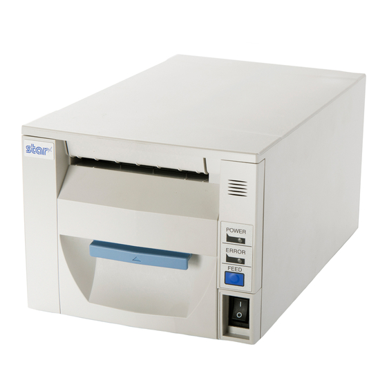
2. Parts Identification and Nomenclature Front cover Open to replace paper. Do not open while printing. Control panel Features LEDs that indicate Cover open lever printer status and a button for operating the printer. Pull the cover open lever toward you to open the front cover. -
Page 9: Setup
3. Setup 3-1. Connecting the Interface Cable to the PC 3-1-1. Parallel Interface Cable Connect the parallel interface cable to a parallel port on your PC. 3-1-2. RS-232C Interface Cable Connect the RS-232C interface cable to a RS-232C port on your PC. 3-1-3. USB Interface Cable Connect the USB interface cable to a USB port on your PC. Accessory: USB cable 1.8M with core TSP1 (P/N: 30729170) - 3 -... -
Page 10: Poweredusb Interface Cable
3-1-4. PoweredUSB Interface Cable To protect the printer from electromagnetic interference, affix the ferrite core that came with the optional PoweredUSB in- terface board to the cable. Then, connect the cable to a PoweredUSB port on your PC. Note: The optional PoweredUSB cable has been designed specifically for this printer. Other PoweredUSB cables may not meet the EMC technical standards. -
Page 11: Connecting The Interface Cable To The Printer
3-2. Connecting the Interface Cable to the Printer Only a USB cable is provided. If you are using another type of cable, obtain a cable that meets the printer specifications. Because the appropriate interface cable differs depending on the system that you are connecting the printer to, contact your dealer if you are unsure about what cable to use. -
Page 12: Rs-232C Interface Cable
3-2-2. RS-232C Interface Cable You do not have to affix a ferrite core to an RS-232C interface cable. To connect an RS-232C interface cable, follow the instructions given below. (1) Make sure that the AC adapter’s power cable plug is not connected to the outlet. (2) Connect the RS-232C interface cable to the connector on the RS-232C interface board, and tighten the left and right con- nector screws. -
Page 13: Poweredusb Interface Cable
(3) Pass the cable through the cable hook. Cable hook 3-2-4. PoweredUSB Interface Cable CAUTION: The optional PoweredUSB cable has been designed specifically for this printer. Other PoweredUSB cables may not meet the EMC technical standards. To protect the printer from electromagnetic interference, affix the ferrite core that came with the optional interface board to the cable. -
Page 14: Ethernet Interface Cable
(6) Connect the PoweredUSB interface cable to the connector on the PoweredUSB interface board. PoweredUSB interface cable 3-2-5. Ethernet Interface Cable (1) Make sure that the AC adapter’s power cable plug is not connected to the outlet. (2) Connect the Ethernet interface cable to the connector on the Ethernet interface board. Ethernet interface cable Link disconnection detection feature... -
Page 15: Connecting The Ac Adapter
3-3. Connecting the AC Adapter Note: Before connecting or disconnecting the AC adapter, make sure that the printer and all the devices connected to it are turned off. Then remove the power cord plug from the outlet. (1) Connect the AC adapter to the power cable. Note: The optional AC adapter has been designed specifically for this printer. -
Page 16: Turning The Power On
3-4. Turning the Power On Connect the power cord according to the instructions in section 3-3, “Connecting the AC Adapter”. Turn on the power switch on the front of the printer. The POWER lamp on the control panel will light. Power switch CAUTION We recommend that you unplug the printer from the power outlet whenever you do not plan to use it for long periods. -
Page 17: Connecting To A Peripheral Device
3-6. Connecting to a Peripheral Device You can connect a peripheral device to the printer using a modular plug. Follow the instructions given below. For details about the recommended type of modular plug, see chapter 17, “Peripheral Drive Circuit”. (1) Make sure that the AC adapter’s power cable plug is not connected to the outlet. (2) Connect the end of the cable to the peripheral drive connector on the rear panel of the printer. -
Page 18: Bluetooth Settings (For Bluetooth Interface Models Only)
Device name: Star Micronics (default) (4) In an iOS device, after pairing, the LED will automatically begin flashing blue, and the printer will be automatically con- nected. -
Page 19: Pairing Using Pin Code
Enter the following information in the master device if it does not support SSP, or when otherwise necessary. PIN: 1234 (default) Device name: Star Micronics (default) It is recommended that you change the PIN code for greater security. For details regard changing the PIN code, please see the “Software Manual -Star Bluetooth Utility- ”. - Page 20 See the table below for details of Auto Connection setting. Auto Connection ON Auto Connection OFF Reconnecting without changing After the printer is turned on, it After turning on the printer, tap automatically connects to the last this printer's name on the Blue- the master device master device that was connected.
-
Page 21: Setting Up Auto Connection
3-7-4. Setting up Auto Connection Setting up from the Main Unit for the FVP10 Note : If you want to change it from OFF to ON, please follow the same procedure. (1) When paper is loaded in the printer and it is turned on, the [POWER] LED(green) on the front of the printer turns RST button (3) The following information is printed. -
Page 22: Resetting Bluetooth Settings
3-7-5. Resetting Bluetooth Settings The following procedure explains how to initialize settings that you have changed such as the PIN code, device name, and so on. (1) While inserting a thin object such as the tip of a pen and holding down the RST button on the rear of the printer, turn on the printer's power switch. -
Page 23: Loading Paper And Configuring The Cutter
4. Loading Paper and Configuring the Cutter 4-1. Loading a Paper Roll Use a paper roll that complies with the printer specifications. (See chapter 5, “Consumable Parts and AC Adapter”.) (1) Pull the cover open lever toward you, and pull the front cover out to open it. Cover open lever Front cover (2) Load the paper roll into the printer in the direction indicated by the figure, and pull the leading edge of the paper straight... -
Page 24: Changing The Paper Width
4-2. Changing the Paper Width Move the paper guide to match the paper roll width. * The following instructions are for changing the paper width from 79.5 mm to 57.5 mm. (1) Pull the cover open lever toward you, and pull the front cover out to open it. Paper guide Cover open lever (2) Move the lock lever to the free position. -
Page 25: Changing The Paper Thickness
4-3. Changing the Paper Thickness To change the paper thickness setting, change the tension and the slide lever positions. 4-3-1. Setting the Tension Lever Position By factory default, the tension lever is set for paper thicknesses between 65 µm and 100 µm. To use paper whose thickness is greater than 100 µm and up to 150 µm, change the left and right paper guides’ tension lever positions according to the instructions given below. -
Page 26: Setting The Slide Lever Position
4-3-2. Setting the Slide Lever Position By factory default, the tension lever is set for paper thicknesses between 65 µm and 100 µm. To use paper whose thickness is greater than 100 µm and up to 150 µm, change the slide lever position according to the in- structions given below. -
Page 27: Changing The Cutter Mode
4-4. Changing the Cutter Mode To change the cutter mode from partial to full, follow the instructions given below. To change the cutter mode, change Dip switch DIPSW1-10 (see chapter 12, “Dip Switch Settings”). (1) Pull the cover open lever toward you, and pull the front cover out to open it. Screw AC paper guide Fixed blade (2) Loosen the two screws at the fixed blade section. -
Page 28: Setup Precautions
4-5. Setup Precautions Caution Symbol These symbols are located near the thermal print head. Because the thermal print head is hot immediately after printing, do not touch it. Static electricity can damage the thermal print head. To protect the thermal print head from static electricity, do not touch it. -
Page 29: Wireless Communication
Below is a list of laws this device has been approved by. As Star Micronics is committed to constant innovation, re- visions may be made without an announcement. Access the Star Micronics website for the latest listing of approv- als. -
Page 30: Consumable Parts And Ac Adapter
5. Consumable Parts and AC Adapter Use paper that meets the specifications. 5-1. General Thermal Paper Roll 5-1-1. Paper Roll Specifications (1) Paper thickness: 65 µm to 150 µm (excluding Mitsubishi HiTec F5041) (2) Paper width: 79.5 ± 0.5 mm 57.5 ± 0.5 mm Note: Never change the paper width while the printer is in use. (3) Outer roll diameter: ø83 mm or less +0.5... -
Page 31: Effective Print Width
5-1-2. Effective Print Width Paper width Left and right margins Effective print width Number of print columns (mm) (mm) (mm) (12 × 24 font) 79.5 ± 0.5 57.5 ± 0.5 2.75, 3, 3.6 52.5, 52.0, 50.8 35, 34, 33 Left margin Effective print width Right margin Paper width 5-2. Thermal Label Paper Roll (Tack label paper and full-face thermal label paper) 5-2-1. Paper Roll Specifications (1) Total paper thickness: 150 µm or less (2) Paper width: 79.5 ±... -
Page 32: Effective Print Width
Effective Print Width 5-2-2. Paper width Left and right margins Number of print columns Effective print width (mm) (12 × 24 font) (mm) (mm) Tack label paper 76 ± 0.5 Full-face thermal 79.5 ± 0.5 label paper ■ Detailed Diagrams of Recommended Tack Label Specifications Tack label ø32 ± 1 ø25.4 ± 1 +0.5 Paper tube - 1.0 (Rolled dimension) Release paper Base material... -
Page 33: Ac Adapter (Option)
■ Detailed Diagram of Effective Printing Area 3 (bottom margin) 4.5 (top margin) * Minimum settable top margin when paper is fed using back-feed 22.5 to 287.5 (effective print length) 30 to 295 (label length) 35 to 300 (black mark pitch) Unit: mm ■ Diagram of Cut Position, Printing Line, and Black Mark Sensor Position Cut position Printing line Black mark sensor... -
Page 34: Control Panel And Other Functions
6. Control Panel and Other Functions 6-1. Control Panel (1) POWER lamp (green) (1) POWER lamp (green) Lights when the printer is online. This lamp also indicates errors, in combination with other lamps. (2) ERROR lamp (red) Lights when the cover is open. (2) ERROR lamp (red) This lamp also indicates errors, in combination with other lamps. -
Page 35: Self-Printing
6-3. Self-Printing 6-3-1. Test Printing (1) Load a paper roll into the printer. (2) With the front cover closed, turn the power switch on while holding down the FEED button. (3) The internal speaker produces a buzzer sound, and the printer starts a test print. The printer prints its version number, DIP switch settings, memory switch settings, etc. -
Page 36: Adjusting Sensors
6-4. Adjusting Sensors 6-4-1. PE and BM Sensor Adjustment Mode (1) Check that the printer is turned off. (2) Unfasten the screw holding the DIP switch cover at the bottom of the printer, and remove the cover. (3) Using a pointed object, set DIP switch DIPSW1-4 to OFF and DIP switches DIPSW1-5, DIPSW1-6, and DIPSW1-7 to ON. DIP switch cover DIP-SW 1 DIP-SW 2... -
Page 37: Ne Sensor Adjustment Mode
(7) Turn the printer off, and set DIP switches DIPSW1-4, DIPSW1-5, DIPSW1-6, and DIPSW1-7 to their original settings. (8) Attach the DIP switch cover. 6-4-2. NE Sensor Adjustment Mode (1) Check that the printer is turned off. (2) Open the front cover, remove the paper roll from the printer, and close the front cover. (3) Unfasten the screw holding the DIP switch cover at the bottom of the printer, and remove the cover. - Page 38 (6) Turn VR2 so that both the POWER lamp (green) and ERROR lamp (red) light. (7) Press the FEED button. The LED will flash, and the printer will enter sensor check mode. (8) Open the front cover, set a paper roll into the printer, and close the front cover. Check that the POWER lamp (green) is lit and the ERROR lamp (red) is off.
-
Page 39: Adjusting The Near-End Sensor
7. Adjusting the Near-End Sensor To use the near-end sensor, set the remaining paper length to detect. Follow the instructions given below. (1) Open the rear cover. (2) Use a ballpoint pen or a pointed object to pull the sensor up and move it to the appropriate position. Check that the position is correct. -
Page 40: Speaker
8. Speaker 8-1. Speaker Specifications (1) Model number: SCG-16A (2) External dimensions: ø16-h3 (3) Sound pressure: By itself 92.5 dB ± 3 dB (rated input: 0.3 W, measurement distance: 10 cm) Embedded in printer 61.2 dB ± 3 dB (measurement distance: ISO7779 compliant; diagonally up- wards from the printer at a distance of 67.5 cm) 8-2. Adjusting the Volume To adjust the volume, follow the instructions given below. -
Page 41: Audio Error Messages
8-4. Audio Error Messages When an error occurs, the printer produces an audio error message. Status Audio Message On-Line Warning output Paper roll near-end detection*1 Paper Near End, please prepare for the paper refill. Error Head Temperature is too high, please wait until Power lamp Thermal head high temperature Auto recovery error detection error... -
Page 42: Preventing And Removing Paper Jams
9. Preventing and Removing Paper Jams 9-1. Preventing Paper Jams When you set the paper roll into the printer, do not pull out the end of the paper at an angle. Do not touch the paper roll when the printer is printing or paper-feeding or before the cut operation has finished completely. Holding or pulling the paper while it is being fed may cause paper jams, improper cutting, or improper line breaks. -
Page 43: Maintenance
10. Maintenance Accumulation of paper dust and dirt may cause the printer to not print portions of characters. To prevent such problems, perform periodic maintenance, such as removing paper dust from the paper transport section and removing the blackened paper dust from the thermal head surface. Note: Turn the printer’s power switch off before performing maintenance. -
Page 44: Platen Rubber Roller
10-2. Platen Rubber Roller Apply alcohol (ethanol, methanol, or isopropyl) to a dry, soft cloth, and wipe off the dirt from the rubber roller. Clean the entire rubber roller by rotating it. Paper holder Rubber roller 10-3. Paper Holder Clean the paper holder of debris, dust, paper particles, glue, etc. that may have accumulated. 10-4. Sensors and Their Surrounding Area Clean the sensors of debris, dust, paper particles, etc. -
Page 45: Specifications
11. Specifications 11-1. General Specifications (1) Print method: Direct line thermal printing (thermal type) (2) Print speed: Max. 2000 dots/sec. (250 mm/sec.; standard monochrome mode) (3) Dot density: 203 dpi; 8 dots/mm (0.125 mm/dot) (4) Printing width: Max. 72 mm Settable between 30 mm and 72 mm at 1 mm intervals (5) Number of print columns: Max. -
Page 46: Auto Cutter Specifications
11-2. Auto Cutter Specifications (1) Cutting method: Guillotine type (2) Cutter modes: Switchable between full cut and partial cut (leaves one uncut portion in center of paper) (For instruction on how to switch the mode, see section 4-4, “Changing the Cutter Mode”. (3) Cutting duty cycle: Min. -
Page 47: Environmental Requirements
11-5. Environmental Requirements Temperature and humidity (1) During operation Temperature: 5°C to 45°C Humidity: 10% RH to 90% RH (no condensation) (%RH) 34° 90% RH 40° 65% RH 45° 50% RH Relative humidity Operating environment Temperature (°C) Operating temperature and humidity range (2) During storage (excluding paper) Temperature: -20°C to 60°C Humidity:... -
Page 48: Black Mark Specifications
11-7. Black Mark Specifications Back side Length A: 30 to 300 mm 15 mm or more of paper 5±1 mm 2.5 mm Print direction Print area Bottom margin Top margin: 14 mm or more 3 mm + length A × 3% or more The side for printing is the Cut position... -
Page 49: Dip Switch Settings
12. DIP Switch Settings Two DIP switches are provided at the bottom of the printer, and you can set them according to the tables that start on the next page. To change the settings, follow the instructions given below. (1) Check that the printer is turned off. (2) Unfasten the screw holding the DIP switch cover at the bottom of the printer, and remove the cover. -
Page 50: Parallel Interface Model
12-1. Parallel Interface Model DIP-SW 1 DIP-SW 2 ■ DIP-SW 1 Switch Function Emulation STAR line mode ESC/POS mode STAR line mode Always ON Reserved ESC/POS mode Resolution correction 203 dpi 180 dpi Reserved Always ON Sensor adjustment Invalid Valid Reset using the INIT signal (pin #31) Valid Invalid Handshaking conditions... -
Page 51: Rs-232C Interface Model
12-2. RS-232C Interface Model DIP-SW 1 DIP-SW 2 ■ DIP-SW 1 Switch Function Emulation STAR line mode ESC/POS mode STAR line mode Always ON Reserved ESC/POS mode Resolution correction 203 dpi 180 dpi Reserved Always ON Sensor adjustment Invalid Valid Reserved Always ON Handshaking conditions Receive buffer full or Receive buffer full... - Page 52 To change DIP-SW 3, which is on the RS-232C interface PCB, follow the instructions given below. (1) Check that both the printer and the host computer are turned off. (2) Remove the interface board from the printer. RS-232C interface board (3) Remove the interface PCB from the interface board so that you can access DIP-SW 3.
-
Page 53: Usb And Poweredusb Interface Model
12-3. USB and PoweredUSB Interface Model DIP-SW 1 DIP-SW 2 ■ DIP-SW 1 Switch Function Emulation STAR line mode ESC/POS mode STAR line mode Always ON Reserved ESC/POS mode Resolution correction 203 dpi 180 dpi Reserved Always ON Sensor adjustment Invalid Valid USB mode Printer Class Vendor Class Handshaking conditions Receive buffer full or... -
Page 54: Ethernet Interface Model
12-4. Ethernet Interface Model DIP-SW 1 DIP-SW 2 ■ DIP-SW 1 Switch Function Emulation STAR line mode ESC/POS mode STAR line mode Always ON Reserved ESC/POS mode Resolution correction 203 dpi 180 dpi Reserved Always ON Sensor adjustment Invalid Valid Reset using the INIT signal (pin #31) Valid Invalid Handshaking conditions... -
Page 55: Initializing Settings
■ Initializing Settings To initialize the settings, use the push switch as follows: (1) With the printer in normal operating mode, hold down the push switch for 1 to 5 seconds. The green and red LEDs flash with a regular pattern. Push switch (2) Push the switch again. -
Page 56: Parallel Interface
13. Parallel Interface This bidirectional parallel interface is compatible with the IEEE1284 Compatibility and Nibble modes. Contact your dealer for details. Pinout for the two modes Pin number Direction Compatibility mode Nibble mode nStrobe HostClk In/Out Data0 Data0 In/Out Data1 Data1 In/Out Data2 Data2 In/Out Data3 Data3 In/Out Data4 Data4... -
Page 57: Rs-232C Interface
14. RS-232C Interface 14-1. RS-232C Interface Specifications (1) Data transmission method: Asynchronous start-stop (2) Baud rate: 4800, 9600, 19200, 38400 bps (selectable with DIP switch) (3) Data: 1 start bit 7 or 8 data bits (selectable with DIP switch) Odd, even, or no parity (selectable with DIP switch) 1 stop bit (4) Signal polarity: RS-232C... - Page 58 Pin number Signal name Direction Function − Signal ground 8-19 − Not used (1) STAR line mode a) DTR mode Indicates whether the printer can receive data from the host. SPACE: The printer can receive data. MARK: The printer cannot receive data. b) X-ON/X-OFF mode Always set to SPACE, except during the following conditions 1.
-
Page 59: Cable Connections
14-3. Cable Connections Refer to the host computer’s interface specifications, and connect the interfaces. Typical connections (for hardware flow control) are shown below. Printer side Host side (D-sub 25 pin) 9 pin 25 pin INIT ■ When using an RS-232C cable (reverse type) sold commercially Printer side Host side (D-sub 25 pin) -
Page 60: Usb And Poweredusb Interface
15. USB and PoweredUSB Interface 15-1. USB and PoweredUSB Interface Specifications (1) USB function General specifications: Conforms to USB 2.0 Data rate: USB full speed mode (12 Mbps) Transmission method: USB bulk transmission mode Power supply: Self-powered (2) Connector: USB: USB up-stream port connector (USB Type-B) PoweredUSB: 1 ×... -
Page 61: Ethernet Interface Specifications
16. Ethernet Interface Specifications (1) Communication specifications General specifications: Conforms to IEEE802.3 Communication media: 10Base-T and 100Base-TX Data rate: 10 Mbps and 100 Mbps Protocol: TCP/IP TCP/IP protocols: ARP, RARP, BOOTP, DHCP, LPR, #9100, HTTP, TELNET, FTP, TFTP (2) Connector: RJ-45 (8-pin modular) Note: Factory-set login password for administrator HTTP (Web), Telnet, or FTP protocol is used when you change the printer settings. -
Page 62: Peripheral Drive Circuit
17. Peripheral Drive Circuit This printer is equipped with a circuit for driving peripheral devices such as cash drawers. There is a peripheral drive connector (6-pin modular plug) at the drive circuit output. To use the drive circuit, connect a cable to this connector (the cable is not included in the package). - Page 63 Drive circuit With shield Peripheral device 1 +24V 7824 M-GND 4.7KΩ 1/4W M-GND Peripheral device 2 6-pin modular Compulsion switch jack connector Frame ground Printer side User side Reference 2SD 1866 Circuit Diagram Drive output 24 V, 1.0 A max. R3 = 3.5KΩ...
-
Page 64: Memory Switch Settings
18. Memory Switch Settings On each printer model, the memory switches are factory-set to their appropriate settings. Note that the printer may not operate properly depending on how you specify these settings. The table below shows the factory settings. Memory switch Hexadecimal code 0000 0000... - Page 65 Device spĺňa základné požiadavky a všetky príslušné framgår ustanovenia Smernice 1999/5/ES. av direktiv 1999/5/EG. Slovensko: STAR MICRONICS CO.,LTD. izjavlja, da je ta Wireless Device [Slovenian] Español: Por medio de la presente STAR MICRONICS CO.,LTD. declara v skladu z bistvenimi zahtevami in ostalimi relevantnimi...
-
Page 66: Declaration Of Conformity
Manufacturer’s Name Star Micronics Co.,Ltd. Manufacturer’s Address 20-10 Nakayoshida, Suruga-ku, Shizuoka-shi, Shizuoka 422-8654 Japan Importer’s Name Star Micronics Europe Ltd. Importer’s Address Star House, Peregrine Business Park, Gomm Road, High Wycombe, Bucks. HP13 7DL, U.K. Type of Equipment Thermal Printer... - Page 67 URL: http://www.star-m.jp/eng...