
Related Manuals for Metrologic MS860i Mini-Slot


Summary of Contents for Metrologic MS860i Mini-Slot
- Page 1 METROLOGIC INSTRUMENTS, INC. MS860i Mini-Slot™ Laser Bar Code Scanner Installation and User’s Guide MLPN 2202 Printed in USA January 1999...
- Page 2 Locations: USA Corporate Headquarters Metrologic Instruments, Inc. 90 Coles Road Blackwood, NJ 08012 Customer Service: 1-800-ID-METRO Tel: 609-228-8100 Fax: 609-228-6673 info@metrologic.com www.metrologic.com South America Metrologic Instruments Rua Flórida, 1.821-5°Andar-Brooklin CEP 04571-090, São Paulo-SP, Brasil Outside Brazil: Tel: 55-11-5505-6568 Europe Metrologic Instruments GmbH Dornierstrasse 2 82178 Puchheim b.
-
Page 3: Table Of Contents
Scanner Connections to the Host ........ - Page 4 Maintenance ..........25 Applications and Protocols .
-
Page 5: Introduction
MS860i. Metrologic also provides a vertical mounting option, so customers can use the MS860i as a projection scanner as well. Most importantly, the MS860i is easy to afford. It offers a superior, versatile and low cost alternative to larger, more expensive in-counter scanners. -
Page 6: Unpacking List
The shipping carton contains the following: Installation and User’s Guide (MLPN: 2202) ScanSelect™ Scanner Programming Guide (MLPN: 2186) Volume Control Card (MLPN: 2346) MS860i Laser Bar Code Projection Scanner Installation Plate (MLPN: 45471) Power Supply (optional) Communication cable with connection for power supply (optional) or... -
Page 7: Scanner Connections To The Host
(If the scanner will not receive power from a transformer, skip to Step 5.) 3. If the scanner will receive power from an external power source, check the AC input requirements of the transformer to make sure the voltage matches the AC outlet. -
Page 8: Configuration Of The Scanner To The Host System
Configuration of the Scanner to the Host System The scanner is shipped from the factory programmed to a set of default conditions noted in the Default Settings section of this guide and in the ScanSelect™ Scanner Programming Guide. The default settings in the ScanSelect guide have an asterisk that appears before the brief definition next to the bar code. -
Page 9: Cloning Feature
2. Connect the cloning cable between the two scanners. 3. Turn both scanners on by plugging in the transformers. 4. Once each scanner is ready, scan the cloning bar code with the scanner that has the settings that need to be transferred to the other scanner. -
Page 10: Version 11 Ibm 46Xx Scanner
IBM 46XX family scanner to support UPC/EAN, Code 39 and Interleaved 2 of 5 (I 2 of 5). The Version 11 scanner formats Codabar, Code 128, and Code 93 using the Code 39 function code designation supported by the IBM device driver for this scanner type. -
Page 11: Configuring The Ms860I-11 Scanner
Configuring the MS860i-11 Scanner Located in the Version 11 scanner are two computer boards. One computer board is for decoding and the other for 46XX IO processing. The decode board is configured using ScanSet™ or ScanSelect™ while the IO board is configured with an internal DIP Switch bank. -
Page 12: Configuring The Ibm 46Xx
It should be listed under the Port 9A, 9B, 9C, or 9E sections. The 4693 terminal has a Port 5B that was originally used for the IBM 1520 scanner. While IBM has withdrawn this product, it was not clear how terminal configuration and device driver support would be provided for the installed base of users. -
Page 13: Version 17 Keyboard Wedge Scanner
Version 17 Keyboard Wedge Scanner The MS860i scanner (version 17) provides keyboard emulation by converting the scanned bar code data to the PC keyboard scan code equivalent. The following are the supported keyboard and country types: ! AT (includes IBM PS/2 and compatible models 50, 55, 60, 80) -
Page 14: Connection Of A Ms860I-17 Scanner To A Pc
Turn the PC on. Note: Once the scanner is connected to the PC, the PC can be turned on and will operate normally even if the scanner’s transformer is not plugged in. However, bar codes will not be read until power is applied to the scanner. -
Page 15: Installing The Scanner Into A Counter
Installing the Scanner into a Counter Metrologic has designed three plates to accommodate in-counter installation of the scanner. Included automatically with the purchase of the scanner is Metrologic part #45471, Installation Plate. The universal and replacement plates are available at an extra charge. Contact the distributor, dealer or Metrologic to order one of these plates. -
Page 16: Attaching The Vertical Stand To The Work Surface
The stand requires a mounting space of 91.44mmL x 165.1mmW (3.6" x 6.5") to stabilize the stand. Since the arrow of the scanner in Figure 3 is pointing to the right, items must be presented to the scanner from left to right. -
Page 17: Ms860I Features
MS860i Features Becoming familiar with the features of the MS860i will help when operating the scanner. The following illustration and list explain the pertinent parts. Touch Plate Green and Red LEDs Scanner Window Head Cable Figure 5 When a specified time has elapsed without any scanning, the unit will enter a “standby”... - Page 18 Le scanner passe en mode 'Stand-by' quand il n'est pas utilisé pendant une certaine période. Si le calculateur du scanner se trouve en mode 'Stand-by', le contacte de la plaque de palpeur "réveille" le scanner et active le laser. L'allumage de la diode verte indique que le scanner se met en service en attente d'utilisation.
- Page 19 Piastra sensore Se lo scanner è rimasto disattivato per un determinato periodo esso passa in modalità 'stand-by'. Quando il calcolatore dello scanner si trova in modalità 'stand-by', occorre toccare la piastra sensore per "svegliare" lo scanner ed attivare il laser. L’accensione del diodo luminoso verde indica che lo scanner si accende per diventare completamente pronto.
-
Page 20: Visual Indicators
Visual Indicators There is a red and green LED at the top of the scanner. When the scanner is on, the flashing or stationary activity of the LEDs indicates the status of the scan and scanner. Steady Green When the laser is on, the green LED is also on. This occurs when the touch plate has been touched. - Page 21 Diode verte reste allumée; diode rouge clignotante Après lecture avec succès d'un code barres par le scanner, la diode rouge se met à clignoter, suivie d'un bip sonore unique. Si la diode rouge ne clignote pas ou quand aucun bip sonore n'est émis, cela signifie que le code barres n'a pas pu être lu avec succès.
- Page 22 Nach erfolgreichem Lesen eines Barcodes durch den Scanner blinkt die rote Leuchtdiode auf, gefolgt von einem einmaligen Piep-Signal. Blinkt die rote Leuchtdiodenanzeige nicht auf oder sendet der Scanner kein einmaliges Piep-Signal aus, so konnte der Barcode nicht erfolgreich gelesen werden.
- Page 23 Né il diodo luminoso rosso né quello verde sono accesi Vi sono due possibili cause se i diodi luminosi non sono accesi. Prima causa: se lo scanner viene alimentato e i diodi luminosi non sono accesi, lo scanner è rimasto disattivato per un determinato periodo e il laser è...
-
Page 24: Volume Settings
Volume Settings There are four volume settings available: low, medium, high and no volume. The operator can temporarily change the volume of the scanner by scanning the bar codes on the volume control card. To change the volume of the scanner permanently, enter program mode and scan the appropriate volume setting bar code in Section C of the ScanSelect Programming Guide or use ScanSet. -
Page 25: Labels
Labels There is one label located inside the window of the scanner noting that the device is a CDRH Class IIa laser product and IEC 825 LASERKLASSE 1. Also, on each scanner is a label located on the back of the unit. This label contains information such as the model number, date of manufacture, and serial number. -
Page 26: Depth Of Field
Depth of Field Through the glass at the front of the scanner, safe, low powered laser beams are projected in a complex pattern that resembles a spider web. Each of the five scan fields that generate the scan pattern extends to a range of 127mm (5.0"). This range begins from the face of the scanner window and extends from the unit for a distance of 127mm (5.0") measured along the scanning beam at the center of... -
Page 27: Depth Of Field And Symbol Specification
Depth of Field and Symbol Specification (See Figure 7) Code Type Minimum Small Mil. (1/1000") UPC/EAN UPC/EAN Code 39 Code 39 Code 39 I 2 of 5 I 2 of 5 I 2 of 5 Codabar Codabar Codabar Code 93 Code 93 Code 128 Code 128... - Page 28 Figure 7...
-
Page 29: Maintenance
1. Spray glass cleaner onto lint free, non-abrasive cleaning cloth. 2. Gently wipe the scanner window. Applications and Protocols The model number on each scanner includes the scanner number and communications protocol. Version Identifier Communication Protocol(s) -
Page 30: Specifications
Standby Current: DC Transformers: Specifications subject to change without notice. Patent Numbers: 5,216,232; 5,081,342; 1,268,257; Other Patents Pending In-Counter Laser Bar Code Scanner VLD 675 ± 5 nm, Maximum output 1mW CLASS IIa laser product Class 1 laser product, EN 60825/09.91 UL Listed, UL 114;... -
Page 31: Specifications
Operational Depth of Field: Minimum Bar Width: Scan Speed: Scan Pattern: Exit Angle: Indicators: Beeper Operation: Maintenance Required: Decode Capability: System Interfaces: Print Contrast: Roll, Pitch, Yaw: Environmental Storage Temperature: Operating Temperature: Humidity: Light Levels: Ventilation: Shock: ESD: Contaminants: Specifications subject to change without notice. 0.0mm - 127mm (0"... -
Page 32: Default Settings
The scanner is shipped from the factory programmed to a set of default conditions. The default parameter of the scanner has an asterisk ( * ) in the charts on the following pages. If an asterisk is not in the default column then the default setting is Off or Disabled. - Page 33 Parameter Default MSI Plessey 10/10 Check Digit MSI Plessey MOD 10 Check Digit UK Plessey Airline 2 of 5 Telepen MECCA Paraf Support Matrix 2 of 5 EAN-8 EAN-13 UPC-E UPC-A ITF Symbol Var. Lengths Minimum Symbol Length Symbol Length None Lock SWEDA...
- Page 34 Parameter Default Bars High as Code 39 Spaces High as Code 39 Bars High as Scanned Spaces High as Scanned DTS/SIEMENS DTS/NIXDORF NCR F NCR S Poll Light Pen Source Light Pen Extra Transition Before Bar Code Multi-drop Address Beeper Tone Normal Fast Beep Volume Setting...
- Page 35 Parameter Default Beep/Transmit Before Sequence Communication None Timeout Razzberry Tone on Timeout Three Beeps on Timeout No Beeps on Timeout Touch Plate 10 Min. Timeout No Same Symbol Timeout Infinite Same Symbol Timeout Same Symbol Rescan Timeout: 100 msec Same Symbol Rescan Timeout: 200 msecs Same Symbol...
- Page 36 Parameter Default Scanability Scan Count Mode Normal Depth of Field Intercharacter 1 msec Delay Scan Buffer Transmit UPC-A Check Digit Transmit UPC-E Check Digit Expand UPC-E Convert UPC-A to EAN-13 Transmit Lead Zero on UPC-E Convert EAN-8 to EAN-13 Transmit EAN-13 Check Digit Transmit EAN-8 Check Digit...
- Page 37 Parameter Default Transmit Mod 43 Check Digit on Code 39 Transmit Code 39 Stop/Start Characters Transmit Mod 10/ITF Transmit Code 11 Check Digit Transmit MSI Plessey Check Digits Transmit UK Plessey Check Digits Parity Space Baud Rate 9600 8 Data Bits 7 Data Bits Transmit Sanyo ID Characters...
- Page 38 Parameter Default UPC Prefix UPC Suffix STX Prefix ETX Suffix Carriage Return Line Feed Tab Prefix Tab Suffix "DE" Disable Command "FL" Laser Enable Command DTR Handshaking Support RTS/CTS Handshaking Character RTS/CTS Message RTS/CTS XON/XOFF Handshaking ACK/NAK 5 Retries on ACK/NAK Time-out Keyboard...
- Page 39 Parameter Default Keyboard Type Caps Lock Alt Mode Inter Scan Code Fsec Delay Transmit F0H Break Code (AT and PS/2 keyboards) Special Software is required for the following: Two Digit Supplements Five Digit Supplements Bookland 977 (2 digit) Supplemental Requirement Supplements are not Required Two Digit...
-
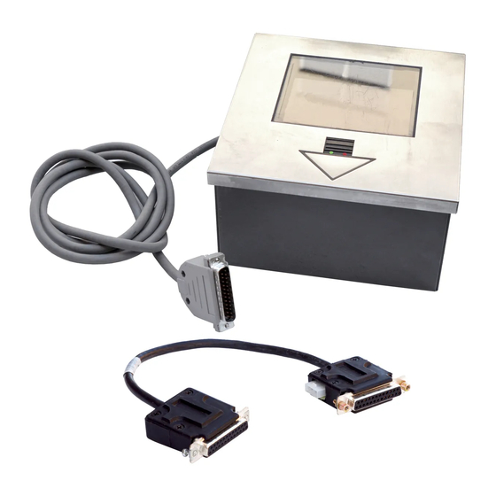
Page 40: Pin Assignments
This can be ordered when the scanner is purchased. The version “1” scanner is designed to be used for RS-232, OCIA or Light Pen Emulation communication. - Page 41 Version “2” Pin Assignments for Parallel Communication The version “2” scanner head cable is terminated with a male 25-pin D-type connector. Connecting the scanner to the host device, may require a communication cable. The communication cable may include a connection for a transformer or it may be designed to draw power directly from the host device.
- Page 42 Version “11” Pin Assignments for RS-485 The version “11” scanner head cable is terminated with a male 25-pin D-type connector. Connecting communication cable. The communication cable may include a connection for a transformer or it may be designed to draw power directly from the host device.
- Page 43 Connecting the communication cable to a PC, may require an adaptor cable. This can be ordered when the scanner is purchased. The version “17” scanner is designed to be used as a keyboard wedge. However, with the appropriate communication cable, the scanner will also provide an RS- 232 or light pen emulation interface.
- Page 44 Version “3” Pin Assignments for Multi-drop RS-422 The version “3” scanner head cable is terminated with a male 25-pin D-type connector. Connecting communication cable. The communication cable may include a connection for a transformer or it may be designed to draw power directly from the host device.
-
Page 45: Pin Assignments
Version “26" Pin Assignments for RS-422 The version “26" scanner head cable is terminated with a male 25-pin D-type connector. Connecting communication cable. The communication cable may include a connection for a transformer or it may be designed to draw power directly from the host device. -
Page 46: Warranty And Disclaimer
INCLUDING, WITHOUT LIMITATION, ANY INJURY TO PROPERTY OR PERSON OR EFFECT ON BUSINESS OR PROFIT, AND IN NO EVENT SHALL ANY LIABILITY OF METROLOGIC EXCEED THE ACTUAL AMOUNT PAID TO METROLOGIC FOR THE PRODUCT. Metrologic Instruments, Inc. 90 Coles Road Blackwood, NJ 08012 Metrologic Instruments GmbH Dornierstrasse 2 82178 Puchheim b. - Page 47 Disclaimer Metrologic Instruments, Inc. and the author or authors make no claims or warranties with respect to the contents or accuracy of this publication, or the product it describes, including any warranties of fitness or merchantability for a particular purpose. Any stated or expressed warranties are in lieu of all obligations or liability for any damages, whether special, indirect, or consequential, arising out of or in connection with the use of this publication or the product it describes.
-
Page 48: Notices
Never attempt to look at the laser beam, even if the scanner appears to be nonfunctional. Never open the scanner in an attempt to look into the device. Doing so could result in hazardous laser light exposure. The use of optical instruments with the laser equipment will increase eye hazard. - Page 49 Manuale può provocare dei raggi laser pericolosi per la vita. Il cliente non deve assolutamente tentare di riparare egli stesso lo scanner laser. Non guardate mai nel raggio laser, anche se credete che lo scanner non sia attivo. Non aprite mai lo scanner per guardare dentro l’apparecchio. Se tuttavia lo fate, potete esporVi a dei raggi laser pericolosi per la vita.
-
Page 50: Patents
Appendix F Patents “Patent Information This METROLOGIC product may be covered by one or more of the following U.S. Patents: U.S. Patent No. 4,360,798; 4,369,361; 4,387,297; 4,460,120; 4,496,831; 4,593,186; 4,607,156; 4,845,350; 4,896,026; 4,923,281; 5,017,765; 5,059,779; 5,140,144; 5,149,950; 5,250,790; 5,250,791; 5,304,788; 5,321,246; 5,324,924; 5,396,053; 5,396,055; 5,408,081; 5,410,139;... -
Page 51: Volume Control Card
Volume Control Card... -
Page 53: Index
Index AC input/outlet 3, 10 Adaptor 7, 10 cable 6, 39 Application Application and protocols 25 Asia Assignments 36-41 Attaching stand Bar codes 1, 4, 5, 9, 13, 14, 16, 20 Beep 3, 4, 10, 16, 19 Beeper operation 27 Base Cable adaptor 6, 39... - Page 54 RS-232 1, 4, 9, 25, 27, 36, 38, 39 RS-422 25, 27, 40, 41 RS-485 25, 38 Scan field(s) Scan lines Scan pattern Scanner connections ScanSet 1, 4, 7, 9, 14-20, 39 ScanSelect manual 7, 9, 14, 15, 20, 28, 39 Scan speed Service 42...
- Page 55 Version identifiers Vertical stand 2, 12 Voltage 3, 10, 27 Volume control card Warranty Watt(s) 26 Weight 26 Window 1, 13, 21, 22, 25-27 47, 48...