
Related Manuals for Metrologic MS2422


Summary of Contents for Metrologic MS2422
- Page 1 METROLOGIC INSTRUMENTS, INC. MS2421 / MS2422 Bar Code Scanner Installation and User’s Guide...
- Page 2 Copyright © 2009 by Metrologic Instruments, Inc. All rights reserved. No part of this work may be reproduced, transmitted, or stored in any form or by any means without prior written consent, except by reviewer, who may quote brief passages in a review, or provided for in the Copyright Act of 1976.
-
Page 3: Table Of Contents
Manual Scope ... 1 Product Overview ... 1 Base Kit Components... 2 Optional Accessories... 2 Replacement Parts... 3 General Precautions... 4 MS2421/MS2422 Scanner Design Specifications ... 5 ODEL HARACTERISTICS MS2421 Scanner... 6 Components ... 6 Dimensions... 7 Connector Panel... 7 Caution and Serial Number Labels... - Page 4 Troubleshooting Symptom / Solution Chart... 39 RS232 Demonstration Program ... 41 EFAULT ETTINGS Communication Parameters ... 42 CANNER AND ABLE ERMINATIONS Scanner Pinout Connections ... 49 Cable Connector Configurations ... 51 EGULATORY OMPLIANCE Safety ... 53 EMC ... 54 ... 56 IMITED ARRANTY ...
-
Page 5: Introduction
COPE This guide provides information on the installation, setup and operation of the MS2421 and the MS2422 scanner only models. If the MS2421 scanner has been integrated with a scale, please refer to the Scale Addendum for detailed instructions on the appropriate cable connections, communication specifications and calibration procedures required by the scale manufacturer and local Weights and Measures Authorities. -
Page 6: Base Kit Components
MS2xxx Stratos Series Configuration Addendum 00-05311 MS2421 / MS2422 Bar Code Scanner Installation and User’s Guide Other items may be ordered for the specific protocol being used. To order additional items, contact the dealer, distributor or call Metrologic’s Customer Service Department at 1-800-ID-METRO or 1-800-436-3876. -
Page 7: Replacement Parts
220V – 240V Australia EPLACEMENT ARTS Part # Window types (Diamonex and Sapphire) are not interchangeable due to laser safety and/or scanner performance differences. Caution To change window type, the scanner must be returned to the manufacturer for reconfiguration. 46-00233 Diamonex Platter –... -
Page 8: General Precautions
NTRODUCTION ENERAL RECAUTIONS The following are some general precautions to remember when handling the MS2421/MS2422 scanner. the unit upside down with the platter in place. on the window in the platter or the RESS vertical window frame. LATTER EMOVAL No hardware or tools are required to remove the platter (see Figure 3). -
Page 9: Ms2421/Ms2422 Scanner Design Specifications
Indicators (LED): Blue flash Mechanical MS2421 L x W x H: 399 mm (15.7") Length MS2422 L x W x H: 353 mm (13.9") Length Depth (Below Counter): 100 mm (3.9"), All Models Weight (with Platter): MS2422, 5.98 kg (13.20 lbs.) -
Page 10: Base Model Characteristics Ms2421 Scanner
DC Power, Scale, and EAS Connectors (see page 7) System Interface Connection Area (see page 7) Optional Leveling Feet (Option provided with scale ready MS2421-105x models only.) Scanner label information can be found on page 8. Figure 5. MS2421 Components ESCRIPTION OF... -
Page 11: Dimensions
ODEL HARACTERISTICS MS2421 Scanner Dimensions Connector Panel Scale ready MS2421 models supply additional connectors for scale and display communication cabling. The use of these connections is dependent on the specific manufacturer of the scale being integrated. Please refer to the custom Scale Installation Guide for detailed instructions on the appropriate cable hookups and calibration procedures for local Weights and Measures authorities. -
Page 12: Caution And Serial Number Labels
Caution and Serial Number Labels Figure 8. MS2421 Label Locations (Top) and Examples (Bottom) Caution: To maintain compliance with applicable standards, all circuits connected to the scanner must meet the requirements for SELV (Safety Extra Low Voltage) according to EN/IEC 60950-1. -
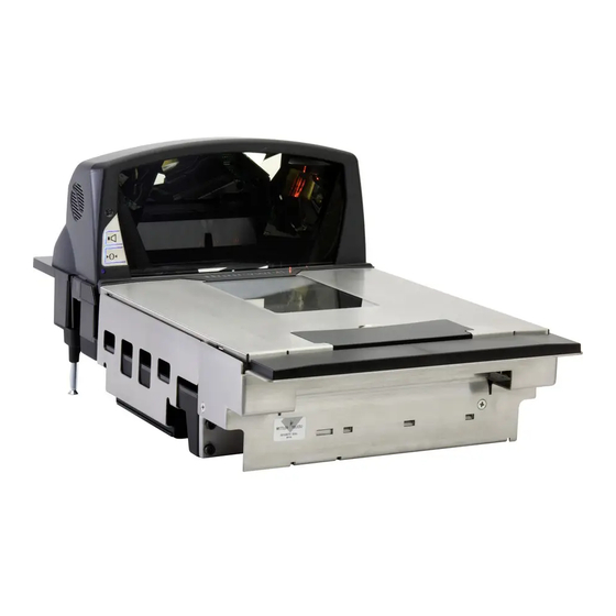
Page 13: Ms2422 Scanner
Diagnostic Indicator Display (see page 31) DC Power, Scale, and EAS Connectors (see page 10) System Interface Connection Area (see page 10) Scanner label information can be found on page 11. Figure 9. MS2422 Components ESCRIPTION OF TEM IN IGURE... -
Page 14: Dimensions
ODEL HARACTERISTICS MS2422 Scanner Dimensions Figure 10. MS2422 Dimensions Connector Panel Figure 11. MS2422 Connectors Specifications are subject to change without notice. -
Page 15: Caution And Serial Number Labels
Caution and Serial Number Labels Figure 12. MS2422 Label Locations (Top) and Examples (Bottom) Caution: To maintain compliance with applicable standards, all circuits connected to the scanner must meet the requirements for SELV (Safety Extra Low Voltage) according to EN/IEC 60950-1. -
Page 16: Installation
• The MS2421/MS2422 can scan a bar code on five sides of a package. The packages should flow into the scan area that provides the maximum reading performance. No lifting or orientation of the items is necessary. A properly placed item diverter can maximize the flow of packages. -
Page 17: Unpacking The Unit
• Power Supply • Communication Cables Lift the scanner out of the shipping box by gripping the bottom of the unit on both sides. Important! Do not lift the unit out of the box by gripping the sides of the platter. -
Page 18: Ms2421 Mounting Diagram
NSTALLATION NSTALLING THE NIT IN THE OUNTER MS2421 Mounting Diagram Figure 17. MS2421 Mounting Diagram Specifications are subject to change without notice. -
Page 19: Ms2422 Mounting Diagram
NSTALLATION NSTALLING THE NIT IN THE OUNTER MS2422 Mounting Diagram Figure 18. MS2422 Mounting Diagram Specifications are subject to change without notice. -
Page 20: Cable Installation (Interface Specific)
Plug the 10-pin RJ45 end of the RS232 interface cable ( into the 10-pin socket labeled Scanner Host RS232, on the bottom of the scanner. Refer to figure on page 17. Connect the other end of the RS232 cable to the proper communication port on the host device. - Page 21 NSTALLATION ABLE NSTALLATION NTERFACE RS232 xx** Specifies international connection. See the Base Kit Components and Optional Accessories section of this guide for a complete listing. See power source caution statement on pages 8 or 11 of this manual. PECIFIC Figure 19. RS232 Interface Cable Installation Schematic...
-
Page 22: Full Speed Usb
Dual Cable Scanner Configuration Bar Codes, IBM OEM Full Speed USB Communication Defaults and IBM OEM Full Speed USB Protocols. Applies only with MS2421 non-scale scanner models. If a scale has been integrated into a scale ready MS2421, the configuration bar code shown does not apply. -
Page 23: Usb Serial Emulation Mode
Step 8 is for USB Serial Emulation Mode or Keyboard Emulation Mode only. Configure the scanner for USB Serial Emulation Mode or USB Keyboard Emulation Mode by scanning the appropriate configuration bar codes in the USB section of the MetroSelect Configuration Guide ( under Low Speed USB. -
Page 24: Ibm 46Xx
IBM 46 The following steps describe how to properly install the cables for an IBM 46xx scanner application. The scanner must then be configured to match the host’s IBM 46xx parameters. Cable installation alone does not guarantee that the scanner will communicate properly with the host system. - Page 25 NSTALLATION ABLE NSTALLATION NTERFACE IBM 46 xx** Specifies international connection. See the Base Kit Components and Optional Accessories section of this guide for a complete listing. See power source caution statement on pages 8 or 11 of this manual. PECIFIC Figure 21.
-
Page 26: Cable Installation (Secondary Metrologic Scanner)
Connect the angled end of the RS232 AUX cable ( the bottom of the MS2421/MS2422 scanner. Important: The MS2421/MS2422 series’ aux port requires the signals; transmit, receive, RTS & CTS from the secondary scanner. MS2421/MS2422 scanner auxiliary port will support 5VDC devices with a 150mA maximum current. If the auxiliary device exceeds this specification an external power supply will be required to power the auxiliary device. - Page 27 NSTALLATION ABLE NSTALLATION ECONDARY † See Aux power notes on page 22 See power source caution statement on pages 8 or 11 of this manual. ETROLOGIC CANNER Figure 22. Secondary Scanner Cable Installation Schematic...
-
Page 28: Eas Deactivation
Base Model MS2421 MS2422 All MS2421/MS2422 models have a connector labeled EAS In on the bottom of the unit. Metrologic has an optional EAS cable 52-52511x) available for purchase for connection between the Checkpoint device and the MS2421/MS2422 scanner. MLPN Figure 23. -
Page 29: Scanner Operation Scan Zone
CANNER PERATION Figure 25. Checker-Side (13 mil) Figure 26. Horizontal Left/Right (13 mil) Specifications are subject to change without notice. - Page 30 CANNER PERATION Figure 27. Horizontal Direct (13 mil) Figure 28. Vertical Direct (13 mil) Specifications are subject to change without notice.
-
Page 31: Wake Activation Area (Photocell Led Output)
OFF after a configured period of non-use then turns the motor OFF after thirty-minute intervals. Any movement detected by the photocell in the activation area, shown below in grey, will cause the scanner to exit the power save mode. -
Page 32: Changing The Wake Area Sensitivity Level
ENSITIVITY Changing the Wake Area Sensitivity Level (Photocell LED Range Adjust) The MS2400 Series bar code scanner wake area sensitivity level can be set to the end users preference by scanning one of the Photocell Sensitivity adjustment bar codes below. -
Page 33: Indicator Descriptions
Audible When in operation, the MS2421/MS2422 scanner provides audible feedback that indicates the status of the unit and the current scan. Eight settings are available for the tone of the beep (normal, 6 alternate tones and no tone) plus three volume settings. -
Page 34: Failure
Steady Blue and Single blue Flash When the scanner successfully reads a bar code, the blue LED will flash and the scanner will beep once. If the blue LED does not flash or the scanner does not beep once, then the bar code has not been successfully read. -
Page 35: Diagnostic Indicator Display; Error Codes
“break” signal constantly and continuous attempts are made to enter MetroSet configuration mode. A short on the RX Data line can cause this condition. It can also be the result of a laptop in power save mode. The scanner will abort attempts to enter configuration mode after a short timeout. - Page 36 LASER #2 (RIGHT HORIZONTAL) ERROR – The right laser in the horizontal scanning subsystem denotes a failure. The scanner will try three times to correct the laser operation. If the laser error persists, and the left horizontal laser (#3) is also in error, the horizontal scanning subsystem will be shut down and this error code will remain on the Diagnostic Indicators.
- Page 37 MOTOR #2 (HORIZONTAL) ERROR – The motor in the horizontal scanning subsystem denotes a failure. The scanner will try three times to correct the motor operation. If the motor error persists, the horizontal scanning subsystem will be shut down and this error code will remain on the Diagnostic Indicators.
-
Page 38: Power Save Modes
PERATION OWER ODES The MS2421/MS2422 bar code scanners have five configurable power save modes. Refer to the MetroSelect Configuration Guide for additional information on Power Save Modes. Blink Power Save Mode: Blinks the laser OFF & ON after a configured period of non-use. -
Page 39: Beeper Options And Button Functions
This feature is configuration dependent. Refer to the MetroSelect Configuration Guide 00-02407x) under Scanner Operation: Power Save Modes to enable this feature. MLPN Waking the Unit from All Power Save Modes The next button depression will awaken the scanner for normal operation. -
Page 40: Startup
CANNER PERATION TARTUP When the scanner first receives power, the blue LED will turn on and the scanner will beep once. The scanner is now ready to scan. OWER When a MS2421/MS2422 scanner is first powered up, it cycles through a number of self-tests before starting normal operation. -
Page 41: Maintenance
* See replacement parts on page 3. † If the platter on the MS2421 is not equipped with a product weight roll bar / lift handle, it can be removed using the same method as shown for the MS2422. EPLACEMENT... -
Page 42: Daily Maintenance
Smudges and dirt can interfere with the proper scanning of a bar code. Therefore, the horizontal and vertical output windows will need occasional cleaning. For the vertical and horizontal (platter) glass windows: Spray glass cleaner onto lint free, non-abrasive cleaning cloth. Gently wipe the scanner windows until clean. -
Page 43: Troubleshooting
XON/XOFF or D/E, verify that the host cable and host are supporting the handshaking properly. Verify that the scanner’s data format matches that required by the host. Make sure that the scanner is connected to the proper host port. Solution... - Page 44 Check if check digits are set properly. Check if the correct minimum symbol length is set. Check to make sure that the baud rate and parity of the scanner and the communication port match and the program is looking for RS232 data. Solution...
-
Page 45: Rs232 Demonstration Program
This program is for demonstration purposes only. It is only intended to prove that cabling is correct, the com port is working, and the scanner is working. If the bar code data displays on the screen while using this program, it only demonstrates that the hardware interface and scanner are working. -
Page 46: Default Settings
Many functions of the scanner can be "configured" - that is, enabled or disabled. The scanner is shipped from the factory pre- configured to a set of default conditions. The default parameter of the scanner has an asterisk ( * ) in the charts on the following pages. - Page 47 EFAULT ETTINGS OMMUNICATION ARAMETERS ARAMETER RSS Expanded Enable Expanded ID “]e0” RSS Limited Enable RSS Limited ID “]e0” RSS Limited App ID “01” RSS Limited Check Digit DTS/SIEMENS DTS/NIXDORF NCR F NCR S Beeper Tone Beep Transmit Sequence Beeper Volume Power-Up Disable Good Scan Beep Communication Timeout Razzberry Tone on Timeout...
- Page 48 EFAULT ETTINGS OMMUNICATION ARAMETERS ARAMETER Dual Action Power Save Mode #2 Same Symbol Rescan Timeout: 500 msecs Configurable in 50 msec steps (MAX 6.35 seconds) Intercharacter Delay Configurable in 1 msec steps (MAX 255 msecs) Number of Scan Buffers UPC GTIN-14 Format EAN-8 Enable Transmit EAN-8 Check Digit Convert EAN-8 to EAN-13...
- Page 49 Activate on DC2 Character Xmit No Read Message on DC2 Timeout No Transmit LED During No Read Message Configurable “No Read” Message Recv “I” = Transmit “METROLOGIC” Recv “i” = Transmit Scanner ID Byte RS232 EFAULT Space 9600 IBM 46...
- Page 50 EFAULT ETTINGS OMMUNICATION ARAMETERS ARAMETER STX Prefix TAB Prefix Metrologic Prefix UPC Prefix ETX Suffix TAB Suffix Carriage Return Suffix Line Feed Suffix UPC Suffix Transmit LRC Start LRC on 1 Byte Start LRC on 2 Byte ‘c’ Prefix for UPC ‘$’...
- Page 51 EFAULT ETTINGS OMMUNICATION ARAMETERS ARAMETER Five Digit Redundancy Enable Coupon Code 128 Transmit Coupon ‘]C1’ Group Separator Coupon Code Can Begin with ’4’ Enable EAN-99 Coupon Code Bookland Supplements French 378/379 Supplements German 434/439 Supplements Convert Bookland to ISBN Bookland 979 Supplements Convert 979 to ISBN Convert 290 to ISBN Reformat ISBN...
- Page 52 EFAULT ETTINGS OMMUNICATION ARAMETERS Default settings for “Aux” interface The secondary scanner and the MS2421/MS2422 scanner always communicates via RS232. Data is relayed to the host via various primary interfaces ARAMETER Aux Baud Rate Aux Parity Aux Data Bits Aux Stop Bits...
-
Page 53: Scanner And Cable Terminations
CANNER AND ABLE ERMINATIONS CANNER INOUT ONNECTIONS The MS2421/MS2422 scanner terminates to 10-pin modular jacks located on the bottom of the unit. The serial number label indicates the model number and interface of the scanner. DC Power Function Function EAS In... - Page 54 EADY ODELS There are four additional 10-pin modular jacks located on the bottom of the of the MS2421 scanner models that may be used for an integrated scale application and the use of a remote display. Please keep in mind that every application is unique. The use of these connections depends on the specifications of the scale’s manufacturer.
-
Page 55: Cable Connector Configurations
ONFIGURATIONS The following cables are examples of some of the standard cables that may be shipped with the MS2421/MS2422 bar code scanner. Please keep in mind that every application is unique and the cables received with the MS2421/MS2422 scanner may be custom cables that are not shown below. - Page 56 +5VDC – Transformer / Direct Shield Ground * This configuration cable was designed to be used with the MS2421/MS2422 auxiliary connector only. ** All signals are referenced from the MS2421/MS2422 scanner. † All signals are referenced from the auxiliary / secondary scanner.
-
Page 57: Regulatory Compliance Safety
Under no circumstances should the customer attempt to service the laser scanner. Never attempt to look at the laser beam, even if the scanner appears to be nonfunctional. Never open the scanner in an attempt to look into the device. -
Page 58: Emc
Class A Devices The following is applicable when the scanner cable is greater in length than 3 meters (9.8 feet) when fully extended: Les instructions ci-dessous s’appliquent aux cables de scanner dépassant 3 métres (9.8 pieds) de long en extension maximale: Folgendes trifft zu, wenn das Scannerkabel länger als 3 Meter ist:... - Page 59 Class B Devices The following is applicable when the scanner cable is less than 3 meters (9.8 feet) in length when fully extended: Les instructions ci-dessous s’appliquent aux cables de scanner ne dépassant pas 3 métres (9.8 pieds) de long en extension maximale: Folgendes trifft zu, wenn das Scannerkabel kürzer als 3 Meter ist:...
-
Page 60: Limited Warranty
THE PRODUCT, EXCEPT AS STATED IN THIS WARRANTY. IN NO EVENT SHALL ANY LIABILITY OF METROLOGIC EXCEED THE ACTUAL AMOUNT PAID TO METROLOGIC FOR THE PRODUCT. METROLOGIC RESERVES THE RIGHT TO MAKE ANY CHANGES TO THE PRODUCT DESCRIBED HEREIN. ORLDWIDE EADQUARTERS Metrologic Instruments, Inc. 90 Coles Rd. Blackwood, NJ 08012-4683 Tel: 856-228-8100 Fax: 856-228-6673 Email: info@metrologic.com... -
Page 61: Patents
ATENTS Patent Information This METROLOGIC product may be covered by, but not limited to, one or more of the following U.S. Patents: U.S. Patent No.; 5,343,027; 5,627,359; 5,686,717; 5,789,731; 5,828,049; 6,029,894; 6,209,789; 6,299,065; 6,345,505; 6,422,467; 6,481,625; 6,494,377; 6,814,292; 6,830,190; 6,874,690; 6,918,540; 6,951,304; No license right or sublicense is granted, either expressly or by implication, estoppel, or otherwise, under any METROLOGIC or third party intellectual property rights (whether or not such third party rights are licensed to METROLOGIC), including any third party patent listed above, except for an implied license only for the normal intended use of the specific equipment,... -
Page 62: Index
NDEX AC ... see power application ...31, 41 audible...see indicators AUX...6, 41, 49 beep ...see indicators blue LED ...see indicators button multi-function ...6, 9, 35 tone ...6, 9, 35 volume...6, 9, 35 cable...12, 39, 40, 41 communication ...2, 13, 16–21 EAS ...2, 24 pinouts...49–52 power...2... -
Page 63: Scan Zone
NDEX safety...54, 55 Scale ...50 scan pattern ...5 scan speed...5 scan zone...25–26 scanner pinouts...49–52 secondary scanner ...22, 23 SELV ...16–21 specifications...5 storage ...5 switch ...24 test ...36 tone ...6, 9, 29, 35 transformer... see power troubleshooting...39–41 USB...42–48 ventilation ...5, 12 visual...30... - Page 66 January 2009, Version 04 0 0 - 0 5 3 1 1 A...