Sony RDR-VX521 Service Manual
Hide thumbs
Also See for RDR-VX521:
- Operating instructions manual (132 pages) ,
- Quick start manual (2 pages) ,
- Limited warranty (1 page)
Table of Contents
Advertisement
Quick Links
SERVICE MANUAL
System
[DVD recorder section]
Laser
Semiconductor laser
Audio recording format
Dolby Digital
Video recording format
MPEG Video
[VCR section]
Format
VHS NTSC standard
Video recording system
Rotary head helical scanning FM system
Video heads
Double azimuth four heads
Video signal
NTSC color, EIA standards
Tape speed
3
SP: 33.35 mm/s (1
/
inches/s)
8
7
EP: 11.12 mm/s (
/
inches/s)
16
11
LP: 16.67 mm/s (
/
inches/s),
16
playback only
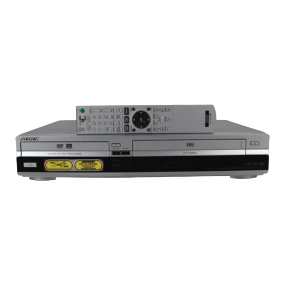
RDR-VX521/VX530
Photo: RDR-VX530
SPECIFICATIONS
Maximum recording/playback time
8 hrs. in EP mode (with T-160 tape)
Rewind time
Approx. 1 min (with T-120 tape)
[Tuner section]
Channel coverage
VHF 2 to 13
UHF 14 to 69
CATV A-8 to A-1, A to W, W+1 to W+84
Antenna
75-ohm antenna terminal for VHF/UHF
[Timer section]
Clock
Quartz locked
Timer indication
12-hour cycle
Timer setting
12 programs in total (max.)
Canadian Model
Mexican Model
Refer to the SERVICE MANUAL of VHS MECHANI-
CAL ADJUSTMENT MANUAL VII for MECHANICAL
ADJUSTMENTS. (9-921-790-11)
Inputs and outputs
LINE 1 IN and LINE 2 IN
VIDEO IN, phono jack (1 each)
Input signal: 1 Vp-p, 75 ohms, unbalanced,
sync negative
AUDIO IN, phono jacks (2 each)
Input level: 327 mVrms
Input impedance: more than 47 kilohms
LINE 2 IN
S VIDEO, 4-pin, mini-DIN jack
Y: 1.0 Vp-p, unbalanced, sync negative
C: 0.286 Vp-p, load impedance 75 ohms
DV IN, 4-pin jack, i.LINK S100
LINE OUT
VIDEO OUT, phono jack (1)
Output signal: 1 Vp-p, 75 ohms,
unbalanced, sync negative
AUDIO OUT, phono jacks (2)
Standard output: 327 mVrms
Load impedance: 47 kilohms
Output impedance: less than 10 kilohms
VIDEO CASSETTE RECORDER/
DVD RECORDER
RMT-D224A
US Model
RDR-VX521/VX530
RDR-VX530
DX-13A MECHANISM
— Continued on next page —
Advertisement
Table of Contents

Related Manuals for Sony RDR-VX521


Summary of Contents for Sony RDR-VX521
- Page 1 RDR-VX521/VX530 RMT-D224A SERVICE MANUAL US Model RDR-VX521/VX530 Canadian Model Mexican Model RDR-VX530 DX-13A MECHANISM Photo: RDR-VX530 Refer to the SERVICE MANUAL of VHS MECHANI- CAL ADJUSTMENT MANUAL VII for MECHANICAL ADJUSTMENTS. (9-921-790-11) SPECIFICATIONS System Maximum recording/playback time Inputs and outputs 8 hrs.
- Page 2 DIGITAL AUDIO OUT General Dimensions including projecting parts OPTICAL, Optical output jack and controls (w/h/d) Power requirements −18 dBm (wave length: 660 nm) Approx. 430 × 82 × 334 mm 120 V AC, 60 Hz (Approx. 17 × 3 × 13 COAXIAL, phono jack Power consumption inches)
- Page 3 SONY PARTS WHOSE PART NUMBERS APPEAR AS DE FONCTIONNEMENT. NE REMPLACER CES COM- SHOWN IN THIS MANUAL OR IN SUPPLEMENTS POSANTS QUE PAR DES PIÈCES SONY DONT LES PUBLISHED BY SONY. NUMÉROS SONT DONNÉS DANS CE MANUEL OU DANS LES SUPPLÉMENTS PUBLIÉS PAR SONY.
-
Page 4: Table Of Contents
TABLE OF CONTENTS Precautions Block Diagram ............3-1 Safety Precautions ······························································ 5 Servicing Precautions ························································ 7 PCB Diagrams ESD Precautions ································································· 8 VCR Main PCB ······························································· 4-3 Handling the Optical Pick-up ············································· 9 DVD Jack Main PCB ······················································ 4-7 Reset operation after IC203 was replaced ························ 10 DV Jack PCB ·································································... -
Page 5: Safety Precautions
PRECAUTIONS 1 SAFETY PRECAUTIONS 1) Before returning an instrument to the customer, always make a (4) Insulation Resistance Test Cold Check-(1) Unplug the power safety check of the entire instrument, including, but not limited supply cord and connect a jumper wire between the two prongs to, the following items: of the plug. - Page 6 6) Product Safety Notice-Some electrical and mechanical parts have special safety-related characteristics which are often not evident from visual inspection, nor can the protection they give necessarily be obtained by replacing them with components rated for higher voltage, wattage, etc. Parts that have special safety characteristics are identified by shading, an ( ) or a ( ) on...
-
Page 7: Servicing Precautions
2 SERVICING PRECAUTIONS CAUTION: Before servicing units covered by this service manual 2-2 Insulation Checking Procedure and its supplements, read and follow the Safety Precautions section of this manual. Disconnect the attachment plug from the AC outlet and turn the power ON. -
Page 8: Esd Precautions
3 ESD PRECAUTIONS Electrostatically Sensitive Devices (ESD) Some semiconductor (solid state) devices can be damaged easily by static electricity. Such components commonly are called Electrostatically Sensitive Devices (ESD). Examples of typical ESD devices are integrated circuits and some field-effect transistors and semiconductor chip components. -
Page 9: Handling The Optical Pick-Up
4 HANDLING THE OPTICAL PICK-UP The laser diode in the optical pick up may suffer electrostatic breakdown because of potential static electricity from clothing and your body. The following method is recommended. (1) Place a conductive sheet on the work bench (The black sheet used for wrapping repair parts.) (2) Place the set on the conductive sheet so that the chassis is grounded to the sheet. -
Page 10: Reset Operation After Ic203 Was Replaced
5 Reset operation after IC203 was replaced Be sure to perform the reset by the method described below, if the IC203 (FLASH MEMORY) used on the DVD Jack Main board was replaced. Resetting method 1. Enter the Adjustment mode, and press two times the “1” button on the remote commander. -
Page 11: General
RDR-VX521/VX530 1. GENERAL This section is extracted from RDR-VX530 instruc- tion manual. (2-672-429-11) About this manual What is a Video Cassette Recorder/DVD Recorder? • Instructions in this manual describe the controls on the remote. You can also use the controls on the recorder if... -
Page 12: Hookups And Settings
Selectable options Sub-menu Using the cable box/satellite Selectable options on the System Menu differ Hookups and Settings receiver control function depending on the media type, disc condition, and The sub-menu appears when you select an item operating status. from a list menu (e.g., a title from the Title List The cable box/satellite receiver control function Hooking Up the Recorder menu), and press ENTER. - Page 13 C: Cable without cable box, or antenna only (no cable TV) Step 3: Connecting to Your TV Use this hookup if you watch cable channels without a cable box. Also use this hookup if you are using a VHF/UHF antenna or separate VHF and UHF antennas. Connect the supplied audio/video cord to the LINE OUT (VIDEO/AUDIO L/R) jacks of the recorder.
- Page 14 AUDIO. to AC outlet Surround 3 Notes • If the supplied remote interferes your other Sony DVD recorder or player, change the command mode number for this recorder (page 26). • Use the batteries correctly to avoid possible leakage and corrosion.
- Page 15 Press CH +/– and check that the channel mode number for this recorder and the supplied Options 10:10 AM No Disc changes on the cable box/satellite receiver remote to one that differs from the other Sony Title List Language DVD recorder or player. window. Parental...
-
Page 16: Quick Guide To Disc Types
Select “Command Mode,” and press Connecting Another VCR or Similar Device ENTER. No Disc Options 10:10 AM After disconnecting the recorder’s power cord from an AC outlet, connect the other VCR or similar Title List Language recording device to the LINE IN jacks of this recorder. See also the instruction manual supplied with the Parental Timer connected equipment. -
Page 17: Playable Discs
12 cm/8 cm discs 12 cm 8 cm Disc Type Playback Recording Playback Recording Recording Features Editing Features DVD+RW Change Erase VR mode Auto Manual Divide Rewrite Title Title/ Playlist DVD-RW Chapter Chapter Erase Title (page 70) Name Chapter (page 64) (page 51) (page 62) (page 60) -
Page 18: Dvd Playback
To stop playback Press x STOP. Playback Options DVD Playback z Hints Playing • You can play DATA CDs or DATA DVDs with MP3 Z OPEN/CLOSE audio tracks or JPEG image files (pages 43 or 44). • If you insert a DVD VIDEO, VIDEO CD, or CD, - RW - RW Video... - Page 19 – you edit the title after stopping playback. Playing quickly with sound (Scan Locking the recorder (Child Lock) Playing a Title From the – you make a recording. Audio) (DVDs with Dolby Digital soundtracks You can lock all of the buttons on the recorder so Title List Repeating a specific portion only)
-
Page 20: Playing Mp3 Audio Tracks
To switch between MP3 audio tracks and JPEG To display the previous or next image, press ./>. Playing MP3 Audio Tracks image files 10:10 AM Press x STOP, and press TOP MENU. Music and JPEG Image Files The following menu icons appear in the upper Press ENTER : Photo z Hint... -
Page 21: Dvd Recording
D Remaining disc space (in stop mode) Recording mode and recording time Remaining time of the current title (during The following table is an approximate guide for DVD Recording the recording time on a single DVD (4.7 GB). playback E Channel or input source Recording mode Approximate Before Recording... -
Page 22: Dvd Timer Recording
Press Z OPEN/CLOSE to close the disc Press ENTER. DVD Timer Recording tray. The Timer List menu (page 55) appears. The c indicator lights up in the front panel Wait until “LOAD” disappears from the front Record 0:00:03 display, and the recorder is ready to start panel display. -
Page 23: Dvd Editing
Select the timer setting you want to change • You cannot change the timer settings for a recording Changing or Canceling DVD Recording From Connected currently underway. or cancel, and press ENTER. • The Timer List displays both the DVD recorder and The sub-menu appears. - Page 24 Select an option, and press ENTER. Press TITLE LIST. In this case, you can compile highlight scenes as a Editing a Title Playlist title. You can even rearrange the scene You can select from the following: Press ORIGINAL/PLAYLIST to switch to the order within the Playlist title.
- Page 25 Select the character you want to enter Notes Changing the Name of a Creating a Playlist using M/m/</,, and press ENTER. • If a message appears and indicates that no more chapter The selected character appears in the input Title marks can be added, you may not be able to record or row.
- Page 26 Select a Playlist title to be combined. Follow steps 1 to 7 of “Editing a Playlist” “Move”: Allows you to change scene order Moving a scene (Move) (page 68). (page 66). “Add”: Allows you to add other scenes before The “Edit Scene” display appears. Playlist 10:10 AM - RW...
-
Page 27: Vcr Playback
To return to the previous display To stop playback Press O RETURN. Press x STOP. VCR Playback z Hints To eject the tape • You can set protection for individual titles (page 59). Playing Press Z OPEN/CLOSE. • By reformatting, you can change the recording format on DVD-RWs, or record again on DVD-RWs (Video To turn off the power while rewinding (Rewind mode) that have been finalized. -
Page 28: Vcr Recording
Viewing information on the front Searching Using Various Displaying the Playing Time panel display Functions and Play Information You can view the information on the front panel Go to Zero display. 0:00:00 The VCR automatically marks the tape with an You can check playback information, such as Press TIME/TEXT repeatedly. -
Page 29: Vcr Timer Recording
To stop recording When the counter reaches “0:00,” the recorder Notes VCR Recording Without the Press x STOP. stops recording and turns off. • The remaining tape length may not be indicated Timer accurately for short tapes such as T-20 or T-30, or tapes To pause recording recorded in LP mode. - Page 30 Select “to VIDEO,” and press ENTER. Notes Recording From Connected Changing or Canceling VCR Press SYSTEM MENU to turn off the menu. • The recorder starts recording only after detecting the Equipment With a Timer Timer Settings (Timer List) video signal from the connected equipment. The Set the timer on the connected equipment beginning of the program may not be recorded (Synchro Rec)
-
Page 31: Dubbing (Tapa Y Dvd)
Press DVD and insert a recordable disc. Select “Yes,” and press ENTER. Dubbing From a DVD to a Dubbing starts. To select the recording mode, press REC Dubbing (TAPE DVD) MODE repeatedly (see page 48). VHS Tape Insert a source VHS tape. z Hints Dubbing From a VHS Tape to •... -
Page 32: Dv/D8 Dubbing (Dv/D8 T Dvd)
To stop dubbing Press x STOP. Finalizing a Disc (Preparing Note that it may take a few seconds for the a Disc for Playback on Disc will be finalized. recorder to stop dubbing. Do you want to continue ? Other Equipment) z Hints Cancel •... -
Page 33: Settings And Adjustments
Select “DV/D8 Audio Input,” and press Follow steps 1 to 11 of “Dubbing From a Dubbing an entire DV/D8 format tape ENTER. DV/D8 Format Tape to a DVD” (page 94), DV Tape Mode to a DVD (One Touch Dubbing) and press SYSTEM MENU to turn off the Audio 10:10 AM display. - Page 34 Select an option, and press ENTER. automatically search for a channel that carries Clock Setting (Clock Set) Video Settings (Video) a time signal. Select “Auto Preset,” and press ENTER. All receivable channels are preset in Clock Set CH 10:10 AM numerical sequence.
- Page 35 Downmix (DVDs only) Scan Audio (DVDs only) Digital Out 10:10 AM Recording, Set Top Box Switches the method for mixing down to two Title List Dolby Digital : 4:3 Letter Box D-PCM Outputs audio signals during channels when you play a DVD which has rear Control, and VCR Settings Dolby Digital FF1 fast-forward of a DVD...
-
Page 36: Additional Information
Select this to run the Easy Setup program. After step 3 above, select “Parental,” and Change Password Level 8 (Adults) Timer Sony DVD player or more than one Sony DVD press ENTER. Level 7 recorder” on page 26. Edit • If you have not entered a password, the... - Page 37 Other characters are displayed as , The recorder’s internal clock stopped due to a , The DVD VIDEO prohibits changing of the the video heads using a Sony video head cleaning asterisks. power failure. The clock is automatically set by cassette.
-
Page 38: Guide To Parts And Controls
The maximum baud rate of equipment on which it If a Sony cleaning cassette is not available in your connected by a single i.LINK cable. Possible is not indicated such as this unit is “S100.”... - Page 39 V ?/1 (on/standby) button (23) A TV/DVD·VIDEO switch (21) For VCR functions W CH (channel) +/– buttons* (21, 49) B Z OPEN/CLOSE (eject) button (72) X VOL (volume) +/– buttons (21) C Number buttons* (21) SET button (21) Y TV/VIDEO button (21) D CLEAR button (72) Z INPUT SELECT button (49, 56, 94) E AUDIO button* (77)
- Page 40 0440 0069, 0649, 0255, 0305, Funai 0248, 0019 0032, 0111, 0317 Skygiant 1091 Macom 0033 FutureVision 0649 Pioneer 0144, 0023, 0533, 1877, SL Marx 0040 Maestro 0812 Garrard 0153 0877, 0260 Sony 1006 Gateway 0764 Popular Mechanics 0400 ,continued 1-30...
- Page 41 0274 US Electronics 0276, 0008, 0003, 0017 Dish Network System 0775, 1005, 1170 0856, 0099, 1856 Stellar One 0807 0883 Dishpro 0775, 1005 Sony 0639, 1639 Storm 1018, 0637 Verizon 0246 Echostar 0775, 1170, 1005 Star Choice 0869 Suena Madritel...
- Page 42 “TV Type” 100 TV/DVD·VIDEO 21 TV/VIDEO 50 “Unfinalize” 92 Unrecordable pictures 49 “VCR Function” 105 VIDEO CD 33 Video mode 30 Video settings 100 VR mode 30 ZOOM 36 Zoom 44 Sony Corporation Printed in China AK68-00986A 1-32E...
-
Page 43: Disassembly And Reassembly
RDR-VX521/VX530 2. DISASSEMBLY AND REASSEMBLY 2-1 CABINET AND PCB 2-1-1 Cabinet Top Removal 2-1-3 Ass’y Front Panel Removal 1 REMOVE 1 SCREW 3 Lift up the Cabinet Top in the direction of arrow 1 REMOVE 2 REMOVE 1 SCREW 3 SCREWS... -
Page 44: Chassis Removal
2-1-5 Chassis Removal 2 REMOVE 4 SCREWS 3 REMOVE 4 SCREWS VCR DECK 1 REMOVE 2 SCREWS DVD DECK 5 REMOVE 5 SCREWS VCR MAIN PCB 4 REMOVE 6 SCREWS DVD JACK MAIN PCB FRONT JACK PCB DV JACK PCB FUNCTION TIMER PCB Fig. -
Page 45: Circuit Board Locations
2-2 CIRCUIT BOARD LOCATIONS DVD JACK MAIN PCB VCR MAIN PCB FRONT JACK PCB FUNCTION TIMER PCB Fig. 2-7 Circuit Board Locations... -
Page 46: Vcr Deck Parts Locations
2-3 VCR DECK PARTS LOCATIONS 2-3-1 Top View Fig. 2-8 Top parts Location-1 1 GEAR FL CAM 2 ASS’Y MOTOR LOADING 3 ASS’Y LEVER ARM 4 ASS’Y HOLDER CASSETTE 5 LEVER FL DOOR 6 SLIDER FL DRIVE... - Page 47 qa 0 qs Fig. 2-9 Top Parts Location-2 1 FE HEAD 8 DISK S REEL 2 ASS’Y CYLINDER 9 ASS’Y LEVER S BRAKE 3 ASS’Y ACE HEAD 0 GEAR IDLE 4 ASS’Y LEVER UNIT PINCH qa LEVER IDLE 5 ASS’Y LEVER #9 GUIDE qs ASS’Y LEVER T BRAKE 6 ASS’Y LEVER TENSION qd DISK T REEL...
-
Page 48: Bottom View
2-3-2 Bottom View Fig. 2-10 Bottom Parts Location 1 GEAR JOINT 1 2 GEAR JOINT 2 3 BRAKET GEAR 4 ASS’Y MOTOR CAPSTAN 5 ASS’Y LEVER T LOAD 6 GEAR LOADING DRIVE 7 ASS’Y LEVER S LOAD 8 ASS’Y CLUTCH 9 BELT PULLEY 0 SLIDER CAM... -
Page 49: Vcr Deck
2-4 VCR DECK 2-4-1 Ass’y Holder Cassette Removal 2-4-2 Ass’y Lever Arm Removal 1) Pull the Ass’y Holder Cassette 1 to the eject position. 1) Push the hole “A” in the direction of arrow “B” use the pin.(about 2) Pull the Ass’y Holder Cassette 1 as grasping the Ass’y Holder Dia. -
Page 50: Lever Fl Door Removal
2-4-3 Lever Door Removal 2-4-4 Slider FL Drive, Gear FL Cam Removal 1) Release the Hook 2 and Remove the Lever Door 1 in the 1) Pull the Slider FL Drive 1 to the front direction. direction of arrow “A”. 2) Remove the Slider FL Drive 1 in the direction of arrow. -
Page 51: Gear Worm Wheel Removal
2-4-5 Gear Worm Wheel Removal 2-4-6 Cable Flat Removal 1) Remove the Gear Worm wheel 1. 1) Remove the Drum connecting part of Cable Flat 1 from Connector Waffer 2, 3. 1 CABLE FLA T 2 CONNECTOR W AFER 3 CONNECTOR W AFER 1 GEAR WORM WHEEL Fig. -
Page 52: Ass'y Motor Loading Removal
2-4-7 Ass’y Motor Loading Removal 2-4-8 Bracket Gear, Gear Joint 2, 1 Removal 1) Remove the Screw 1. 1) Remove the Screw 1. 2) Remove the Ass’y Motor Loading 2. 2) Remove the Bracket Gear 2. 3) Remove the Gear Joint 2 3. 4) Remove the Gear Joint 1 4. -
Page 53: Gear Loading Drive, Slider Cam
2-4-9 Gear Loading Drive, Slider Cam, 2-4-10 Gear Loading Drive, Slider Cam, Ass’y Lever Load S, T Removal Ass’y Lever Load S, T Assembly 1) Remove the Belt Pulley. (Refer to Fig. 2-38) 1) When reinstalling, be sure to align dot of Ass’y Lever Load T 2) Remove the Gear Loading Drive 1 after releasing Hook [A] in 1 with dot of Ass’y Lever Load S 2 as shown in drawing, the direction arrow as shown in detail drawing. -
Page 54: Lever Pinch Drive, Lever Tension Drive Removal
2-4-11 Lever Pinch Drive, 2-4-12 Ass’y Lever Tension, Lever Tension Drive Removal Ass’y Band Brake Removal 1) Remove the Lever Pinch Drive 1, Lever Tension Drive 2. 1) Remove the Ass’y Lever Brake S (Refer to Fig 2-25). 2) Remove the Spring Tension Lever 1. 1 LEVER PINCH DRIVE 3) Rotate stopper of Main Base in the direction of arrow “A”. -
Page 55: Ass'y Lever Brake S, T Removal
2-4-13 Ass’y Lever Brake S, T Removal 2-4-14 Ass’y Gear Idle Removal 1) Push the Lever Idle 1 in the direction of arrow “A”, “B”. 1) Release the Hook [A] and the Hook [B], [C] in the direction of arrow as shown in Fig 2-25. 2) Lift the Lever Idle 1. -
Page 56: Disk S, T Reel Removal
2-4-15 Disk S, T Reel Removal 2-4-16 Ass’y Holder Clutch Removal 1) Lift the Disk S, T Reel 1, 2. 1) Remove the Washer Slit 1. 2) Lift the Ass’y Holder Clutch 2. 1 REEL S Note: When you reinstall Ass’y Holder Clutch. 1) Check the condition of spring as shown in detail A. -
Page 57: Ass'y Lever Up Down, Ass'y Gear Center Removal
2-4-17 Ass’y Lever Up Down, Ass’y Gear 2-4-18 Guide Cassette Door Removal Center Removal 1) Lift the Hook [A]. 2) Rotate the Guide Cassette Door 1 in the direction of arrow. 1) Remove the 2 hooks in the direction of arrow as shown Fig. 2- 29 and lift the Ass’y Lever Up Down 1. -
Page 58: Ass'y Lever Unit Pinch, Plate Joint
2-4-19 Ass’y Lever Unit Pinch, Plate Joint, 2-4-20 Ass’y Lever #9 Guide Removal Spring Pinch Drive Removal 1) Remove the Spring #9 Guide 1. 2) Lift the Ass’y Spring #9 Guide 2 in the direction of arrow “A”. 1) Lift the Ass’y Unit Pinch 1. 2) Remove the Plate Joint 2 from Lever Pinch Drive. -
Page 59: Fe Head Removal
2-4-21 FE Head Removal 2-4-22 Ass’y ACE Head Removal 1) Remove the FE Head 1 in the direction of arrow to lift up. 1) Pull out the FPC from connector of Ass’y ACE Head 2. 2) Remove the screw 1. 3) Lift the Ass’y ACE Head 2. -
Page 60: Ass'y Slider S, T Removal
2-4-23 Ass’y Slider S, T Removal 2-4-24 Plate Ground Deck, Ass’y Cylinder Re- moval 1) Move the Ass’y Slider S, T 1, 2 to slot, and then lift it to remove. (Refer to arrow) 1) Remove the 3 Screws 1. 2) Lift the Plate Ground Deck 2. -
Page 61: Hook Capstan, Belt Pulley Removal
2-4-25 Hook Capstan, Belt Pulley Removal 2-4-26 Ass’y Motor Capstan Removal 1) Remove the Hook Capstan 1 after realeasing Hook in the 1) Remove the 3 Screws 1. direction arrow as shown in detail drawing. 2) Remove the Ass’y Motor Capstan 2. 2) Remove the Belt Pulley 2. -
Page 62: Ass'y Post #8 Guide Removal
2-4-27 Ass’y Post #8 Guide Removal 2-4-29 How to Eject the Cassette Tape (If the tape is stuck in the unit) 1) Rotate the Ass’y Post #8 Guide 1 in the direction of arrow to lift up. 1) Turn the Gear worm 1 clockwise with screw driver.(Refer to arrow) (Other method: Remove the Screw of Ass’y Motor Load, Separate the Ass’y Motor Load) -
Page 63: The Table Of Cleaning, Lubrication And Replacement Time About Principal Parts
2-5 THE TABLE OF CLEANING, LUBRICATION AND REPLACEMENT TIME ABOUT PRINCIPAL PARTS 1) The replacement time of parts is not life of parts. 2) The table 2-1 is that the VCR Set is in normal condition (normal temperature, normal humidity). The checking period may be changed owing to the condition of use, runtime and environmental conditions. - Page 64 MEMO 2-22E 2-22...
-
Page 65: Block Diagram
RDR-VX521/VX530 3. Block Diagram 4MB FLASH EEPROM 4MB(x2) SDRAM DVD-Rewritable Drive K8D3216UBM 24LC32 (32bit) TS-P532B (8bit) RF Out(Splitter) VHF/UHF TM BLOCK CVBS RF IC2 C DATA CLK STB OUT S3C80F9B (US, Canadian) 2MB(x4) SDRAM DVD V IN 6CH AMP ENCORDER... - Page 66 MEMO 3-4E...
-
Page 67: Pcb Diagrams
RDR-VX521/VX530 4. PCB Diagrams 4-1 VCR Main PCB - - - - - - - - - - - - - - - - - - - - - - - - - - - - - - - - - - - - - - - - 4-3... -
Page 68: Vcr Main Pcb
4-1 VCR Main PCB COMPONENT SIDE... - Page 69 CONDUCTOR SIDE...
-
Page 70: Dvd Jack Main Pcb
4-2 DVD Jack Main PCB COMPONENT SIDE... - Page 71 CONDUCTOR SIDE 4-10...
-
Page 72: Dv Jack Pcb
4-3 DV Jack PCB COMPONENT SIDE CONDUCTOR SIDE 4-4 Front Jack PCB COMPONENT SIDE CONDUCTOR SIDE 4-11 4-12... -
Page 73: Function Timer Pcb
4-5 Function Timer PCB COMPONENT SIDE CONDUCTOR SIDE 4-13 4-14... - Page 74 MEMO 4-16E...
-
Page 75: Schematic Diagrams
RDR-VX521/VX530 5. Schematic Diagrams 5-1 S.M.P.S (VCR Main PCB) - - - - - - - - - - - - - - - - - - - - - - - - - - - - - - - - - 5-3... -
Page 76: Vcr Main Pcb)
5-1 S.M.P.S. (VCR Main PCB) -
Page 77: Power (Vcr Main Pcb)
5-2 Power (VCR Main PCB) -
Page 78: Logic (Vcr Main Pcb)
5-3 Logic (VCR Main PCB) -
Page 79: A/V (Vcr Main Pcb)
5-4 A/V (VCR Main PCB) 5-10... -
Page 80: Hi-Fi (Vcr Main Pcb)
5-5 Hi-Fi (VCR Main PCB) 5-11 5-12... -
Page 81: Function Timer (Function Timer Pcb)
5-6 Function Timer (Function Timer PCB) 5-13 5-14... -
Page 82: Encoder (Dvd Jack Main Pcb)
5-7 Encoder (DVD Jack Main PCB) 5-15 5-16... -
Page 83: Decoder (Dvd Jack Main Pcb)
5-8 Decoder (DVD Jack Main PCB) 5-17 5-18... -
Page 84: Video Decoder And Connector
5-9 Video Decoder and Connector (DVD Jack Main PCB) 5-19 5-20... -
Page 85: Dv Interface And 1394 Connector
5-10 DV Interface and 1394 Connector (DVD Jack Main PCB) 5-21 5-22... -
Page 86: Component/Super Out (Front Jack Pcb)
5-11 Component/Super Out (Front Jack PCB) 5-23 5-24E... -
Page 87: Alignment And Adjustments
RDR-VX521/VX530 6. ALIGNMENT AND ADJUSTMENTS 6-1 VCR ADJUSTMENT 6-1-1 Reference 1) X-Point (Tracking center) adjustment, “Head switching adjustment” can be adjusted with remote control. 2) When replacing the Main PCB Micom (IC601) and NVRAM (IC603: EEPROM) be sure to adjust the “Head switching adjustment”. - Page 88 6-1-1(b) TEST location for adjustment mode setting Short-Circuit for few seconds and release. (Just one time) Fig. 6-2 Function Timer PCB (Top View)
-
Page 89: Head Switching Point Adjustment
6-1-2 Head Switching Point Adjustment 1) Playback the alignment tape. 2) Intermittently short-circuit the two Test Points on Function Timer PCB while setting the adjustment mode. (See Fig. 6-2) 3) Press the “1, 0” buttons ; remote control adjustment operates automatically. (See Fig. 6-1) -
Page 90: Vcr Mechanical Adjustment
6-2 VCR MECHANICAL ADJUSTMENT 6-2-1 Tape Transport System and Adjustment Locations The tape transport system has been adjusted precisely in the factory. Alignment is not necessary except for the following : 1) Noise observed on the screen. 2) Tape damage. 3) Parts replacement in the tape transport system. -
Page 91: Tape Transport System Adjustment
6-2-2 Tape Transport System Adjustment When parts are replaced, perform the required adjustments by referring to procedures for the tape transport system. If there are any changes to the tape path, first run a T-120 tape and make sure excessive tape wrinkle does not occur at the tape guides. If tape wrinkle is observed at the guide roller S, T, turn the guide roller S, T until wrinkle disappears. - Page 92 b. ACE HEAD TILT ADJUSTMENT 1) Playback a blank tape and observe the position of the tape at the lower flange of tape guide. 2) Confirm that there is no curl or wrinkle at the lower flange of tape guide as shown in Fig. 6-7 (B). 3) If a curl or wrinkle of the tape occurs, slightly turn the screw (A) tilt adjust on the ACE head ass’y.
- Page 93 d. ACE HEAD POSITION (X-POINT) ADJUSTMENT 1) Playback the alignment tape (Color bar) 2) Intermittently short-circuit the two Test Points on Function Timer PCB. (See Fig. 6-2) 3) Press the “0, 5” remote control buttons, then adjustment is operates automatically. (See Fig. 6-1) 4) Connect the CH-1 probe to “Envelope”...
- Page 94 (2) Linearity adjustment (Guide roller S, T adjustment) 1) Playback the Mono Scope alignment tape (SP mode). 2) Observe the video envelope signal on an oscilloscope (triggered by the video switching pulse). 3) Make sure the video envelope waveform (at its minimum) meets the specification shown in Fig. 6-9. If it does not, adjust as follows : Note: a=Maximum output of the video RF envelope.
- Page 95 6) Play back the Mono Scope alignment tape (SP mode). 7) Connect an oscilloscope CH-1 to the “Envelope” and CH-2 to the “H’D SW Pulse” for triggering. 8) Turn the guide roller heads with a flat head ( ) driver to obtain a flat video RF envelope as shown in Fig. 6-11. IDEAL ENVELOPE S HEIGHT TOO HIGH T HEIGHT TOO HIGH...
-
Page 96: Reel Torque
(4) Envelope Check 1) Make recordings on T-120 (E-120) and T-160 (E-180) tape. Make sure the playback output envelope meets the specification as shown in Fig. 6-13. 2) Play back a self recorded tape (recording made on the unit using with T-120 (E-120). The video envelope should meet the specification as shown in Fig. -
Page 97: Troubleshooting
RDR-VX521/VX530 7. TROUBLESHOOTING No Power Detected Change fuse F1S01 BD01~04, ZD1S01~2 Change short or opened parts SHORT and OPEN Check the voltage f RIS02, Voltage at RIS03, and DIS05 Collector of Q1S01 Operation of Replace Q1S01 Q1S01 Check feedback IC1S01... - Page 98 Key Operation or Remote Control Error Voltage on the Function Display Ass’y? Check power of front connector (CN704 Pin 11) XT601 14.318MHz Check the circuit around the clock oscillation Check the circuit Check the circuit around IC601 reset around IC601 reset? Check the circuit around the swith.
-
Page 99: Play Mode
PLAY MODE (VCR Section) INOPERATIVE EE-VIDEO (VIDEO MISSING IN EE MODE) INSERT THE CASETTE TAPE RECORDED BY ANOTHER VCR AND PRESS PLAY BUTTON PLAY PRESS PLAY KEY CHECK INDICATOR IN REMOTE IC601, XT601 IN THE DISPLAY CONTROL CHECK PLAY Button and Pattern MECHANISM (MECHANISM DOES NOT... - Page 100 MECHANISM DOESN'T (VCR Section) OPERATE IN PLAY MODE TURN VCR POWER ON LOAD A TAPE AND PRESS PLAY BUTTON (LOAD) CHECK IC601-59:HIGH TAPE LOADING START (S601) IC601-58:LOW OPERATION IC601 CHECK CN604 8pin 12V CYLINDER CHECK CYLINDER ROTATION CYL FG.PG SW 30Hz IC601-65 IC601-23...
- Page 101 CAPSTAN (CAPSTAN DOES NOT ROTATION ROTATE) TAKE UP REEL SENSOR (S.T REEL) SUPPLY REEL SENSOR IC601-1.2 (PT601.PT602) PULSE STOP MODE CHECK PROG.SW STATE LOADING MOTOR IC601-62, 63, 64 MECHANISM OR SW603 CHANGE IC601...
- Page 102 RECORD MODE (VCR Section) DOESN'T OPERATE PLAY (PLAY MODE OPERATION DOESN'T OPERATE) LOAD VCR WITH A BLANK TAPE AND PRESS RECORD BUTTON EJECT CHANGE TAPE REC MODE SAFETY TAB CHANGE SW602 D-REC A (H) CHECK IC601 IC601-30 (VIDEO MISSING IN REC-VIDEO RECORD MODE) (AUDIO MISSING IN...
- Page 103 CASSETTE LOADING MECHANISM (VCR Section) DOES NOT OPERATE TURN THE VCR POWER ON AND INSERT A TAPE CHECK CST IN MODE TAPE DETECTED START SENSOR (S601) IC601-87:HIGH(5V) IC601 CHECK PRESS EJECT BUTTON CN604 8pin 12V? DM B + LINE IC601-59:HIGH(5V) CHANGE IC610 IC601-58:LOW(0V) CHECK...
- Page 104 VIDEO MISSING IN (VCR Section) EE MODE PLACE VCR IN STOP MODE LINE 2 INPUT IC301-53,54 CHECK IC301-26 VIDEO DATA/ IC601 VIDEO OUT CLOCK CHANGE IC301 CHECK IC601-50 IC601-49, 50 R638, C623, VIDEO IN SYNC IN C622 CHECK OSD PICTURE Q801-E CHECK IC801, Q801 VIDEO OUT...
- Page 105 VIDEO MISSING IN (VCR Section) RECORD MODE IC301-21pin E-E mode and IC301-26pin VIDEO signal out? CHECK VIDEO signal out IC301-22pin CHECK C305 VIDEO signal out? IC301-14pin CHECK IC301-23pin Power CHECK REC FM signal? 5Vp-p IC301-70pin CHECK IC301-68pin Power REC FM signal in? 5Vp-p and R320 IC301-73pin (SP) CHECK drum wafen and...
- Page 106 VIDEO MISSING IN (VCR Section) PLAY MODE SEE PAGE 7-8 VIDEO EE MODE (VIDEO MISSING IN EE MODE) OPERATION PLACE THE VCR PL AY MODE CHECK H'D SW VIDEO FM IC601-23 IC301-57 IC301-14 CHECK VIDEO HEAD CHECK VIDEO C305 IC301-22 CHECK VIDEO VIDEO VIDEO...
- Page 107 COLOR MISSING IN (VCR Section) NOTE: XT301 - Always (3.579545MHz) RECORD MODE SEE PAGE 7-9 (VIDEO IN) (VIDEO MISSING IN RECORD RECORD MODE MODE) COLOR signal CHECK XT301 CHANGE XT301 IC301-46 CHANGE IC301 COLOR KILLER CHECK THE REC LINE IC301 "60"(2V) CHANGE IC301 7-11...
- Page 108 COLOR MISSING IN (VCR Section) NOTE: XT301 - Always (3.579545MHz) PLAY MODE FM-ENV SEE PAGE 7-10 (VIDEO MISSING IN PLAY MODE) IC301-14 COLOR-MONITOR COLOR-KILLER IC301-46 IC301-"6"(2V) SW 30HZ CHECK IC601 IC301-57 CHECK IC301-26 CHECK IC301-48, 51 XT301 CHANGE IC301 7-12...
- Page 109 OSD PICTURE (VCR Section) MISSING CHECK IC601-37, 38pin CHECK C618,C619 14.318MHz signal out CHECK IC601-52,53pin CHECK C626, R639 AFC signal out CHANGE IC601 7-13...
- Page 110 BLUE MISSING IN (VCR Section) STOP MODE SELECT LINE MODE WITHOUT INPUT SIGNAL CHECK IC601-37, 38pin CHECK C618, C619 14.318MHz out CHECK IC601-52, 53pin CHECK C626, R639 AFC signal CHECK IC601-50pin CHECK C622, R638 SYNK signal CHANGE IC601 7-14...
- Page 111 AUDIO MISSING IN (VCR Section) EE MODE (VCR Section) VCR STOP MODE IC801-44, 46, CHECK L1/L2 INPUT CHOICE C819, C820, 56, 58pin Audio MODE C825, C826 signal input TUNER IC4M01-57pin AUDIO SIGNAL CHECK C4M28 INPUT CHECK CLK, DATA CHECK IC4M01-37, 38pin IC601 IC4M01-51 pin IC4M01-78, 80 pin...
- Page 112 AUDIO MISSING IN (VCR Section) REC MODE CHECK AUDIO MISSING IN EE MODE MONO MISSING AUDIO MONO HIFI IC501-9, 71 CHECK AUDIO SIGNAL R523, R524, R525, R511 IC501-37, 38 CHECK CLK, DATA R509, R510 IC501-78, 80 CHANGE AUDIO SIGNAL IC501 IC501-26 CHECK AUDIO FM...
- Page 113 MONO CHECK CHECK AUDIO MISSING PB MODE IN PB MODE IC501-4 IC301-76 CHECK AUDIO SIGNAL AUDIO SIGNAL C336, R322, R348 CHANGE IC501 IC301-10 CHECK IC301-58 AND CHANGE IC301 AUDIO SIGNAL IC301-9 CHANGE AUDIO FM SIGNAL IC301 IC301-7 CHECK IC301-53, 54, 55 MIX SIGNAL (AUDIO + 70KHz) R331, C353...
- Page 114 AUDIO MISSING (VCR Section) IN PB MODE CHECK "AUDIO MISSING IN EE MODE" PLACE THE VCR IN PB MODE MONO AUDIO SELECT HIFI CHECK IC501-24, 27 IC501-29(A.H D SW) CHANGE CYLINDER OR AUDIO FM(MIXED) IC501 CHANGE IC501 CHECK ACE HEAD IC301-3 C353, C348, R332 AUDIO SIGNAL...
- Page 115 (VCR Section) NO SERVO LOCK PLAY CHECK IC601-68 CN604-1 C-FG IC601-76 CTL PULSE CHECK CTL PULSE AC CHECK LEVEL (SP. SLP: A/CE HEAD OVER 1Vp-p) CHANGE IC601 7-19...
- Page 116 CAPSTAN DOES (VCR Section) NOT ROTATE CHECK CN604-2 B+ IN THE POWER BLOCK CHECK CN604-3 5V AT AL5V LINE AL 5V IN THE POWER BLOCK PLACE THE VCR IN PLAY MODE CN604-9 IC601-35 CHANGE 3.2V OUTPUT(PWM) IC601 CHECK R607 CN601-33 CHECK CN604-5 OUTPUT(PWM)
- Page 117 DRUM DOES (VCR Section) NOT ROTATE CHECK CN604-6 12V AT PC12V LINE IN THE POWER BLOCK CN604-3 CHECK 5V LINE CN604-12 CHANGE IC601 CN601-34 PWM OUT 2.5V CHECK CHECK CYLINDER MOTOR R631, R617, R618, C609, C610 7-21...
- Page 118 Disc loading error Power cable Check the power (Pin #1: 5V, Pin #4 :12V) CN03 Is the FFC cable (between DVD main & Loader) Reinsert FFC cable correctly inserted correctly? Change the main board 7-22...
- Page 119 No Analog Audio Output Check Audio input signal 1) Line 1 Audio input : IC808 Pin #200, 201 2) Line 2 Audio input :IC808 Pin #203, 204 Check VCC of IC808 and peripheral Check IC808 parts of Clock oscillation 3) VHS Play Audio input : IC808 Pin #198, (Pin #187, 188) 199, IC811 Pin #2,11 (IC302 Pin # 1, 2, 14)
- Page 120 No digital audio out Checking Check the digital audio Refer to user manual setting Skip setting check (hardware problem) Check Vcc Line Proper vcc of DOL3 Check IC201 Pin #235 Proper signal input on DOL4 Replace DOL1 Proper signal on DOL1 Check peripheral parts of optical and coaxial output terminal 7-24...
- Page 121 No audio on line input mode or recorded disc playback Check audio input signal 1) Line 1 Audio input: IC808 Pin #200, 201 Check peripheral parts of 2) Line 2 Audio input: Pin #203, 204 JACK1, JK801 and TUNER. 3) VHS PLAY Aduio input:IC808 Pin #198, 199, IC811 Pin #2, 11 Check VCC (3.3V, 1.8V) of Check VCC line...
- Page 122 CVBS output error Check VCC of IC201 and peripheral parts of Clock oscillation Check IC201 (Pin #157) (IC302 Pin #1, 2, 14) Check VCC and peripheral Check VIC 1 (Pin #2, 33) parts of VIC 1 Check peripheral parts of Check IC811 (Pin #3, 4) IC811, IC808 (Pin #19) and QSS1 Check peripheral parts of...
- Page 123 S- Video output error Check VCC of IC201 and peripheral Check IC201 parts of Clock oscillation (Pin # 151, 154) (IC302 Pin #1, 2,14) Check IC201 Check VCC and peripheral parts of (Pin # 151, 154) VIC 1 Check peripheral parts of SJACK 7-27...
- Page 124 Component output error Check VCC of IC201 and peripheral Check IC201 parts of Clock oscillation (Pin # 205, 208, 211) (IC302 Pin #1, 2,14) Check VIC 1 Check VCC and peripheral parts of (Pin # 11, 14, 16, 21, 23, 25) VIC 1 Check peripheral parts of JACK1 7-28...
- Page 125 Line1 CVBS Video Input Error Check JK801 Check peripheral parts of JK801 (Video input signal) 1. Check VCC and peripheral parts of Check IC808 IC808 and QM2. (Pin # 26) Check VCC of IC201 and peripheral Check IC808 parts of Clock oscillation (Pin #86 ~ #88, #93~97) (Pin #66, 67) of IC808 1.
- Page 126 Line2 CVBS Video Input Error Check Front Check peripheral parts of Front Jack JACK (Video input signal) and cable and connector of CNJ02. and CNJ02 (Pin #14) 1. Check VCC and peripheral parts of Check IC808 IC808 and QM3. (Pin # 27) 2.
- Page 127 Line2 S-Video Video Input Error Check Front Check peripheral parts of Front Jack JACK (SVideo input signal) and cable and connector of CNJ02. and CNJ02 (Pin #10,12) 1. Check VCC and peripheral parts of IC808 and QM3. Check IC808 2. Check peripheral parts of (Pin # 40) QAS01, QAS02 and QAS03.
- Page 128 TUNER CVBS Video Input Error Check VCC, 3.58MHz clock , IIC CLK and IIC DATA of TUNER Check TUNER 1) VCC : Pin #3,14 (Video input signal, Pin #16) 2) IIC CLK, DATA : Pin #9, 10 3) 3.58MHz clock : Pin #7 1.
- Page 129 DV (Digital Video) Input Error Check DV JACK Check peripheral parts of DV JACK (J1J, J1M, J10) and CNJ02 and cable and connector of CNJ02. (Pin #1, 2, 3, 4) Check peripheral parts of CN02 and Check IC301 IC1301. (Pin #34~37) Check IC301 Check VCC and Clcok oscillation (Pin #59, 60) of IC1301...
- Page 130 MEMO 7-34E...
-
Page 131: Repair Parts List
RDR-VX521/VX530 8. REPAIR PARTS LIST 8-1 Exploded Views ----------------------------------------------------------------------8-2 8-1-1 Cabinet Assembly ---------------------------------------------------------------------------------- 8-2 8-1-2 VCR Deck Section (Top Side) -------------------------------------------------------------------- 8-3 8-1-3 VCR Deck Section (Bottom Side) ---------------------------------------------------------------- 8-4 8-2 Electrical Parts List ------------------------------------------------------------------ 8-5... -
Page 132: Exploded Views
8-1 EXPLODED VIEWS NOTE: • -XX, -X mean standardized parts, so they may • The mechanical parts with no reference number The components identified by mark dotted line with mark are critical for safety. have some differences from the original one. in the exploded views are not supplied. -
Page 133: Vcr Deck Section (Top Side)
8-1-2 VCR Deck Section (Top Side) T001 not supplied not supplied T077 not supplied T015 not supplied not supplied not supplied not supplied W016 not supplied T025 T010 T071 T023 not supplied T024 T003 T028 T019 W201 not supplied not supplied T027 not supplied not supplied... -
Page 134: Vcr Deck Section (Bottom Side)
8-1-3 VCR Deck Section (Bottom Side) T046 W018 not supplied not supplied T044 not supplied not supplied not supplied not supplied not supplied not supplied supplied not supplied not supplied not supplied not supplied not supplied W019 Ref. No. Part No. Description Remarks Ref. -
Page 135: Electrical Parts List
DV JACK DVD JACK MAIN 8-2 ELECTRICAL PARTS LIST • Items marked “*” are not stocked since they are NOTE: When indicating parts by reference number, • Due to standardization, replacements in the seldom required for routine service. Some delay please include the board name. - Page 136 DVD JACK MAIN FRONT JACK FUNCTION TIMER Ref. No. Part No. Description Remarks Ref. No. Part No. Description Remarks IC202 9-885-101-34 IC K4S641632 (DRAM) 9-885-070-70 CRYSTAL-SMD (24.576MHz) IC203 (ASM1) 9-885-102-54 IC ASSY-MEMORY (FLASH) (Refer to Note 1) IC204 9-885-101-34 IC K4S641632 (DRAM) IC205 (ASM2) IC ASSY-MEMORY (EEPROM) (Refer to Note 2) FRONT JACK BOARD...
- Page 137 FUNCTION TIMER VCR MAIN Ref. No. Part No. Description Remarks Ref. No. Part No. Description Remarks LD703 9-885-076-82 LED (PROGRESSIVE) D605 9-885-070-12 DIODE 1N4148 LD704 9-885-076-83 LED (SYNCRO REC) * D606 9-885-103-77 DIODE 1N5819 (Mexican) D1P102 9-885-070-12 DIODE 1N4148 < MODULE > D1P103 1-804-409-11 DIODE 1N4002 RM701 9-885-069-95 MODULE REMOCON TSOP2240RF1 D1P104 1-804-409-11 DIODE 1N4002...
- Page 138 VCR MAIN Ref. No. Part No. Description Remarks Ref. No. Part No. Description Remarks L302 1-400-086-11 FERRITE CORE < SWITCH > L303 1-400-086-11 FERRITE CORE L304 1-400-086-11 FERRITE CORE SW602 9-885-101-37 SWITCH REC (REC-SW) L305 1-400-085-11 INDUCTOR 70uH SW603 9-885-061-06 SWITCH MODE (MODE-SW) L306 9-885-070-66 INDUCTOR-RADIAL <...
- Page 139 RDR-VX521/VX530 Sony Corporation 2006D0500-1 Home Electronics Network Company © 2006.4 — 162 — 9-883-915-11 Published by Quality Assurance Dept.