Table of Contents
Advertisement
Advertisement
Table of Contents

Related Manuals for HP t510


Summary of Contents for HP t510
- Page 1 Hardware Reference Guide HP t510 Thin Client...
- Page 2 Nothing herein should be construed as constituting an additional warranty. HP shall not be liable for technical or editorial errors or omissions contained herein. This document contains proprietary information that is protected by copyright.
-
Page 3: About This Book
About This Book WARNING! Text set off in this manner indicates that failure to follow directions could result in bodily harm or loss of life. CAUTION: Text set off in this manner indicates that failure to follow directions could result in damage to equipment or loss of information. - Page 4 About This Book...
-
Page 5: Table Of Contents
Table of contents 1 Product Features ....................... 1 Standard Features ........................1 Front Panel Components ......................1 Top Components ........................2 Rear Panel Components ......................3 Installing the Antenna (Wireless Models) ..................4 Installing the Rubber Feet ......................4 Installing the Stand ........................5 Removing the Stand ........................ - Page 6 Appendix C Mounting the Thin Client ................. 23 HP Quick Release ........................23 Supported Mounting Options ..................25 Non-supported Mounting Option ................27 Appendix D Thin Client Operation ..................28 Routine Thin Client Care ......................28 Supported Orientations ......................29 Non-supported Orientation ......................
-
Page 7: Product Features
Standard Features Thank you for purchasing an HP thin client. We hope you have years of use from our thin clients. Our goal is to provide you with award-winning clients that are easy to deploy and manage with the power and reliability you expect. -
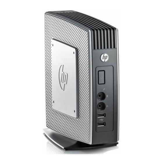
Page 8: Top Components
Universal serial bus (USB) connectors (2) Top Components For more information, http://www.hp.com and search for your specific thin client model to find the model-specific QuickSpecs. The secure USB compartment allows you to use two USB devices in a secured location. -
Page 9: Rear Panel Components
Power connector Secure USB compartment cable routing slot *Available on some models. Refer to the model-specific QuickSpecs at www.hp.com for details. The wireless antenna allows you to send and receive wireless signals to communicate with wireless local area networks (WLAN). -
Page 10: Installing The Antenna (Wireless Models)
Installing the Antenna (Wireless Models) Screw the antenna in place on the rear of the thin client. ▲ Figure 1-5 Installing the antenna CAUTION: To prevent damage to the antenna mounting, do not overtighten the antenna. Installing the Rubber Feet You may want to use your thin client in a horizontal orientation. -
Page 11: Installing The Stand
Align the feet with their holes and press them in securely. Figure 1-6 Installing the rubber feet Installing the Stand If you want to use the thin client in a vertical orientation, you will need to install the stand for stability. To install the stand: Turn unit upside down. -
Page 12: Removing The Stand
Removing the Stand To remove the stand: Turn unit upside down. Press down on the tab (1), and then slide the stand toward the rear of the unit and pull it up to remove it from the unit (2). Figure 1-8 Removing the stand Using the Power Cord Retention Slot To prevent accidental disconnection, press a loop of the power cord into the power cord retention slot. -
Page 13: Using The Keyboard
Using the Keyboard Figure 1-10 Keyboard features Caps Lock Activates/deactivates the Caps Lock feature. Scroll Lock Activates/deactivates the Scroll Lock feature. Num Lock Activates/deactivates the Num Lock feature. Ctrl Use in combination with another key; its function depends on the application software you are using. -
Page 14: Windows Logo Key
Windows Logo Key Use the Windows Logo Key in combination with other keys to perform certain functions available in Windows operating systems. Windows Logo Key + Switch between open items. Windows Logo Key + Open My Computer. Windows Logo Key + Search for a file or folder. -
Page 15: Serial Number Location
Serial Number Location Every thin client includes a unique serial number located as shown in the following illustration. Have this number available when contacting HP customer service for assistance. Figure 1-11 Serial number location Serial Number Location... -
Page 16: Hardware Changes
Hardware Changes General Hardware Installation Sequence To ensure the proper installation thin client hardware components: Back up any data, if necessary. If the thin client is powered on: Turn off the computer properly through the operating system, then turn off any external devices. -
Page 17: Removing And Replacing The Secure Usb Compartment Cover
Turn on the monitor, the thin client, and any devices you want to test. Load any necessary drivers. NOTE: You can download select hardware drivers from HP. Go to http://www.hp.com search for your specific thin client model. Reconfigure the thin client, if necessary. -
Page 18: Replacing The Secure Usb Compartment Cover
Push the compartment cover about .6 cm (1/4 inch) toward the front of the unit (2) and lift it off the unit (3). Figure 2-1 Removing the secure USB compartment cover Replacing the Secure USB Compartment Cover To replace the secure compartment cover: Place the cover on top of the unit so it is offset about 0.6 cm (1/4 inch) toward the front of the unit, allowing the tabs on the cover to align with the slots on the chassis (1). - Page 19 To remove the access panel: Remove the secure compartment cover (1). For more information, see Removing the Secure USB Compartment Cover on page Remove the stand, if it is installed. See Removing the Stand on page 6 for more information. Lay the unit flat on a stable surface with the right side up and the left side down.
-
Page 20: Replacing The Metal Side Cover And Side Access Panel
Replacing the Metal Side Cover and Side Access Panel To replace the metal side cover: Slip the front edge of the metal side cover under the lip on the chassis, lower the front edge, and then press the metal side cover down into place (1). Insert and tighten the four screws (2). -
Page 21: Installing Thin Client Options
Installing Thin Client Options Various options can be installed on the thin client: Installing the USB Device on page 15 ● Removing and Replacing the Battery on page 16 ● Installing a Secondary Flash Memory Module on page 18 ● External Drives on page 19 ●... -
Page 22: Removing And Replacing The Battery
If you install a USB mouse and a USB keyboard in the secure USB compartment, route the cables around and through the clips, then out the secure cable routing slot, as shown in the following illustration. Figure 2-7 Using the secure cable routing slot Removing and Replacing the Battery Before beginning the replacement process, review General Hardware Installation Sequence... - Page 23 Slide one edge of the battery into the slot and push down until the guard snaps over the edge of the battery. HP encourages customers to recycle used electronic hardware, HP original print cartridges, and rechargeable batteries. For more information about recycling programs, go to http://www.hp.com...
-
Page 24: Installing A Secondary Flash Memory Module
Installing a Secondary Flash Memory Module Before beginning the installation process, review General Hardware Installation Sequence on page 10 for procedures you should follow before and after installing or replacing hardware. WARNING! You must remove the right side panel to access the system board. Before removing the side access panel, ensure that the thin client is turned off and the power cord is disconnected from the electrical outlet. -
Page 25: External Drives
For more information about available options, visit the HP Web sitehttp://www.hp.com and search for your specific thin client model. -
Page 26: Appendix A Specifications
** The operating temperature range when the thin 1° C/300m (1.8° F/1000ft) to a maximum of 3Km client is attached to a flat panel using the HP Quick (10,000ft), with no direct, sustained sunlight. Upper limit Release is 50° to 95° F (10° to 35° C). - Page 27 Table A-1 HP t510 Thin Client (continued) Rated Output Current (maximum) 3.42 A 3.42 A Output Voltage +19 V DC +19 V DC...
-
Page 28: Appendix B Security Provisions
Securing the Thin Client These thin clients are designed to accept a security cable lock. This cable lock prevents unauthorized removal of the thin client, as well as locking the secure compartment. To order this option, visit the HP Web site at http://www.hp.com... -
Page 29: Appendix C Mounting The Thin Client
HP Quick Release connects to the VESA-standard mounting points, allowing you to mount the thin client in a variety of orientations. NOTE: When mounting to a thin client, use the 15 mm screws supplied with the HP Quick Release. Figure C-1 HP Quick Release... - Page 30 To use the HP Quick Release: Using four 15 mm screws included in the mounting device kit, attach one side of the HP Quick Release to the thin client as shown in the following illustration. Figure C-2 Connecting the HP Quick Release to the thin client Using four screws included in the mounting device kit, attach the other side of the HP Quick Release to the device to which you will mount the thin client.
-
Page 31: Supported Mounting Options
Figure C-4 Connecting the thin client NOTE: When attached, the HP Quick Release automatically locks in position. You only need to slide the lever to one side to remove the thin client. CAUTION: To ensure proper function of the HP Quick Release and a secure connection of all components, make sure both the release lever on one side of the mounting device and the rounded opening on the other side face upward. - Page 32 Figure C-6 Thin client mounted on back of monitor stand Figure C-7 Thin client mounted on wall Figure C-8 Thin client mounted under desk Appendix C Mounting the Thin Client...
-
Page 33: Non-Supported Mounting Option
Non-supported Mounting Option CAUTION: Mounting a thin client in an non-supported manner could result in failure of the HP Quick Release and damage to the thin client and/or other equipment. Do not mount the thin client on a flat panel monitor stand, between the panel and the stand. -
Page 34: Appendix D Thin Client Operation
Thin Client Operation Routine Thin Client Care Use the following information to properly care for your thin client: Never operate the thin client with the outside panel removed. ● Keep the thin client away from excessive moisture, direct sunlight, and extreme heat and cold. For ●... -
Page 35: Supported Orientations
Supported Orientations HP supports the following orientations for the thin client. CAUTION: You must adhere to HP-supported orientations to ensure your thin clients function properly. Figure D-1 Vertical orientation using the supplied stand Figure D-2 Horizontal orientation on rubber feet... -
Page 36: Non-Supported Orientation
Non-supported Orientation HP does not support the following orientation for the thin client. CAUTION: Non-supported placement of thin clients could result in operation failure and/or damage to the devices. CAUTION: Thin clients require proper ventilation to maintain operating temperature. Do not block the vents. -
Page 37: Appendix E Electrostatic Discharge
● Use a portable field service kit with a folding static-dissipating work mat. ● If you do not have any of the suggested equipment for proper grounding, contact an HP authorized dealer, reseller, or service provider. NOTE: For more information about static electricity, contact an HP authorized dealer, reseller, or service provider. -
Page 38: Appendix F Shipping Information
Specifications on page 20 Important Service Repair Information In all cases, remove and safeguard all external options before returning the thin client to HP for repair or exchange. In countries that support customer mail-in repair by returning the same unit to the customer, HP makes every effort to return the repaired unit with the same internal memory and flash modules that were sent. -
Page 39: Index
5 SATA flash memory module rear panel 3 top 2 stand 5 parallel connector 3 thin client onto HP Quick power button location 1 dimensions 20 Release 23 power connector location 3 diskette drive 19 USB devices 1, 11, 15... - Page 40 10, 11, 12, 16, service repair 32 shipping preparation 32 fire 10 shutting down 10 Web sites side access panel HP 1 removing 12 options 1 replacing 14 weight 20 side cover Windows Logo Key 7 removing 12...