Canon imageprograf ipf700 Service Manual
Hide thumbs
Also See for imageprograf ipf700:
- Service manual (172 pages) ,
- Brochure (10 pages) ,
- Quick start manual (8 pages)

Related Manuals for Canon imageprograf ipf700


Summary of Contents for Canon imageprograf ipf700
- Page 1 SERVICE MANUAL DU7-1183-000 JULY 2006 REV. 0 COPYRIGHT 2006 CANON INC. CANON imagePROGRAF iPF700 REV. 0 PRINTED IN U.S.A.
- Page 2 This manual may contain technical inaccuracies or typographical errors due to improvements or changes in products. When changes occur in applicable products or in the contents of this manual, Canon will release technical information as the need arises. In the event of major changes in the contents of this manual over a long or short period, Canon will issue a new edition of this manual.
-
Page 3: Symbols Used
Introduction Symbols Used This documentation uses the following symbols to indicate special information: Symbol Description Indicates an item of a non-specific nature, possibly classified as Note, Caution, or Warning. Indicates an item requiring care to avoid electric shocks. Indicates an item requiring care to avoid combustion (fire). Indicates an item prohibiting disassembly to avoid electric shocks or problems. - Page 4 Introduction The following rules apply throughout this Service Manual: 1. Each chapter contains sections explaining the purpose of specific functions and the relationship between elec- trical and mechanical systems with reference to the timing of operation. In the diagrams, represents the path of mechanical drive; where a signal name accompanies the symbol, the arrow indicates the direction of the electric signal.
-
Page 5: Table Of Contents
Contents Contents Chapter 1 PRODUCT DESCRIPTION 1.1 Product Overview....................1-1 1.1.1 Product Overview....................... 1-1 1.2 Features......................1-2 1.2.1 Features........................1-2 1.2.2 Printhead ........................1-3 1.2.3 Ink tanks ........................1-3 1.2.4 Cutter unit........................1-4 1.2.5 Roll holder ........................1-4 1.2.6 Expendables ....................... 1-4 1.3 Product Specifications.................. - Page 6 Contents 1.7.3.4 Precautions for Disassembly/Reassembly..............1-31 1.7.3.5 Self-diagno stic Feature ....................1-31 1.7.3.6 Disposing of a lithium battery ................... 1-31 Chapter 2 TECHNICAL REFERENCE 2.1 Basic Operation Outline ..................2-1 2.1.1 Printer Diagram ......................2-1 2.1.2 Print Driving........................ 2-2 2.2 Firmware ......................2-2 2.2.1 Operation Sequence at Power-on ................
- Page 7 Contents 2.4.5.1 Maintenance cartridge relay PCB components ............. 2-31 2.4.6 Power Supply ......................2-31 2.4.6.1 Power supply block diagram..................... 2-31 2.5 Detection Functions with Sensors ..............2-32 2.5.1 Sensers for covers ....................2-32 2.5.2 Ink passage system ....................2-33 2.5.3 Carriage system ....................... 2-36 2.5.4 Paper path system ....................
- Page 8 Contents 4.4 Applying the Grease ..................4-28 4.4.1 Applying The Grease ....................4-28 4.5 Adjustment and Setup Items ................4-30 4.5.1 Procedure after Replacing the Feed Roller HP Sensor or Feed Roller Encoder 4- 4.5.2 Procedure after Replacing the Carriage Unit or Multi Sensor......4-30 4.5.3 Procedure after Replacing the Head Management Sensor ......
- Page 9 Contents 03860002-2E0A/03860002-2E0C Path mismatch error ............6-7 6.1.4.6 03030000-2E21 IEEE1394 Error ..................6-8 6.1.4.7 03031000-2E0F Upper cover sensor error ..............6-8 6.1.4.8 03031000-2E11 Carriage cover sensor error ..............6-8 6.1.4.9 03031000-2E12 Defective paper release lever .............. 6-9 6.1.4.10 03060A00-2E1B Roll media end error ................6-9 6.1.4.11 03130031-260E Gap detection error................
- Page 10 Contents 6.1.5.5 E194-404A Non-discharge detection count error ............6-18 6.1.5.6 E196-4040/E196-4041/E196-4042/E196-4043/E196-4044/E196-4045 Main controller PCB error............................ 6-18 6.1.5.7 E198-401C/E198-401D/E198-401E RTC error ............6-19 6.2 Location of Connectors and Pin Arrangement ..........6-19 6.2.1 Main controller PCB ....................6-19 6.2.2 Carriage relay PCB ....................6-28 6.2.3 Head relay PCB.......................
-
Page 11: Chapter 1 Product Description
Chapter 1 PRODUCT DESCRIPTION... - Page 12 Contents Contents 1.1 Product Overview....................1-1 1.1.1 Product Overview....................... 1-1 1.2 Features......................1-2 1.2.1 Features........................1-2 1.2.2 Printhead ........................1-3 1.2.3 Ink tanks ........................1-3 1.2.4 Cutter unit........................1-4 1.2.5 Roll holder ........................1-4 1.2.6 Expendables ....................... 1-4 1.3 Product Specifications..................1-5 1.3.1 Product Specifications....................
-
Page 13: Product Overview
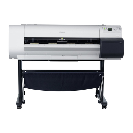
Chapter 1 1.1 Product Overview 1.1.1 Product Overview 0012-6185 This printer is a large-format printer that prints in a maximum width of 36 inches with high-speed photographic picture quality. This printer is a desktop product that delivers its output on roll or cut media. [10] [11] [12]... -
Page 14: Features
Chapter 1 1.2 Features 1.2.1 Features 0012-6186 -Rear loading of roll media, making for compact, lightweight device geometry. -Borderless four-side printing support (roll media) removes laborious cutting work, easing the job of creating posters to a significant degree. -High resolutions of 2400 x 1200 dpi maximum, coupled with the exceptionally light-fast, water-proof and ozone-proof five-color pigment inks of Y, M, C, BK and MBK, deliver high-quality photographic picture quality. -
Page 15: Ink Tanks
Chapter 1 1.2.3 Ink tanks 0013-0607 Ink tanks are disposable. An ink tank should be replaced when an ink tank replacement prompt message appears or when six months expire after the date of initial unpacking, whichever occurs earlier. To install ink tanks, open the right cover of the printer. Ink tanks are furnished with a notch for preventing incorrect installation, which will allow the tanks to be installed at the position marked in the right color and nowhere else. -
Page 16: Roll Holder
Chapter 1 1.2.5 Roll holder 0013-4667 The printer comes with a roll holder for paper tubes having an inside diameter of 2 inches as standard. It supports an optional roller holder for paper tubes having an inside diameter of 3 inches. Both roll holders clamp the paper tubes of roll media with an outside diameter of 150 mm or less from inside. -
Page 17: Product Specifications
Chapter 1 c. Maintenance cartridge The expendable maintenance cartridge is the same as the one that comes with the printer. The maintenance cartridge is furnished with a shaft cleaner. F-1-8 1.3 Product Specifications 1.3.1 Product Specifications 0012-6192 Type Bubble-jet printer (desktop type) Feeding system Roll media: Manual (Rear loading) Cut media: Paper tray (Front loading) - Page 18 Chapter 1 Printable area (Roll media) Bordered printing: Internal area, excluding 3-mm top, bottom, and left and right margins. Borderless printing: Internal area, excluding 0-mm top, bottom, and left and right margins. * The printable area may vary with each type of paper media used.
- Page 19 Chapter 1 Operating environment Temperature: 15-30 oC Relative humidity: 10-80%RH (non-condensing) Print quality guaranteed Temperature: 15-30 oC environment Relative humidity: 10-80%RH Power supply AC 100 V - 240 V (50 Hz/60 Hz) Power consumption 140 W or less (Maximum) Power consumption When idle in energy save mode (sleep mode) 100-120 V: 5.0 W or less (with IEEE1394 mounted, 8 W or less)
-
Page 20: Detailed Specifications
Chapter 1 1.4 Detailed Specifications 1.4.1 Print speeds and print directions 0013-6386 T-1-2 Mediatype Prioritized picture Print quality Number of Direction Resolution quality passes (*1) Plain paper Photographs and Fast 1 pass Bidirectional 1200 x 1200 dpi Plain paper (bond paper) illustrations Standard 2 passes... -
Page 21: Interface Specifications
Chapter 1 Mediatype Prioritized picture Print quality Number of Direction Resolution quality passes (*1) Tracing paper(CAD) Line drawings and Fast (*2) 1 pass Bidirectional 1200 x 1200 dpi translucent mat films(CAD) text 1 pass Bidirectional 1200 x 1200 dpi Standard 2 passes Bidirectional 1200 x 1200 dpi Fine (* 2) -
Page 22: Names And Functions Of Components
Chapter 1 c. [IEEE1394] (option) (1) Interface Type IEEE1394-1995, P1394a (Version 2.0)-compliant interface (2) Method of data transfer Asynchronous transfer (3) Signal levels Input: Differential input voltage: +173mV - +260mV during S100 arbitration +142mV - +260mV, receiving data +171mV - +262mV during S200 arbitration +132mV - +260mV, receiving data +168mV - +265mV during S400 arbitration +118mV - +260mV, receiving data... -
Page 23: Printer Rear Panel
Chapter 1 1.5.2 Printer rear panel 0013-4638 F-1-10 [1] Release lever Releases the paper retainer. Press this lever rearward to load paper or clean the interiors of the printer. [2] Power connector Connect the power cord to this connector. [3] Roller holder slot Set the roll holder in this guide slot. -
Page 24: Carriage
Chapter 1 1.5.3 Carriage 0013-4655 F-1-11 [1] Carriage cover Protects the carriage. [2] Printhead fixer cover Clamps the printhead. [3] Printhead A key component that houses nozzles. [4] Shaft cleaner Keeps the carriage shaft clean. [5] Printhead fixer lever Locks the printhead fixer cover. [6] Slant adjustment lever Fine-adjusts slants in ruled lines during printing. -
Page 25: Basic Operation
Chapter 1 1.6 Basic Operation 1.6.1 Operation panel 0012-6207 The functions of the keys and meanings of LED indications on the operation panel are described below. [14] Data Online Power Infomation Message [13] Cleaning (3 Sec.) Menu Eject Stop [12] [10] [11] F-1-12... -
Page 26: Printer State Transitions
Chapter 1 Keys [Menu mode] " key" Opens the menu one level above. " key" Opens the menu one level lower. " key" Displays the previous action or setting. " key" Displays the next action or setting. [Offline mode] " key"... -
Page 27: Main Menu
Chapter 1 1.6.3 Main menu 0012-6209 This printer supports a main menu that offers an organized clue to opening a maintenance menu for adjusting the discharge position of each nozzle, cleaning the printhead and so on, a print setup menu for setting the auto- cutting feature, the ink drying time and so on, a parameters menu for selecting a message display language and so on, and more.. - Page 28 Chapter 1 b. Main menu List The hierarchy and settings of the main menus are described below. MAIN MENU Force Cutting Rep.Ink Tank Head Cleaning Head Cleaning A Head Cleaning B Media Menu Roll Media Type (Select media type) Chk Remain.Roll Roll Length Set * Displayed only when "On"...
- Page 29 Chapter 1 Paper Details MENU Paper Details Drying_Time (30sec. 1min. 3min. 5min. 10min. 30min.) 60min. Scan Wait Time (1sec. 3sec. 5sec. 7sec.) 9sec. Feed Priority Automatic Band Joint Print Length Print Length -0.70% 0.70% Head Height Automatic (Lowest Low Standard High) Highest Skew Check Lv.
- Page 30 Chapter 1 Adjust Printer Menu Adjust Printer Auto Head Adj. Standard Adj. Advanced Adj. Auto Print Manual Head Adj Auto Band Adj. Standard Adj. Advanced Adj. Manual Band Adj Adjust Band Adjust Length Head Inc.Adj. F-1-16 1-18...
- Page 31 Chapter 1 Interface Setup Menu Interface Setup EOP Timer 10sec. (30sec. 1min. 2min. 5min. 10min. 30min.) 60min. TCP/IP TCP/IP IP Mode Automatic Manual Protocol DHCP BOOTP RARP IP Setting IP Address ( 0-255 0-255 0-255 0-255 ) Subnet Mask ( 0-255 0-255 0-255 0-255 ) Default G/W ( 0-255 0-255 0-255 0-255 ) NetWare...
- Page 32 Chapter 1 System Setup Menu System Setup Warning Buzzer Ignore Mismatch Keep Media Size Judge Paper Size Sht Selection 1 ISO A3+ ANSI B Super Sht Selection 2 ISO B1 ANSI F Roll Selection 1 ISO A3+(297mm) 300m Roll Roll Selection 2 10inch(254mm) JIS B4(257mm) Noz.Check Freq.
- Page 33 Chapter 1 Time Zone Time Zone London (GMT) +1 Paris,Rome +2 Athens.Cairo +3 Moscow +4 Eerevan,Baku +5 Islamabad +6 Dacca +7 Bangkok +8 Hong Kong +9 Tokyo,Seoul +10 Canberra +11 NewCaledonia +12 Wellington Eniwetok Midway is. Hawaii (AHST) Alaska (AKST) Oregon (PST) Arizona (MST) Texas (CST)
-
Page 34: Safety And Precautions
Chapter 1 1.7 Safety and Precautions 1.7.1 Safety Precautions 1.7.1.1 Moving parts of the printer 0013-5153 Be careful not to get your hairs, clothing, accessories or any other objects caught in the moving parts of the printer. The moving parts of the printer include the carriage unit, carriage belt, ink tube, flexible cable and feed motor driven by the carriage motor and the feed and pinch rollers driven by the feed motor and the purge unit driven by the purge motor. -
Page 35: Ink Adhesion
Chapter 1 1.7.1.2 Ink adhesion 0013-5154 a. Ink passage Be careful not to touch the ink passage in the printer to get the printer being serviced, workbench, your hands and clothes and so on smeared by the ink. The ink passage comprises the ink tank unit, carriage unit, purge unit, maintenance cartridge unit and the ink tubes that interconnect the separate parts. - Page 36 Chapter 1 b. Ink mists As the printhead jets an ink against paper to print, traces of ink mists floating during printing or springing back from the paper are produced in the print station. Such ink mists are collected by mist collection air flow into the printer.
-
Page 37: Live Parts Of The Printer
Chapter 1 1.7.1.3 Live parts of the printer 0013-5155 Any electrical portion of the printer becomes live when AC power is supplied to it. The main controller, power supply and interface connector are found on the left rear side of the printer, with the operation panel being located on the upper right cover. -
Page 38: Other Precautions
Chapter 1 1.7.2 Other Precautions 1.7.2.1 Printhead 0013-1936 a. Handling the printhead Do not unpack the printhead until it is ready for immediate use. When mounting the printhead on the printer, remove protective caps 1 and 2 in this order by holding them by the lugs. - Page 39 Chapter 1 b. Capping action The printer performs a capping action at the end of printing or when it stands by in the wake of an error occurrence, to protect the printhead and prevent ink leaks. If the printer has been powered off by inadvertently disconnecting the power cord from the wall outlet, reconnect the power cord to the wall out and turn on the power key.
-
Page 40: Ink Tanks
Chapter 1 1.7.2.2 Ink tanks 0012-6229 a. Opening ink tanks Do not unpack ink tanks until they are ready for immediate use. When placing an ink tank in position, shake it slowly seven to eight times before opening it. Without shaking, the ingredients of the ink might settle, resulting in degraded print quality. -
Page 41: Dealing With The Printer
Chapter 1 1.7.2.3 Dealing with the printer 0013-1880 a. Protecting against electrostatic breakdowns Pieces of clothing rubbing each other could build up static electricity, producing static charges in human bodies to cause harm to an electrical component or corrupt its electrical characteristics. You are strongly advised never to touch the printhead contact of the carriage. -
Page 42: Precautions When Servicing Printer
Chapter 1 1.7.3 Precautions When Servicing Printer 1.7.3.1 Tips on data stored in the printer 0013-5152 This printer memorizes the print length, how many times tanks have been replaced, how long the carriage has been driven, how many times the printhead has been cleaned, how many times the cutter has been actuated and so forth, and stores such statistics in service mode counters in EEPROM on the main controller. -
Page 43: Precautions For Disassembly/Reassembly
Chapter 1 1.7.3.4 Precautions for Disassembly/Reassembly 0013-5150 Disassembly/reassembly tips can be found in Disassembly/Reassembly. 1.7.3.5 Self-diagno stic Feature 0013-5151 The printer comes with built-in self-diagnostics to analyze hardware malfunctions as they occur. Displays and LED indications provide a visual identification of the results of self-diagnostics. For more details, see the error indication section of Error Codes. -
Page 44: Chapter 2 Technical Reference
Chapter 2 TECHNICAL REFERENCE... - Page 45 Contents Contents 2.1 Basic Operation Outline ................... 2-1 2.1.1 Printer Diagram ......................2-1 2.1.2 Print Driving......................... 2-2 2.2 Firmware......................2-2 2.2.1 Operation Sequence at Power-on ................2-2 2.2.2 Operation Sequence at Power-off ................2-3 2.2.3 Print Control ........................ 2-3 2.2.4 Print Position Adjustment Function ................. 2-6 2.2.5 Head Management ....................
- Page 46 Contents 2.4.5.1 Maintenance cartridge relay PCB components............. 2-31 2.4.6 Power Supply ......................2-31 2.4.6.1 Power supply block diagram .................... 2-31 2.5 Detection Functions with Sensors..............2-32 2.5.1 Sensers for covers ....................2-32 2.5.2 Ink passage system ....................2-33 2.5.3 Carriage system ...................... 2-36 2.5.4 Paper path system ....................
-
Page 47: Basic Operation Outline
Chapter 2 2.1 Basic Operation Outline 2.1.1 Printer Diagram 0012-6242 A printer diagram is shown below. Printhead J601 Ink tank ROM PCB (L) Ink tank ROM PCB (R) Valve motor Valve open/closed detection Sensor J202 J201 Ink tank cover switch Linear encoder Humidity sensor Carriage cover sensor... -
Page 48: Print Driving
Chapter 2 2.1.2 Print Driving 0013-5398 At printing, print signals and control signals are output to the printhead via the carriage relay PCB and Head relay PCB to discharge inks from the nozzle assembly. The printhead six trains of nozzles arranged in a zigzag pattern. This printer uses only one printhead. -
Page 49: Operation Sequence At Power-Off
Chapter 2 2.2.2 Operation Sequence at Power-off 0013-5400 Turning off the power switch cuts off the drive voltage supply, launching a firmware power-off sequence as shown below. If the power cord is disconnected from the wall outlet or the top cover or any other cover is opened, the printer cancels the ongoing operation and shuts down immediately. - Page 50 Chapter 2 Imaging data prints in one to six (one, two, four or six) passes per band (equivalent of the length of a nozzle). Select Standard as a print quality setting of the print driver to enable standard mode. (3) High quality mode Imaging data prints in two, four or eight passes per band.
- Page 51 Chapter 2 Printing Media Type Print Priority Print Quality Print-pass Print resolution direction(*1) Glossy Photo Paper Image Standard 6pass Bi-directional 1200x1200dpi Glossy Photo Paper2 High 8pass Bi-directional 2400x1200dpi Semi-Glossy Photo Highest Paper Semi-Glossy Photo Paper2 Heavyweight Glossy Photo Paper Heavyweight SemiGlos Photo Paper 16pass...
-
Page 52: Print Position Adjustment Function
Chapter 2 2.2.4 Print Position Adjustment Function 0012-6248 This printer supports a print position adjustment function to adjust the vertical and horizontal print position and the bidirectional print position of the print head mounted on the carriage and the feed rate. Print position adjustment work in two modes: automatic adjustment, in which print position adjustment patterns printed are detected by a multisensor attached to the lower left part of the carriage, and manual adjustment, in which print position adjustment patterns that are slightly modified from one another are printed, so that visually... -
Page 53: Sleep Mode
Chapter 2 2.2.9 Sleep Mode 0012-6255 The printer has sleep mode to save on its standby power requirement. The printer transitions to sleep mode automatically when it has been left idle or no print data has been received for a predetermined period of time while the printer is online or offline. The printer exits sleep mode when any operation panel key is activated or print data is received from the host computer. -
Page 54: Printer Mechanical System
Chapter 2 2.3 Printer Mechanical System 2.3.1 Outline 2.3.1.1 Outline 0012-6256 The printer mechanism is broken down into two broad sections: the passage and paper passage. Consisting mainly of a carriage unit that houses ink tanks and a printhead, and a maintenance cartridge, the ink passage supplies, circulates, sucks and otherwise handles inks. -
Page 55: Ink Passage
Chapter 2 2.3.2 Ink Passage 2.3.2.1 Ink Passage 2.3.2.1.1 Overview of Ink Passage 0013-6730 The ink passage comprises ink tanks, a printhead, caps, a waste ink collector, ink tubes interconnecting the mechanical components, and a suction pump that is driven to suck inks. It supplies, circulates, sucks and otherwise handles inks. -
Page 56: Ink Tank Unit
Chapter 2 unit. d) Ink supply while printing The ink supply valves are kept open while printing, so that inks are being constantly fed to the printhead under the negative pressure of the nozzle assembly caused by discharging inks. Further, waste inks sucked in a cleaning operation and inks from borderless printing flow into the waste ink absorber under the maintenance cartridge or purge unit and into the waste ink box. - Page 57 Chapter 2 e) Agitating plate Assists in the agitation of pigment inks during ink agitation carried out to prevent their settlement. Notches for preventing Notches for preventing incorrect installation incorrect installation Air passage Ink port EEPROM Agitation plate Notches for preventing incorrect installation Ink tank F-2-6...
- Page 58 Chapter 2 f) Ink supply valves Located halfway between the ink tanks and the ink tubes, the ink supply valves prevent the leakage of inks that might otherwise be caused by the opening of the ink tubes on the side of the ink tanks during their replacement. The ink supply valves are caused to open and close by the valve open/close mechanism that is activated by driving the valve motors.
-
Page 59: Carriage Unit
Chapter 2 2.3.2.3 Carriage Unit 2.3.2.3.1 Functions of Carriage Unit 0013-5642 a) Printhead mounting function The carriage, which fixes the printhead in position mechanically, is connected to the contact of the head relay PCB. b) Control function The carriage carries a carriage relay PCB, which relays printhead drive signals, and an encoder, which generates print timing signals. - Page 60 Chapter 2 2.3.2.3.2 Structure of Carriage Unit 0012-6265 a) Printhead mount The printhead is secured to the carriage by the printhead fixer cover and the printhead fixer lever. When the printhead is secured to the carriage, the signal contact of the head relay PCB is pressed against that of the printhead to convey print signals.
- Page 61 Chapter 2 Head relay PCB Carriage relay PCB multi sensor Sensor Flag Maintenance-jet tray Carriage cover sensor lift cam sensor F-2-9 e) Printhead maintenance unit This printer cleans the printhead with the carriage halted at its home position. Wiping is executed in sync with the rotation of the motor. Wipers mounted on the carriage wipe the printhead while the carriage is halted at its home position.
-
Page 62: Printhead
Chapter 2 2.3.2.4 Printhead 2.3.2.4.1 Structure of Printhead 0013-6742 The printhead is an integrated assembly of six trains of nozzles. Capable of controlling each nozzle individually, the printhead implements discharge control for six colors by itself. a) Nozzle arrangement The nozzle assembly is formed of 1,280 nozzles arranged at 600-dpi intervals in a zigzag pattern, offering a total of 2,560 nozzles 1,200-dpi intervals. -
Page 63: Purge Unit
Chapter 2 b) Nozzle assembly structure Inks supplied from the ink tanks are filtered through a mesh ink filter before being sent to the nozzle assembly. Each nozzle train is supplied with an ink from the common nozzle chamber. When a head drive current flows through the nozzle heater, the ink boils, generating bubbles to discharge ink drops from the nozzle from the nozzle assembly. - Page 64 Chapter 2 Cleaning Name Description of cleaning mode Fills the empty tube (during initial installation) with Cleaning 3 Initial filling ink ink, and then performs normal cleaning. Ink drainage for head Drains ink to replace the head (drains only the ink in Cleaning 4 replacement the head).
- Page 65 Chapter 2 The cleaning operation is executed at the following timing: T-2-4 Printer status Description of cleaning During standby Each time 120 minutes have elapsed Cleaning 1 with the nozzles capped (normal cleaning) When 168 hours have elapsed since Idle ejection capping When 360 hours have elapsed since Cleaning 2 (ink level adjusting cleaning)
-
Page 66: Purge Unit
Chapter 2 Printer status Description of cleaning When "Head Cleaning" menu Manual cleaning (head cleaning A) Cleaning 1 (normal cleaning) is selected Manual cleaning (head cleaning B) Cleaning 6 (normal (strong) cleaning) When "Replace Head" menu After replacement of head Cleaning 2 (fluid level cleaning) + Cleaning 4 (ink is selected drainage after head replacement) - Page 67 Chapter 2 a) Caps The caps cap the nozzle assembly in the printhead during cleaning. The part of the caps that comes into contact with the face plate of the nozzle assembly is made of rubber. Two caps are in position to meet the printhead mounted on the printhead (six trains of nozzles).
- Page 68 Chapter 2 b) Wipers The wipers are driven by the purge motor to wipe the face of the printhead. A pair of two wiper blades are installed to ensure wiping performance. The wiping operation operates on a slide wiping basis, sliding the wiper blades via wiper cams through the rotation (normal) of the purge motor.
-
Page 69: Maintenance Cartridge
Chapter 2 c) Pump The pump (suction pump) is a tube pump that pressurizes the ink tubes with rotating rollers to generate a negative pressure for sucking inks. A single tube is sequentially pressurized by a pair of rotating rollers to control the level of ink suction. The timing at which the rotating rollers rotate is detected by the pump cam sensor, with the distance of rotation being controlled by the driving of the purge motor. -
Page 70: Air Flow
Chapter 2 2.3.2.7 Air Flow 2.3.2.7.1 Air flow 0012-6276 This printer is furnished with two fans: a mist fan, which collects ink mist, and a platen fan, which allows paper to be adsorbed on the plate, and a platen fan. Ink mist floating during printing or bouncing back from the paper is collected in the maintenance cartridge by airflow in the printer. -
Page 71: Paper Path
Chapter 2 Basic operation of the paper loading sequence 1) Light intensity 2) Detection of leading edge of media 3) Paper width detection sensor Detects the left and right edges of paper. 4) Barcode read *This function is operable only if the remaining roll media detection sensor is turned on. 5) Ditection of leading skew of media. -
Page 72: Cutter Unit
Chapter 2 Pinch roller Paper release lever Cut sheet Feed roller F-2-19 2.3.3.3 Cutter Unit 2.3.3.3.1 Structure of the cutter unit 0012-6289 a) Sheet cutter When "Autocut: Yes" is selected in the Printer Driver, the cutter unit mounted on the left side of the carriage automatically cuts the roll media. -
Page 73: Printer Electrical System
Chapter 2 2.4 Printer Electrical System 2.4.1 Outline 2.4.1.1 Overview 0012-6291 The printer electrical system consists of the main controller PCB and power supply PCB which are mounted on the back side of the printer, the carriage relay PCB, the head relay PCB, and printhead which are mounted in the carriage, the operation panel on the right upper cover and other electrical components such as sensors, and motors. -
Page 74: Main Controller
Chapter 2 2.4.2 Main Controller 2.4.2.1 Main controller components 0013-8235 IC3203 IC2802 IC601 IC2902 IC602 IC603 IC604 IC2900 IC701 IC3100 IC802 F-2-22 a) ASIC (IC2) The ASIC with a 16-bit internal bus is driven in sync with the 66 MHz external clock. It supports the following functions: Image processing unit This unit converts the RGB multi-bit image data or CMYK multi-bit data received from the host computer... - Page 75 Chapter 2 PWM control function This function controls driving of the suction fan and mist fan as well as the temperature of the printhead. Remaining ink level detection function This function detects the remaining level of each color of ink based on the signal received from the hollow needle mounted in the ink tank unit.
-
Page 76: Carriage Relay Pcb
Chapter 2 2.4.3 Carriage Relay PCB 2.4.3.1 Carriage relay PCB components 0012-6316 IC302 IC701 F-2-23 a) Receiver ASIC (IC701) This ASIC relays the image data which are output from the main controller. This ASIC does not process the image data. b) Regulator IC (IC302) This IC generates power for the printhead heater. -
Page 77: Maintenance Cartridge Relay Pcb
Chapter 2 controller through the carriage relay PCB. c) Multi sensor control IC (IC204, IC205) These IC's generates the LED control signals and makes gain adjustment for the multi sensor. 2.4.5 Maintenance Cartridge Relay PCB 2.4.5.1 Maintenance cartridge relay PCB components 0013-6972 IC 1 F-2-25... -
Page 78: Detection Functions With Sensors
Chapter 2 2.5 Detection Functions with Sensors 2.5.1 Sensers for covers 0012-6321 Upper Cover lock switch(left) Upper cover lock switch(right) Ink tank cover switch F-2-27 Upper cover lock switch The micro switch-based Upper cover lock switch detects the open/closed states of the upper cover. When the upper cover closes, the switch is pressed to detect the closed state of the cover. -
Page 79: Ink Passage System
Chapter 2 2.5.2 Ink passage system 0013-8100 Head management sensor Purge unit Pump cam sensor Pump encoder Valve open/closed detection sensor F-2-28 2-33... - Page 80 Chapter 2 Pump cam sensor As the cam rotates, it shields the sensor light of the photointerrupter-based pump cam sensor or allows it to be transmitted. The status of the purge unit, such as capped, suction, and wiping, is detected in a combat ion of the status of detection by the pump cam sensor and the control of purge motor rotation by the pump encoder sensor.
- Page 81 Chapter 2 Ink detection sensor The ink detection sensor detects the presence or absence of the ink in an ink tank with respect to the status of continuity between two hollow needles. When the ink level in the tank falls to a point below the wall surrounding the hollow needles in the air passage, continuity with the hollow needle on the ink supply side is disrupted, causing the sensor to detect that is ink is out.
-
Page 82: Carriage System
Chapter 2 2.5.3 Carriage system 0012-6325 HeadrelayPCB Linear encoder multisensor Carriage cover sensor lift cam sensor F-2-33 2-36... - Page 83 Chapter 2 Multisensor The photoreflector-based multisensor consists of four LEDs (red, blue, green, infrared) and two light-receiving sensors to detect the leading edges and width of paper and skews in it, and to adjust its registration, head height and calibration. At head height adjustment, the two light-receiving sensors detect infrared light reflected upon the paper to work out the head height form differences in its measurement.
-
Page 84: Paper Path System
Chapter 2 2.5.4 Paper path system 0012-6327 Feed roller HP sensor Feed roller encoder Media sensor F-2-35 Media sensor The photoreflector-based media sensor detects the presence or absence of paper on the platen. The sensor detects the presence of paper when it receives sensor light reflected upon the paper. Feed roller HP sensor The feed roller HP sensor sets an LF eccentricity correction home position by detecting transitions from black (shielded) to white (transmitted), or a reference, in the scale in the code wheel. - Page 85 Chapter 3 INSTALLATION...
-
Page 86: Transporting The Printer
Contents Contents 3.1 Transporting the Printer ..................3-1 3.1.1 Transporting the Printer....................3-1 3.1.1.1 Transporting the Printer ......................3-1 3.1.2 Reinstalling the Printer ....................3-2 3.1.2.1 Reinstalling the Printer......................3-2... - Page 87 Chapter 3 3.1 Transporting the Printer 3.1.1 Transporting the Printer 3.1.1.1 Transporting the Printer 0013-9654 When transporting the printer, the printhead must be capped and stay in the carriage. In spite of this precaution, shocks incurred during transportation can damage the printhead. Print the nozzle check pattern before making preparations for transporting the printer, pint the nozzle check pattern again after installing the printer at the new location, and then compare the two printouts.
-
Page 88: Reinstalling The Printer
Chapter 3 (8) Wait about 15 minutes after completion of the "Move Printer" operation, remove the maintenance cartridge, and then package it so that waste ink does not leak. Check that waste ink is no longer leaking after removing the maintenance cartridge. If it is leaking, install the maintenance cartridge and wait until waste ink no longer leaks. - Page 89 Chapter 4 DISASSEMBLY/REASSEMBLY...
- Page 90 Contents Contents 4.1 Service Parts...................... 4-1 4.1.1 Service Parts....................... 4-1 4.2 Disassembly/Reassembly................4-1 4.2.1 Disassembly/Reassembly..................4-1 4.3 Points to Note on Disassembly and Reassembly ........4-3 4.3.1 Note on locations prohibited from disassembly ............ 4-3 4.3.2 Manual carriage movement..................4-3 4.3.3 Units required for draining the ink ................
-
Page 91: Service Parts
Chapter 4 4.1 Service Parts 4.1.1 Service Parts 0012-6354 The service parts indicated below require careful handling. 1. Keep all packages with the warning not to turn over. Pay careful attention to all individually packaged service part (carriage unit, purge unit, ink tank unit, and other parts) boxes marked "This side up"... - Page 92 Chapter 4 F-4-2...
-
Page 93: Points To Note On Disassembly And Reassembly
Chapter 4 4.3 Points to Note on Disassembly and Reassembly 4.3.1 Note on locations prohibited from disassembly 0012-6356 Locations that are prohibited from disassembly and cannot be adjusted outside of the factory have red screws instead of the regular-colored screws. F-4-3 4.3.2 Manual carriage movement 0012-6357... -
Page 94: Units Required For Draining The Ink
Chapter 4 4.3.3 Units required for draining the ink 0012-6359 Before disassembling the units in the ink passage mentioned below, drain them of inks completely to prevent their leakage. For instructions on how to drain units of inks, see Disassembly/Reassembly > Tips on Disassembly/Reassembly >... -
Page 95: Outer Covers
Chapter 4 4.3.4 Outer covers 0012-6361 a. Upper cover To detach the upper cover, detach damper cover [1] located on the left and right sides of the back each. Then, fully open the upper cover and slide it to left F-4-5 In attaching the upper cover, have the boss on damper [1] located on both sides into slit [2]. - Page 96 Chapter 4 b. Right side and left side covers To detach a side cover, slide up side cover S [1] in the middle. Unscrew two screws[3] hidden under side cover S [1] and slide downside cover [2] to detach the slide cover. F-4-7 c.
- Page 97 Chapter 4 d. Right upper cover To detach the right upper cover[1], first open the top cover, remove the operation panel, right cover lid and right side cover, and then unscrew the front-panel screws[2]. Next, pull the right side of the right upper cover to front and slide it down out of position by lifting up the upper left edge of the cover.
- Page 98 Chapter 4 f. Front cover To detach the front cover[1], the right cover needs to be removed and the maintenance cartridge cover opened beforehand so the front cover can be slid to right to remove. To do this, unscrew the four front-panel screws[2] and remove two bottom claws[3], and slide the front cover to right.
- Page 99 Chapter 4 g. Upper rear cover To detach the upper rear cover, first remove the top cover, the right rear cover and left front cover, left rear cover and paper release lever. Upper rear cover [1] has upper top claw [2] inserted into cover stay [3]. Rotate the upper edge of the upper rear cover about 90 degrees to detach it.
- Page 100 Chapter 4 i. Paper release lever To remove paper release lever [1], do so with the pinch roller pressurized. In assembling paper release lever [1] into position, align the gear of paper release lever [1] with the mark on the receiving gear (phase) [2]. F-4-14 If pinch roller cam [3] has been overrun when paper release lever [1] is installed, remove cam sensor [4] and replace pinch roller cam [3] in original position.
-
Page 101: Waste Ink Box
Chapter 4 4.3.5 Waste ink box 0013-8085 a. Removing the waste ink box To remove the waste ink box, remove waste ink tray [1] from the back by unscrewing two screws[4]. Then, unscrew four screws[2] to remove waste ink box [3]. F-4-15 4.3.6 Driving unit 0012-6365... -
Page 102: Ink Tube Unit
Chapter 4 b. Action following the replacement of the feed roller HP sensor and feed roller encoder This printer as shipped has the feed roller eccentricity (that is, variations in the rate of paper feed from rotation to rotation) corrected for enhanced media feed accuracy. When the feed roller, feed roller HP sensor or feed roller encoder pertaining to the correction of eccentricity variations has been replaced or disassembled and reassembled, therefore, the feed roller should require adjustment. - Page 103 Chapter 4 (7) Disconnect the joint between the ink tube unit and the ink tank unit. F-4-18 (8) Remove the printhead. (9) Remove printhead fixer lever [1]. (10)Cover the joint of the ink tube unit in a plastic bag or the like to prevent ink splashing and leakage, and seal the mouth of the bag.
- Page 104 Chapter 4 (11)Release the cable cover from its claw away from the frame. (12)Unscrew one screw and remove the cable clamp from the frame. F-4-20 (13)Release the ink tube unit from the carriage. b. Reassembling the ink tube unit When the ink unit has been replaced, turn on the power switch without the printhead and the ink tanks mounted.
-
Page 105: Carriage Unit
Chapter 4 4.3.8 Carriage unit 0012-6371 a. Removing the carriage unit (1) Drain the printer of inks. See Disassembly/Reassembly > Tips on Disassembly/Reassembly > Ink Drain. (2) Switch off the printer and move the carriage to above the platen. See Disassembly/Reassembly > Tips on Disassembly/Reassembly >... - Page 106 Chapter 4 b. Installing the carriage belt Install the carriage belt[2] with its complete set of teeth engaged with carriage belt stopper[1]. F-4-23 c. Action following the replacement of the carriage unit/multi sensor Because the distance between the multisensor (in the carriage unit) and the nozzles (in the printhead) is varied from one unit to another, the printer as shipped has its optical axis corrected to adjust the image write position.
- Page 107 Chapter 4 (7) Remove the printhead fixer lever assembly. (8) Cover the printhead-side joint of the ink tube unit in a plastic bag or the like to prevent ink splashing and leakage, and seal the mouth of the bag. F-4-24 (9) To remove the head holder, press the lock pin located rearward to its left with a flat-blade screwdriver or similar object in the direction of the arrow mark.
- Page 108 Chapter 4 e. Reassembling the head holder After the head holder has been reassembled, check that it lifts up and down in sync with the printhead height adjustment lever. F-4-27 f. Multisensor correction Because the mutisensor is varied from one unit to another, the printer as shipped has the sensor gain and color calibration adjusted for optical axis correction and paper gap calibration purposes.
-
Page 109: Feeder Unit
Chapter 4 4.3.9 Feeder unit 0012-6372 a. Handling the feed roller The feed roller is a functionally vital part. Observe these precautions when handling it: -Do not handle the feed roller with one hand or deflect it. -Do not touch the roller surface (coated side). -Do not flaw or dent the roller surface. -
Page 110: Purge Unit
Chapter 4 4.3.10 Purge unit 0012-6374 b. Removing the purge unit (1) Switch off the printer and move the carriage to above the platen. See Disassembly/Reassembly > Tips on Disassembly/Reassembly > Open Cap/Shift Wiper Unit. (2) Disconnect the ground wire from the side of the purge unit. (3) Remove the connector and release the harness from the harness guide. -
Page 111: Ink Tank Unit
Chapter 4 4.3.11 Ink tank unit 0012-6377 a. Removing the ink tank unit (1) Drain the printer of inks. See Disassembly/Reassembly > Tips on Disassembly/Reassembly > Ink Drain. (2) Remove the joint between the ink tube unit and the ink tank unit. (3) Unscrew four ink tank unit screws and remove five connectors, and then remove the ink tank unit. -
Page 112: Head Management Sensor
Chapter 4 4.3.12 Head management sensor 0012-6375 a. Installing the head management sensor (1) Attach the connector[2] to the head management sensor[1] and then set the head management sensor[1] where it is to be mounted and fasten it with screw. F-4-32 b. -
Page 113: Multi Sensor
Chapter 4 4.3.13 multi sensor 0013-6826 a) Removing the multi sensor (1) The head holder is opened. See: "Disassembly/Reassembly" > "Points to Note on Disassembly/Reassembly" > "Carriage unit" > "d. Removing the head holder" (2) Remove the screw[1], disconnect the flexible cable[2], and then remove the multi sensor[3]. F-4-33 Since multi sensors have individual electrical specificity, the following are recalibrated at the factory, namely, the optical axis of the sensor, the sensor gain for measuring the printhead height and color reproduction. -
Page 114: Pcbs
Chapter 4 - Service mode : SERVICE MODE > ADJUST > GAP CALIB - Service mode : SERVICE MODE > ADJUST > SENSOR CALIB Test chart : CL-7( Tool No. : FY9-9323 Use anew chart.) - Service mode : SERVICE MODE > ADJUST > PRINT PATTERN > OPTICAL AXIS Media type : Photo glossy paper Media size : Media having a width equal toor larger then that of A1-size paper 4.3.14 PCBs... -
Page 115: Opening The Caps And Moving The Wiper Unit
Chapter 4 4.3.15 Opening the Caps and Moving the Wiper Unit 0013-9674 The procedures for manually opening the caps and ink supply valves are presented below. The carriage lock pin and caps need to be released manually if moving the carriage when the power is turned off. -
Page 116: Opening/Closing The Ink Supply Valve
Chapter 4 MEMO: After opening the caps and removing the carriage lock pin, rotating the gear further will close the caps after the wiper unit has completed the return movement, and the carriage lock pin will rise and lock the carriage. 3. -
Page 117: Draining The Ink
Chapter 4 4.3.17 Draining the Ink 0012-6385 There are two methods of removing the ink, using a manual method or automatic method. When the ink is drained, the ink inside the ink passage totaling approximately is drained as waste ink. To prevent ink leaks, be sure to always remove the ink inside the ink passage when disassembling or transporting the parts of the ink passage section. -
Page 118: Applying The Grease
Chapter 4 4.4 Applying the Grease 4.4.1 Applying The Grease 0013-9975 Apply the grease at the location shown below. Smear the grease lightly and evenly with a flat brush. Don't apply the grease to locations other than those designated. Unwanted grease may cause poor print quality, take particular care that grease does not get onto the wiper, cap, or the linear scale. - Page 119 Chapter 4 Bearing Permalube G No.2 approx. 24mg Feed roller Permalube G No.2 Feed roller approx. 24mg Feed roller Permalube G No.2 approx. 24mg F-4-41 Permalube G No.2 approx. 24mg F-4-42 4-29...
-
Page 120: Adjustment And Setup Items
Chapter 4 4.5 Adjustment and Setup Items 4.5.1 Procedure after Replacing the Feed Roller HP Sensor or Feed Roller Encoder 0013-9977 Procedure after replacing the feed roller HP sensor or feed roller encoder Feed roller eccentricity is factory-adjusted (correction of variation in the paper feed amount per rotation). It is necessary to adjust feed roller eccentricity after replacing the feed roller HP sensor or feed roller encoder. - Page 121 Chapter 5 MAINTENANCE...
-
Page 122: Periodic Replacement Parts
Contents Contents 5.1 Periodic Replacement Parts .................. 5-1 5.1.1 Periodic Replacement Parts ...................5-1 5.2 Consumable Parts ....................5-1 5.2.1 Consumable Parts ......................5-1 5.3 Periodic Maintenance ................... 5-1 5.3.1 Periodic Maintenance ....................5-1... -
Page 123: Consumable Parts
Chapter 5 5.1 Periodic Replacement Parts 5.1.1 Periodic Replacement Parts T-5-1 Level Periodic Replacement part User None Service None Personnel 5.2 Consumable Parts 5.2.1 Consumable Parts T-5-2 Level Consumable Durability Remarks (A0) Description part no User See 1 2 6 "Consumable" Service WASTE INK TANK UNIT QM3-1369-000 12000 Sheets... - Page 124 Chapter 6 TROUBLESHOOTING...
- Page 125 Contents Contents 6.1 Troubleshooting....................6-1 6.1.1 Outline ..........................6-1 6.1.1.1 Outline of Troubleshooting....................6-1 6.1.2 Troubleshooting by the Phenomenon ..............6-1 6.1.2.1 Incorrect Value Check Value ....................6-1 6.1.2.2 Load roll..........................6-1 6.1.2.3 Load sheets. /Remove sheets................... 6-2 6.1.2.4 Open Ink Tank Cover......................6-2 6.1.2.5 The printer cannot be turned on.
- Page 126 Contents 6.1.4.20 03130031-2F2A Feed roller home position error ............6-12 6.1.4.21 03130031-2F3A valve open/close error ..............6-12 6.1.4.22 03800200-2802/03800400-2803/03800300-2801 Printhead error ......6-12 6.1.4.23 03800500-280C Defective printhead nozzle .............. 6-13 6.1.4.24 03800500-2F2F/03800500-2F30 Head management sensor error......6-13 6.1.4.25 03810101-2501/03810102-2502/03810103-2503/03810104-2500/03810106-2506/ 03810106-2507 No ink error ....................6-13 6.1.4.26 03810201-2581/03810202-2582/03810203-2583/03810204-2580/03810206-2586/ 03810206-2587 Tank level error 1 ..................
-
Page 127: Troubleshooting
Chapter 6 6.1 Troubleshooting 6.1.1 Outline 6.1.1.1 Outline of Troubleshooting 0013-1941 1. Overview Targets of troubleshooting are classified into the troubles displayed on the LCD (i.e., warnings, errors, and service calls) and the troubles not displayed on the LCD. Warnings and errors are displayed on the printer's LCD along with a code comprising alphanumeric characters. 2. -
Page 128: Load Sheets. /Remove Sheets
Chapter 6 6.1.2.3 Load sheets. /Remove sheets. 0014-0914 <Cause> In the cut media mode, the media sensor detected absence of cut media. When the cut media mode is switched to the roll media mode, the media sensor detected presence of paper. <Probable fault location>... -
Page 129: The Printer Is Shut Down During Power-On Or Printing
Chapter 6 cable. If continuity of the cable between the power supply PCB and the power supply connector is abnormal, replace the cable. 4) Replace the power supply PCB. 5) Replace the operation panel. 6) Replace the main controller PCB. 6.1.2.6 The printer is shut down during power-on or printing. -
Page 130: Other Printing Errors
Chapter 6 Connect the personal computer in which the printer driver has been installed to the printer and check whether print data is transmitted normally. If print data is transmitted normally, explain to the customer that the personal computer needs to be replaced. 3) When an extended interface board (IEEE1394 board) is used, replace it. -
Page 131: Check Maint Cartridge Capacity.(1100)
Chapter 6 6.1.3.2 Check maint cartridge capacity.(1100) 0014-0955 <Cause> The machine has detected that the maintenance cartridge is nearly full of waste ink (about 80% of the total capacity of the maintenance cartridge). <Probable fault location> Maintenance cartridge or main controller <Countermeasure>... -
Page 132: 03010000-200D Cut Media End Error
Chapter 6 <Countermeasure> 1) Media check If there is any print or stain in the detection area on the media or the media size is not the specified one, replace the media. 2) Media loading position check If the media loading position is wrong, load the media again. 3) Visual check Remove foreign substances from multi sensor if any. -
Page 133: 03010000-2E1F/03060000-2E14/03060A00-2E00/03061000-2E15/03860002-2E02/ 03860002-2E0A/03860002-2E0C Path Mismatch Error
Chapter 6 6.1.4.4 03010000-2820/03010000-2821/03010000-2822/03010000-2823/03010000- 2F33/031300312F32 Adjustment error 0014-0995 <Cause> Auto head alignment selected from the user menu could not be carried out because the alignment patter read result was NG. Auto LF adjustment selected from the user menu or in the service mode could not be carried out because the adjustment patter read result was NG. -
Page 134: 03030000-2E21 Ieee1394 Error
Chapter 6 6.1.4.6 03030000-2E21 IEEE1394 Error 0014-1023 <Cause> The IEEE1394 interface is faulty. <Probable fault location> IEEE1394 interface board or main controller PCB <Countermeasure> 1) Turn off the printer, and then turn it on again. 2) IEEE1394 interface board Remove the IEEE1394 interface board, install it again, and then turn on the printer. If the trouble persists, replace the IEEE1394 interface board. -
Page 135: 03031000-2E12 Defective Paper Release Lever
Chapter 6 If continuity of the cable between the carriage relay PCB and the main controller PCB is abnormal, replace the cable. 7) Replace the main controller PCB. 6.1.4.9 03031000-2E12 Defective paper release lever 0014-1013 <Cause> The pressure release switch detected that the paper release lever was open with the upper cover locked. <Probable fault location>... -
Page 136: 03130031-260F Gap Adjustment Error
Chapter 6 6.1.4.12 03130031-260F Gap adjustment error 0013-7225 <Cause> Gap reference surface error (This error occurs only in the service mode.) <Probable fault location> Multi sensor base <Countermeasure> 1) Replace the multi sensor base. 6.1.4.13 03130031-2F13 A/D Converter external trigger output stopped 0014-1039 <Cause>... -
Page 137: 03130031-2F20/03130031-22/03130031-2F23/03130031-2F28/03130031-2F2D Defective Sensor In Purge Unit
Chapter 6 1) Suction fan Select [SERVICE MODE]>[FUNCTION]>[PLATEN FAN] to check the suction fan for normal operation. If the operation is abnormal, replace the suction fan. 2) Cable continuity check If continuity of the cable between the suction fan and the main controller PCB is abnormal, replace the cable. 3) Replace the main controller PCB. -
Page 138: 03130031-2F2A Feed Roller Home Position Error
Chapter 6 7) Replace the carriage motor. 8) Cable continuity check If continuity of the cable between the carriage motor d the main controller PCB is abnormal, replace the cable. 9) Replace the carriage relay PCB. 10) Cable continuity check If continuity of the cable between the carriage relay PCB and the main controller PCB is abnormal, replace the cable. -
Page 139: 03800500-280C Defective Printhead Nozzle
Chapter 6 <Probable fault location> Printhead, head relay PCB, carriage relay PCB, carriage unit, or main controller PCB <Countermeasure> 1) Replace the printhead. 2) Head relay PCB 3) Cable continuity check If continuity of the cable between the carriage relay PCB and the main controller PCB is abnormal, replace the cable. -
Page 140: Tank Level Error 1
Chapter 6 6.1.4.26 03810201-2581/03810202-2582/03810203-2583/03810204-2580/03810206- 2586/03810206-2587 Tank level error 1 0013-6847 <Cause> When head cleaning was executed automatically at ink level 1, insufficiency of ink was detected. Opening the ink tank cover recovers this error. The error recovery operation is continued until it is cancelled using the STOP key. -
Page 141: Invalid Ink Tank Id
Chapter 6 Install the ink tank. 2) Visual check Remove foreign substances from the ink tank contacts and ink cover switch if any. 3) Replace the ink tank. 4) Ink tank cover switch Check for normal operation. If the operation is abnormal, replace the ink tank cover switch. 5) Cable continuity check If continuity of the cable between the ink tank cover switch and the main controller PCB is abnormal, replace the cable. -
Page 142: 03862000-2E09 Insufficient Roll Media Error
Chapter 6 2) Replace the maintenance cartridge relay PCB. 3) Cable continuity check If continuity of the cable between the maintenance cartridge relay PCB and the main controller PCB is abnormal, replace the cable. 4) Replace the main controller PCB. 6.1.4.32 03861001-2405/03861001-2406 Borderless printing error 0014-0984 <Cause>... -
Page 143: E194-4034 Sensor Calibration Error
Chapter 6 6.1.4.35 03900001-4042/03900001-4049 Firmware error 0014-1016 <Cause> Firmware cannot be recognized. The firmware is for another model. <Probable fault location> Firmware or main controller PCB <Countermeasure> 1) Firmware Check the version of the transferred firmware and the compatible models. 2) Replace the main controller PCB. -
Page 144: E146-4001 Borderless/Idle Ejection/Mist Collection Count Full
Chapter 6 <Probable fault location> Ink tank, tube unit, or main controller PCB <Countermeasure> 1) Replace the ink tank unit and tube unit. After replacing the ink tank and tube unit, select [SERVICE MODE]>[INITIALIZE]>[PARTS COUNTER] to reset the counter. 2) Replace the main controller PCB. 6.1.5.3 E146-4001 Borderless/idle ejection/mist collection count full 0013-8108 <Cause>... -
Page 145: E198-401C/E198-401D/E198-401E Rtc Error
Chapter 6 Firmware or main controller PCB <Countermeasure> 1) Upgrade the firmware. 2) Replace the main controller PCB. 6.1.5.7 E198-401C/E198-401D/E198-401E RTC error 0014-1083 <Cause> The RTC of the main controller is not found. The battery capacity is low. <Probable fault location> Lithium battery or main controller <Countermeasure>... - Page 146 Chapter 6 J1801 Signal name IN/OUT Function Number Power supply (+32V) VMGND VMGND VM_ENB VM enable signal AFCONT Normal/power saving switch signal T-6-2 J2501 Signal name IN/OUT Function Number N.C(GND) N.C(LIFT_CAM) SNS3V Power supply (+3.3V) /CRHP Lift cam sensor output signal LIFTM_VM Power supply (+32V) LIFTM0_A...
- Page 147 Chapter 6 T-6-3 J2502 Signal name IN/OUT Function Number INKBENM1_AM Valve motor drive signal AM INKBENM1_AP Valve motor drive signal AP SNS3V Power supply (+3.3V) Valve open/close detection sencor output /INKBEN_OPEN_R signal /TANKCOVER_R Ink tank cover switch output signal N.C.(SNS3V) N.C.
- Page 148 Chapter 6 J2701 Signal name IN/OUT Function Number SNS3V Power supply (+3.3V) /LF_HP Feed roller HP sensor output signal N.C.(VM_26V) VM_26V Power supply (+26V) KYUINFAN_ALARM Suction fan alarm signal KYUINFAN_PWM Suction fan duty control signal VMGND VM_26V Power supply (+26V) MISTFAN_R_ALARM Mist fan (R) alarm signal VMGND...
- Page 149 Chapter 6 J2801 Signal name IN/OUT Function Number LFSP_B Feed motor drive signal B T-6-8 J3001 Signal name IN/OUT Function Number Power supply (+32V) VM_CR Upper cover lock switch output signal T-6-9 J3002 Signal name IN/OUT Function Number Thermister output signal Vout Humidity sensor output signal Power supply (+5V)
- Page 150 Chapter 6 J3201 Signal name IN/OUT Function Number INK_DETECT0 Ink detection sensor output signal 0 INK_DETECT1 Ink detection sensor output signal 1 INK_DETECT2 Ink detection sensor output signal 2 T-6-12 J3202 Signal name IN/OUT Function Number TANK_CLK Ink tank clock signal TANK_DAT8 IN/OUT Ink tank data signal 8...
- Page 151 Chapter 6 T-6-14 J3401 Signal name IN/OUT Function Number VMGND VMGND VMGND VMGND VH_MONI1 VH control signal 1 VH_ENB VH power supply ON/OFF signal VH_MONI2 VH control signal 2 +3.3V Power supply (+3.3V) +3.3V Power supply (+3.3V) SNS5V Power supply (+5V) SNS5V Power supply (+5V) Power supply (+32V)
- Page 152 Chapter 6 J3601 Signal name IN/OUT Function Number H1-E-HE-8_B Head heat enable signal 8(E) H1-E-DATA-8-OD_B Odd head data signal 8(E) H1-F-DATA-10-OD_B Odd head data signal 10(F) H1-E-DATA-9-OD_B Odd head data signal 9(E) H1-F-HE-10_B Head heat enable signal 10(F) H1-F-DATA-11-OD_B Odd head data signal 11(F) H1-F-HE-11_B Head heat enable signal 11(F) H1-F-DATA-11-EV_B...
- Page 153 Chapter 6 J3601 Signal name IN/OUT Function Number H1-C-DATA-4-OD_B Odd head data signal 4(C) T-6-16 J3602 Signal name IN/OUT Function Number IO_ASIC_SDA IN/OUT Head ROM control signal (data) IO_ASIC_SCL IN/OUT Head ROM control signal (clock) H1-E-DATA-8-EV_B Even head data signal 8(E) H1-D-HE-7_B Head heat enable signal 7(D) H1-D-DATA-7-EV_B...
-
Page 154: Carriage Relay Pcb
Chapter 6 J3602 Signal name IN/OUT Function Number H1-B-DATA-3-EV_B Even head data signal 3(B) H1-B-DATA-2-EV_B Even head data signal 2(B) H1-A-DATA-1-EV_B Even head data signal 1(A) H1-A-HE-1_B Head heat enable signal 1(A) H1-A-DATA-0-EV_B Even head data signal 0(A) H1-A-HE-0_B Head heat enable signal 0(A) H1-A-DATA-0-OD_B Odd head data signal 0(A) H1-A-DATA-1-OD_B... - Page 155 Chapter 6 J101 Signal name IN/OUT Function Number VMGND VMGND Power supply (+32V) Power supply (+32V) Power supply (+32V) Power supply (+32V) Power supply (+32V) Power supply (+32V) Power supply (+32V) Power supply (+32V) SNS5V Power supply (+5V) SNS5V Power supply (+5V) +3.3V Power supply (+3.3V) +3.3V...
- Page 156 Chapter 6 J102 Signal name IN/OUT Function Number H1-E-DATA-8-OD_B Odd head data signal 8(E) H1-F-DATA-10-OD_B Odd head data signal 10(F) H1-E-DATA-9-OD_B Odd head data signal 9(E) /H1-F-HE-10_B Head heat enable signal 10(F) H1-F-DATA-11-OD_B Odd head data signal 11(F) H1-F-HE-11_B Head heat enable signal 11(F) H1-F-DATA-11-EV_B Even head data signal 11(F) H1-F-DATA-10-EV_B...
- Page 157 Chapter 6 T-6-19 J103 Signal name IN/OUT Function Number IO_ASIC_SDA IN/OUT Head ROM control signal (data) IO_ASIC_SCL IN/OUT Head ROM control signal (clock) H1-E-DATA-8-EV_B Even head data signal 8(E) H1-D-HE-7_B Head heat enable signal 7(D) H1-D-DATA-7-EV_B Even head data signal 7(D) H1-D-DATA-6-EV_B Even head data signal 6(D) H1-D-DATA-6-OD_B...
- Page 158 Chapter 6 J103 Signal name IN/OUT Function Number H1-A-HE-1_B Head heat enable signal 1(A) H1-A-DATA-0-EV_B Even head data signal 0(A) H1-A-HE-0_B Head heat enable signal 0(A) H1-A-DATA-0-OD_B Odd head data signal 0(A) H1-A-DATA-1-OD_B Odd head data signal 1(A) H1-B-HE-2_B Head heat enable signal 2(B) T-6-20 J201 Signal name...
- Page 159 Chapter 6 J601 Signal name IN/OUT Function Number Power supply Power supply Power supply Power supply Power supply VMGND VMGND VMGND VMGND VMGND VMGND Power supply Power supply Power supply Power supply Power supply Power supply VH1_FB VH feed back voltage - Power supply (+3V) VMGND PWLED4...
- Page 160 Chapter 6 J702 Signal name IN/OUT Function Number /H1-A-HE-0 Head heat enable signal 0(A) H1-A-DATA-0-EV Even head data signal 0(A) H1-A-DATA-1-EV Even head data signal 1(A) /H1-A-HE-1 Head heat enable signal 1(A) H1-B-DATA-2-EV Even head data signal 2(B) H1-B-DATA-3-EV Even head data signal 3(B) /H1-B-HE-3 Head heat enable signal 3(B) H1-C-DATA-4-EV...
-
Page 161: Head Relay Pcb
Chapter 6 J702 Signal name IN/OUT Function Number IO-ASIC_SCL IN/OUT Head ROM control signal (clock) 6.2.3 Head relay PCB 0012-6417 J101 J201 J102 J601 F-6-3 T-6-24 J101 Signal name IN/OUT Function Number VMGND PWLED1 Multi sensor LED1 drive signal PWLED2 Multi sensor LED2 drive signal PWLED3 Multi sensor LED3 drive signal... - Page 162 Chapter 6 J101 Signal name IN/OUT Function Number Power supply Power supply Power supply VH_FB VH feed back voltage + Head transistor drive power supply T-6-25 J102 Signal name IN/OUT Function Number IO-ASIC_SCL IN/OUT Head ROM control signal (clock) IO-ASIC_SDA IN/OUT Head ROM control signal (data) SNS5V Power supply (+5V)
- Page 163 Chapter 6 J102 Signal name IN/OUT Function Number H1-D-DATA-7-OD Odd head data signal 7(D) H1_CLK Head clock signal H1-C-DATA-5-OD Odd head data signal 5(C) /H1-C-HE-5 Head heat enable signal 5(C) H1-C-DATA-5-EV Even head data signal 5(C) /H1_LT Head latch signal H1-C-DATA-4-EV Even head data signal 4(C) /H1-B-HE-3...
- Page 164 Chapter 6 T-6-27 J601 Signal name IN/OUT Function Number Power supply Power supply Power supply VHT12 Head transistor drive power supply H1-F-DATA-10-EV Even head data signal 10(F) IO_ASIC_SDA IN/OUT Head ROM control signal (data) IO_ASIC_SCL IN/OUT Head ROM control signal (clock) H3V_1 Power supply (+3V) H1-C-DIA1...
- Page 165 Chapter 6 J601 Signal name IN/OUT Function Number H1-D-DATA-7-OD Odd head data signal 7(D) H1-E-DATA-8-OD Odd head data signal 8(E) /H1-F-HE-10 Head heat enable signal 10(F) H1-F-DATA-11-EV Even head data signal 11(F) H1-E-DATA-8-EV Even head data signal 8(E) H1-D-DATA-6-EV Even head data signal 6(D) H1-C-DIA2 Head DI sensor signal 2(C) H1-C-DATA-5-EV...
-
Page 166: Version Up
Chapter 6 6.3 Version Up 6.3.1 Firmware Update Tool 0013-6639 Use of the following tools allows you to update the firmware of the system controller incorporated in the printer. - GARO Firmware Update Tool - L Printer Service Tool 1. GARO Firmware Update Tool GARO Firmware Update Tool is the same as that for user. -
Page 167: Service Tools
Chapter 6 6.4 Service Tools 6.4.1 List of Tools 0013-7528 T-6-28 General-purpose tools Application Long phillips scerewdriver Inserting and removing screw Phillips scerewdriver Inserting and removing screw Flat-head screwdriver Removing the E-ring Needle-nose pliers Inserting and removing the spring parts Hex key wrench Inserting and removing hexagonal screws Flat brush... -
Page 168: Using The Cover Switch Tool
Chapter 6 6.4.2 Using the Cover Switch Tool 0012-6423 Use the cover switch tool[1] by inserting the hook into the cover switch. 6-42... - Page 169 Chapter 7 SERVICE MODE...
-
Page 170: Service Mode Map
Contents Contents 7.1 Service Mode ......................7-1 7.1.1 Service Mode .........................7-1 7.1.2 Service Mode Map......................7-2 7.1.3 Details of Service Mode ....................7-6... -
Page 171: Service Mode
Chapter 7 7.1 Service Mode 7.1.1 Service Mode 0013-7777 a. How to enter the Service mode Enter the Service mode following the procedure below. (1) Turn off the printer. (2) Turn on the printer while holding down the [Paper Source]key and [Informarion]key. *Keep pressing the above buttons until "Initializing"appears on the display. - Page 172 Chapter 7 7.1.2 Service Mode Map 0013-7787 The hierarchy of menus and parameters in the Service mode is shown below. System Setup SERVICE MODE DISPLAY PRINT INF Test Print SYSTEM TYPE LF TYPE SIZE LF SIZE CR HEAD MBK2 WARING ERROR INK CHECK C,M,Y,MBK,MBK2,BK...
- Page 173 Chapter 7 DISPLAY I/O DISPLAY I/O DISPLAY 1 I/O DISPLAY 2 ADJUST PRINT PATTERN NOZZLE 1 NOZZLE 2 NOZZLE 3 OPTICAL AXIS LF TUNING HEAD ADJ. MANUAL HEAD ADJ DETAIL BASIC ADJ. SETTING A-1 A-x SAVE SETTINGS RESET SETTINGS NOZZLE CHK POS. GAP CALIB.
- Page 174 Chapter 7 (FUNCTION) COUNTER PRINTER INK-USE1 LIFE TTL INK-USE1(BK) LIFE ROLL INK-USE1(MBK) LIFE CUTSHEET INK-USE1(MBK2) LIFE CASSETTE INK-USE1(C) LIFE A INK-USE1(M) (LIFE B,C,D,E) INK-USE1(Y) INK-USE1(TTL) LIFE F N-INK-USE1(BK) POWER ON N-INK-USE1(MBK) W-INK N-INK-USE1(MBK2) CUTTER N-INK-USE1(C) WIPE N-INK-USE1(M) CARRIGE N-INK-USE1(Y) PRINT N-INK-USE1(TTL) CR COUNT CR DIST...
- Page 175 Chapter 7 (COUNTER) MEDIA1 NAME HEAD DOT. CNT 1 <m2> <sq,f> ROLL <m2> ROLL <sq,f> MBK2 CUTSHEET <m2> CUTSHEET <sq,f> CASSETTE <m2> CASSETTE <sq,f> HEAD DOT. CNT 2 (MEDIA 2 6) MEDIA7 MBK2 NAME <m2> <sq,f> ROLL <m2> ROLL <sq,f> CUTSHEET <m2>...
-
Page 176: Details Of Service Mode
Chapter 7 (COUNTER) SETTING DATE TIME INITIALIZE WARNING ERROR ADJUST W-INK CARRIAGE PURGE INK-USE CNT CUTTER-CHG CNT W-INK CHG CNT HEAD-CHG CNT PARTS-CHG CNT PARTS A1 PARTS B1 PARTS D PARTS M1 PARTS COUNTER PARTS A1 PARTS B1 PARTS D PARTS M1 F-7-5 7.1.3 Details of Service Mode... - Page 177 Chapter 7 Display Description Unit Ambient temperature SIZE LF Detected size of loaded media (feed direction) mm/inch 0 is always detected for the roll media. SIZE CR Detected size of loaded media (carriage direction) mm/inch (3) HEAD Displays the following EEPROM information in the printhead. T-7-2 Displa Description...
- Page 178 Chapter 7 OFF=0 Screen 1 T-7-4 Upper row Lower row Display position Screen 2 T-7-5 Upper row Lower row (Display position) To switch between screens 1 and 2,use the key. The relationship between display positions and sensor statuses is summarized in the following table. T-7-6 Sensor name LCD display contents...
- Page 179 Chapter 7 Displa Sensor name LCD display contents positi (Not Used) Roll Media Sensor 0:Sensor ON ,1:Sensor OFF Roll Cam Sensor 0:Sensor ON ,1:Sensor OFF (Not Used) (Not Used) (Not Used) (Not Used) (Not Used) (Not Used) (Not Used) Roll unit detection 0:Roll unit not detected, 1:Roll unit detected Cutter unit detection 0:Cutter unit no detected, 1:Cutter unit detected...
- Page 180 Chapter 7 -NOZZlE CHK POS. This mode allows you to adjust the optical axis of the head management sensor. For details,refer to "Disassembly/Adjustment" > "Adjustment and Setup" > "Action to Take after Replacing the Head Management Sensor". -GAP CLIB. This mode measures the gap between the head and media using a multi sensor and updates the calibration value. -SENSOR CALIB.
- Page 181 Chapter 7 f. COUNTER Displays the service life(number of operation times and time) of each unit and print counts for each media type. The count calues discussed here can be printed using the "PRINT INF" option. -PRINTER:Counters related to product life T-7-9 Display Description...
- Page 182 Chapter 7 Display Description Unit CLN-A-3 Cumulative number of automatic cleaning 3 (initial filling) operations Times CLN-A-6 Cumulative number of automatic cleaning 6 (strong normal suction) Times operations CLN-A-10 Cumulative number of automatic cleaning 10 (ink filling after secondary Times transportation) operations CLN-A-11 Cumulative number of automatic cleaning 11 (ink filling after head Times...
- Page 183 Chapter 7 Display Description Unit CLR-UNIT H EXC. Cumulative count of unit H(purge) replacement count clearing Times CLR-UNIT L EXC. Cumulative count of unit L(head management sensor) Times replacement count clearing CLR-UNIT P EXC. Cumulative count of unit P(feed motor) replacement count Times clearing CLR-UNIT Q EXC.
- Page 184 Chapter 7 Display Description Unit XX: Ink color Times INKCHECK( Number of "Stop Ink Check" operations MEDIACON Number of times media was registered by media editor Times FIG-CNT - INK-USE1: Counters related to ink T-7-15 Display Description Unit INK USE1(XX) XX: Ink color Cumulative consumption amount of each color of generic ink INK USE1(TTL) Total consumption amount of generic ink N-INK...
- Page 185 Chapter 7 Display Description Unit N-INK USE XX: Ink color EXC(XX) Cumulative count of refill ink replacement N-INK USE Total count of replacement of each color of ink EXC(TTL) - MEDIA x (x: 1 to 7): Counters related to media Cumulative print areas are displayed for media 1-7 beginning with the media with the maximum cumulative print area.
- Page 186 Chapter 7 Display Description Unit P-SQ 17 Cumulative print area of paper smaller than 17 inches (physical m2/Sq.f size) P-CNT 17-36 Cumulative number of sheets of A4-equivalent paper equal to or sheets larger than 17 inches but smaller than 36 inches (physical size) P-CNT 17 Cumulative number of sheets of A4-equivalent paper smaller than sheets...
- Page 187 Chapter 7 Display Description Unit D-CNT 17-36 Cumulative number of sheets of A4-equivalent paper equal to or sheets larger than 17 inches but smaller than 36 inches (data size) D-CNT 17 Cumulative number of sheets of A4-equivalent paper smaller than sheets 17 inches (data size) - HEAD DOT CNT.1...
- Page 188 Chapter 7 Display Description W-INK-CHG CNT Initialization of COUNTER > EXCHANGE > MTC EXC. Counting up of COUNTER > CLEAR HEAD-CHG R CNT Initialization of COUNTER > EXCHANGE > HEAD R EXC. HEAD-CHG L CNT Initialization of COUNTER > EXCHANGE > HEAD L EXC. PARTS-CHG CNT Initialization of COUNTER >...
- Page 189 Chapter 8 ERROR CODE...
- Page 190 Contents Contents 8.1 Outline......................... 8-1 8.1.1 Outline.......................... 8-1 8.2 Warning Table ....................8-2 8.2.1 Warnings ........................8-2 8.3 Error Table ......................8-3 8.3.1 Error Code List ......................8-3 8.4 Sevice Call Table ....................8-6 8.4.1 Service call errors ...................... 8-6...
-
Page 191: Outline
Chapter 8 8.1 Outline 8.1.1 Outline The printer indicates errors using the display and LEDs. If an error occurs during printing, the printer status is also displayed on the status monitor of the printer driver. The following three types of errors are displayed on the display: - Warning Status where the print operation can be continued without remedying the cause of the problem. -
Page 192: Warning Table
Chapter 8 8.2 Warning Table 8.2.1 Warnings The codes correspond to the numbers shown on the DIPLAY in the service mode. T-8-2 Code Display message Status 1000 Ink Lvl: Chk BK BK ink tank is almost empty 1001 Ink Lvl: Chk Y Y ink tank is almost empty 1002 Ink Lvl: Chk M... -
Page 193: Error Table
Chapter 8 8.3 Error Table 8.3.1 Error Code List The codes correspond to the numbers shown on the DISPLAY in the service mode. T-8-3 Code Status 03060A00-2E1B End of roll media 03010000-200A Paper width not detected 03010000-200B Incorrect position on platen 03010000-200C Media leading edge not detected 03010000-200D... - Page 194 Chapter 8 Code Status 03810101-2501 No ink (Y) 03810102-2502 No ink (M) 03810103-2503 No ink (C) 03810106-2506 No ink (MBK) 03810106-2507 No ink (MBK2) 03830104-2520 Ink tank not installed (BK) 03830101-2521 Ink tank not installed (Y) 03830102-2522 Ink tank not installed (M) 03830103-2523 Ink tank not installed (C) 03830106-2526...
- Page 195 Chapter 8 Code Status 03010000-2822 Unable to adjust eccentricity 03010000-2823 Printhead check error 03800500-2F2F No ink ejection detection error 03800500-2F30 No ink ejection detection position adjustment error 03130031-2F32 Multi sensor faulty 03010000-2F33 Unable to adjust due to transparent media 03130031-2F25 Unable to detect CR motor HP 03130031-2F16 Mist fan error...
-
Page 196: Sevice Call Table
Chapter 8 8.4 Sevice Call Table 8.4.1 Service call errors Codes correspond to the numbers shown on the DIPLAY in the service mode. T-8-4 Code Description Display message E141-4046 Recovery system rotation court reached 50,000. ERROR Exxx-xxxx Call For Service E144-4047 Feed system counting error E146-4001... - Page 197 APPENDIX...
- Page 198 1 General Circuit Diagram General Circuit Diagram (1/4) (To Carriage relay PCB) (To Carriage relay PCB) (To Carriage relay PCB) J102 J103 J101 J3601 J3602 J3401 Main controller PCB (1/3) J1801 J2601 J3001 J2702 J5DH Power supply Operation panel Upper cover lock Upper cover lock Upper cover lock Upper cover lock...
- Page 199 General Circuit Diagram (2/4) Main controller PCB (2/3) J2701WH J2801 J2501WH J3101 J2701A J2701B J2501A J2501B J15D J18D J48D J20D J11D J15DH J18DH J48DH J20DH J11LH J15L J18L J48L J20L J11L J12H J13H J14H J21H Pump Feed roller encoder encoder Media sensor Pump cam Feed roller...
- Page 200 General Circuit Diagram (3/4) Main Controller PCB (3/3) J3201 J3202 J2502 J3002 J3301 J26D J29D J32D J26DH J29DH J32DH J36D J26L J29L J32L J36LH J36L Head management sensor Maintenance Cartridge relay PCB J28D J31D J28DH J31DH J33D J31L J28L J33LH J33L Humidity sensor...
- Page 201 General Circuit Diagram (4/4) Multi sensor Printhead J201 Head relay PCB J102 J101 J702 J601 Carriage relay PCB J101 (To Main controller PCB) J102 (To Main controller PCB) J103 (To Main controller PCB) J204 J202 J201 Linear encoder Carriage cover sensor F-1-4...