Table of Contents
Advertisement
Quick Links
OWNER`S MANUAL
Escape 1400-I Insert
US ENVIRONMENTAL PROTECTION
AGENCY PHASE II CERTIFIED
WOOD INSERT
Verified and tested following
ULC S628 and UL 1482 Standards by:
Manufactured by : STOVE BUILDER INTERNATIONAL INC..
250, rue de Copenhague, Saint-Augustin-de-Desmaures (Quebec) G3A 2H3
Tel.: 418 878-3040
Fax: 418 878-3001
www.drolet.ca
READ AND KEEP THIS MANUAL FOR REFERENCE
This manual is available for free download on the manufacturer's web site. It is a
copyrighted document. Re-sale is strictly prohibited. The manufacturer may update this
manual from time to time and cannot be responsible for problems, injuries, or damages
arising out of the use of information contained in any manual obtained from unauthorized
sources.
45221A
Printed in Canada
12-09-2014
Advertisement
Table of Contents

Related Manuals for Drolet Escape 1400-I Insert


Summary of Contents for Drolet Escape 1400-I Insert
- Page 1 OWNER`S MANUAL Escape 1400-I Insert US ENVIRONMENTAL PROTECTION AGENCY PHASE II CERTIFIED WOOD INSERT Verified and tested following ULC S628 and UL 1482 Standards by: Manufactured by : STOVE BUILDER INTERNATIONAL INC.. 250, rue de Copenhague, Saint-Augustin-de-Desmaures (Quebec) G3A 2H3 Tel.: 418 878-3040...
-
Page 2: Introduction
To receive full warranty coverage, you will need to show evidence of the date you purchased your stove. Keep your sales invoice. We also recommend that you register your warranty online at http://www.drolet.ca/en/service-support/warranty-registration Registering your warranty online will help us track rapidly the information we need on your insert. -
Page 3: Table Of Contents
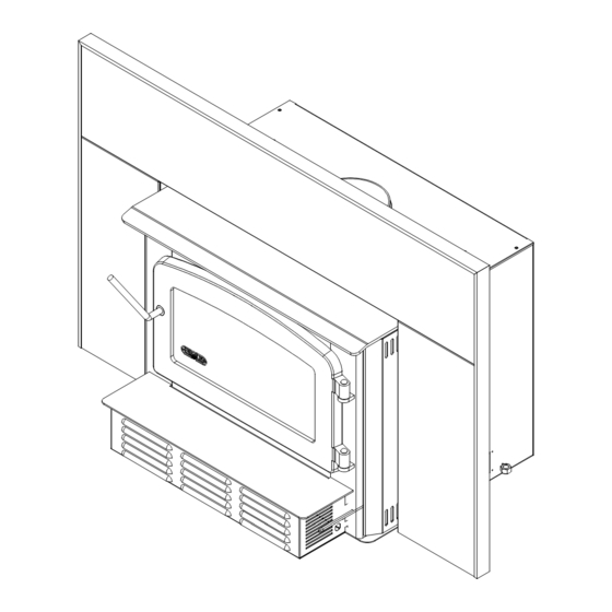
4.4 Baffle Installation for Escape 1400-I ................... 23 4.5 Secondary Air Tube Replacement ....................24 4.6 Fan Maintenance & Care ......................25 4.7 Removal instructions ........................25 Section 5.0 Specifications ............... 26 5.1 Escape 1400-I Insert Model......................26 DROLET LIMITED LIFETIME WARRANTY ......27... - Page 4 Escape 1400-I Dimensions Faceplate fully extended toward the back Faceplate fully extended toward the front...
-
Page 5: Section 1.0 Pre-Installation Requirements
Section 1.0 Pre-Installation Requirements 1.1 Masonry & Zero Clearance Requirements The masonry fireplace must meet the minimum code requirements, or NFPA 211 or the equivalent for a safe installation. Contact your local Building Inspector for requirements in your area. An inspection of the fireplace should include the following: 1. -
Page 6: Venting Requirements
1.2 Venting Requirements The flue is a critical component to a satisfactory installation. Your insert will attain its best performance if installed with a flue that generates its own draft. The minimum venting requirement will be the installation of a flue connector from the insert into the first tile of the chimney (see Figure 2.3). If you are using a masonry chimney, it is important that it be built in compliance with the specifications of the National Building Code or other applicable standard having jurisdiction. -
Page 7: Section 2.0 Installation
Section 2.0 Installation 2.1 Minimum masonry opening, clearances to combustibles, and floor protector... - Page 8 MINIMUM MASONRY OPENING 21 3/8” (543 mm)* 28 7/8” (733 mm) 12 3/4” (324 mm)* CLEARANCES 13” (335 mm) 10” (255 mm) 22” (560 mm) 29” (740 mm) FLOOR PROTECTOR CANADA 18’’ (460 mm) – Note1 16’’ (410 mm) – Note 1 8’’...
-
Page 9: Safety Information
Floor protection to the front is to be measured from the fuel loading door opening. 5. Drolet recommends that you install a listed smoke detector or alarm in your home. Normal operation of the insert will have no effect on the detector or alarm. -
Page 10: Installation Instructions
2.3 Installation Instructions 1. Inspect the fireplace according to the safety information and fireplace requirements and Inspect the fireplace according to the safety information and fireplace requirements and Inspect the fireplace according to the safety information and fireplace requirements and have it cleaned and/or upgraded as necessary. -
Page 11: Faceplate And Decorative Trims Installation Instructions (Sold Separately)
4. If lag-bolts and anchors are to be used to secure the insert, the hole locations should be marked with the unit in place. Remove the insert and locate the anchors. 5. Remove the faceplate panels from their box and assemble according to the following instructions. - Page 12 Insert the superimposed brackets (G) and (H) with the screws (F) in the groove of each decorative trim (I), (J) and (K) (see DETAIL B). Align the corners of the angled side of each trim, and then tighten the screws (F) to secure the trims.
- Page 13 Then align the holes in the faceplate extension (N) with the holes in each faceplate side panels and secure both assembly together using four (4) bolts (D) and nuts (E) provided (see DETAIL C) . Center the insert into the fireplace opening bring faceplate...
-
Page 14: Blower Installation Instructions
Align the notch in the faceplate extension with the bolt (O) welded to the air jacket located (see DETAIL D) and slide the faceplate assembly just over the washer (P) and bolt’s head (Q). Then push towards the fireplace. If necessary, adjust the height of the insert using the leveling bolts on each side of the convection air jacket until the faceplate is properly seated on the... -
Page 15: Installation Of The Fresh Air Intake Kit Ac01298 (Sold Separately)
2.6 Installation of the fresh air intake kit AC01298 (sold separately) In order to avoid some combustion problems, it is highly recommended to install a fresh air intake kit. To do so, you need to have the accessory #AC01298. Using pliers, remove the metal rectangle (A) located on the side of the insert. -
Page 16: Section 3.0 Operation
Do not abuse the unit, either by over firing or by using wood or combustibles with salt content, or harmful chemicals. Misuse is not covered by warranty. Even though your Drolet insert has been specifically designed and tested to prevent smoke spillage, always open the door slowly as this will minimize the likelihood of smoke spillage or a back draft causing flame or smoke to spill into the room. -
Page 17: Fuel
3.2 Fuel Fuel for the insert must not be stored closer than the required clearances to combustibles and not in the space required for ash removal. Your Drolet insert is designed to burn . Do not burn coal, charcoal, or ORDWOOD trash in the unit. -
Page 18: Simple Wood Moisture Test
Common Heating Values of Cordwood Hardwoods Million Btu/Cord Softwoods Million Btu/Cord Birch 23.6 Douglas Fir 20.6 White Oak 28.3 Hemlock 17.1 Alder 17.6 Jack Pine 18.4 Table 3.1 3.2.1 Simple Wood Moisture Test Add one large piece of wood to the top of an established fire. If it starts to burn on three sides within one minute, it is dry and seasoned and right for burning. -
Page 19: Lighting A Fire
3.4 Lighting A Fire Place enough crumpled balls of newspaper or other paper into the insert to cover the bottom of the firebox. Place small dry kindling on the crumpled paper. Place larger dry kindling on top of the small kindling. Open the draft control fully to the right (located on the right side of the faceplate, Figure 3.1) Light a fire at the bottom of the crumpled paper and close the door. -
Page 20: Maintaining The Fire
3.5 Maintaining The Fire Your Drolet insert will work best if a thick bed of hot embers is maintained in the bottom of the firebox and a minimum of two large pieces of seasoned fuel are added. Combustion efficiency is largely related to establishing a hot ember bed, and hot firebox temperatures. -
Page 21: Section 4.0 Maintenance
Section 4.0 Maintenance 4.1 Care And Cleaning Clean the insert frequently so that soot, ash and creosote do not accumulate. Do not attempt to clean the insert, glass or door when the unit is hot. Special care must be taken with plated surfaces in order to maintain the finish at its original brilliance. -
Page 22: Ash Removal
Drolet dealer. Your Drolet insert has been designed to reduce the amount of creosote produced. Even so, the chimney connector pipe and chimney should be inspected at least once every two months during the heating season to determine if a creosote build-up has occurred. -
Page 23: Baffle Installation For Escape 1400-I
4.4 Baffle Installation for Escape 1400-I WOOL WEIGHT INSULATION BLANKET VERMICULITE BAFFLE BOARD MIDDLE AND REAR TUBES FRONT TUBE FRONT BAFFLE SUPPORT Figure 4.1 – Baffle installation & removal for Escape 1400-I The baffle assembly must be properly in place for correct burning operation. Have any damaged firebricks replaced. -
Page 24: Secondary Air Tube Replacement
4.5 Secondary Air Tube Replacement (see Figure 4.3) Remove cotter pin at RH end of tube. Slide tube to left and lower tube end below RH plenum. Slide tube to right to remove. Reassemble in reverse order using a new cotter pin. The cotter pin is a hammerlock style and locks into place by hitting the head sharply with a hammer. -
Page 25: Fan Maintenance & Care
4.6 Fan Maintenance & Care Clean the fan air inlet louvres and squirrel cage impeller regularly. The fan should be kept clean and dust free. Life of the fan will be shortened if operated in a dust filled environment, or if the fan is overheated by restricting air supply. -
Page 26: Section 5.0 Specifications
Section 5.0 Specifications 5.1 Escape 1400-I Insert Model Fuel Type Cordwood Test Standards ULC S628 (CSA B366.2) & UL 1482 residential. Recommended surface: 700 to 1600 sq. ft. Heating capacity* – BTU/hr., EPA test wood: 39,000 BTU/h. Heating capacity* – BTU/hr., seasoned cordwood: 60,000 BTU/h. -
Page 27: Drolet Limited Lifetime Warranty
Firebrick *Pictures required Shall your unit or a components be defective, contact immediately your DROLET dealer. Prior to your call make sure you have the following information necessary to your warranty claim treatment: •...