Asus P4S800-MX SE User Manual
Asus motherboard user guide
Hide thumbs
Also See for P4S800-MX SE:
- User manual (64 pages) ,
- Manuel (64 pages) ,
- Guide utilisateur (88 pages)
Table of Contents
Advertisement
Quick Links
Advertisement
Table of Contents

Related Manuals for Asus P4S800-MX SE


Summary of Contents for Asus P4S800-MX SE
- Page 1 P4S800-MX SE User Guide...
- Page 2 Product warranty or service will not be extended if: (1) the product is repaired, modified or altered, unless such repair, modification of alteration is authorized in writing by ASUS; or (2) the serial number of the product is defaced or missing.
-
Page 3: Table Of Contents
Contents Notices ... v Safety information ... vi P4S800-MX SE specification summary ... viii About this guide ... ix Chapter 1: Product introduction 1.1 Welcome! ... 1-2 1.2 Package contents ... 1-2 1.3 Special features ... 1-2 1.4 Before you proceed ... 1-5 1.5 Motherboard overview ... - Page 4 Using AFUDOS to copy the current BIOS ... 2-3 2.1.3 Using AFUDOS to update the BIOS ... 2-4 2.1.4 Using ASUS EZ Flash to update the BIOS ... 2-5 2.1.5 ASUS CrashFree BIOS 2 utility ... 2-6 2.1.6 ASUS Update utility ... 2-8 2.2 BIOS Setup program ...
- Page 5 Running the support CD ... 3-2 3.2.2 Drivers menu ... 3-3 3.2.3 Utilities menu ... 3-3 3.2.4 ASUS contact information ... 3-4 3.3 RAID configurations ... 3-5 3.3.1 Installing hard disks ... 3-5 3.3.2 SIS RAID configurations ... 3-6 3.4 Creating a RAID driver disk ... 3-15...
-
Page 6: Notices
Notices Federal Communications Commission Statement This device complies with Part 15 of the FCC Rules. Operation is subject to the following two conditions: • This device may not cause harmful interference, and • This device must accept any interference received including interference that may cause undesired operation. -
Page 7: Safety Information
Safety information Electrical safety • To prevent electrical shock hazard, disconnect the power cable from the electrical outlet before relocating the system. • When adding or removing devices to or from the system, ensure that the power cables for the devices are unplugged before the signal cables are connected. -
Page 8: P4S800-Mx Se Specification Summary
P4S800-MX SE specification summary Chipset Front Side Bus (FSB) Memory Expansion slots Storage Audio Special features Overclock Features Rear panel I/O Internal I/O viii Socket 478 for Intel ® Pentium ® ® Intel Hyper-Threading technology ready ® Supports Intel Prescott CPU... -
Page 9: About This Guide
P4S800-MX SE specification summary BIOS features 4Mb Flash ROM, AMI BIOS, PnP features, DMI2.0, WfM2.0, SM BIOS 2.3, ACPI 2.0, ASUS CrashFree BIOS 2, ASUS MyLogo2, ASUS C.P.R. (CPU Parameter Recall), ASUS EZ Flash Industry standard PCI 2.2, USB 2.0/1.1 Manageability WOL/WOR by PME, WfM 2.0, DMI 2.0... -
Page 11: Chapter 1: Product Introduction
Chapter 1 This chapter describes the features of the motherboard. It includes brief descriptions of the motherboard components, and illustrations of the layout, jumper settings, and connectors. Product introduction... -
Page 12: Welcome
Welcome! Thank you for buying the ASUS The ASUS P4S800-MX SE motherboard delivers a host of new features and latest technologies making it another standout in the long line of ASUS quality motherboards! Before you start installing the motherboard, and hardware devices on it, check the items in your package with the list below. - Page 13 The motherboard supports the Serial ATA technology through the Serial ATA interfaces and the SIS 964 chipset. The SATA specification allows for thinner, more flexible cables with lower pin count, reduced voltage requirement, and up to 150 MB/s data transfer rate. See page 1-19 for details. ASUS P4S800-MX SE motherboard...
-
Page 14: Asus Crashfree Bios
ROM chip. See details on page 2-6. ASUS EZ Flash BIOS With the ASUS EZ Flash, you can easily update the system BIOS even before loading the operating system. No need to use a DOS-based utility or boot from a floppy disk. -
Page 15: Before You Proceed
Onboard LED The P4S800-MX SE comes with a stand-by power LED. When lit, the green LED indicates that the system is ON, in sleep mode, or in soft-off mode, a reminder that you should shut down the system and unplug the power cable before removing or plugging in any motherboard component. -
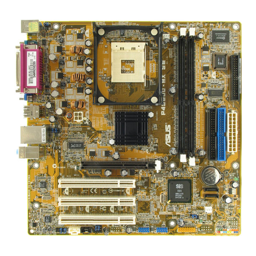
Page 16: Motherboard Overview
Motherboard overview 1.5.1 Motherboard layout KBPWR PS/2KBMS T: Mouse B: Keyboard COM1 USB12 ATX12V USB34 RJ-45 USBPW34 USBPW12 Top:Line In Center:Line Out Below:Mic In RTL8201CL ALC655 FP_AUDIO KBPWR USBPW34 USBPW12 +5VSB (Default) (Default) 24.5cm (9.6in) CPU_FAN1 Socket 478 661FX North Bridge PCI1 PCI2 PCI3... -
Page 17: Placement Direction
Place eight (8) screws into the holes indicated by circles to secure the motherboard to the chassis. Do not overtighten the screws! Doing so may damage the motherboard. Place this side towards the rear of the chassis ASUS P4S800-MX SE motherboard... -
Page 18: Central Processing Unit (Cpu)
4 processor has a gold triangular mark on one corner. This mark indicates the processor Pin 1 that should match a specific corner of the CPU socket. P4S800-MX SE CPU Socket 478 Incorrect installation of the CPU into the socket may bend the pins and severely damage the CPU! ®... -
Page 19: Installing The Cpu
6. Install a CPU heatsink and fan following the instructions that came with the heatsink package. 7. Connect the CPU fan cable to the CPU_FAN1 connector on the motherboard. ASUS P4S800-MX SE motherboard Socket Lever Gold Mark 90 - 100... -
Page 20: System Memory
You may install 64MB, 128MB, 256MB, 512MB, and 1GB DDR DIMMs into the DIMM sockets. Obtain DDR DIMMs only from ASUS qualified vendors. Refer to the Qualified DDR400 vendors list next page. Visit the ASUS website (www.asus.com) for the latest DDR Qualified Vendors List. - Page 21 77.10636.11G APACER 77.10736.11G BRAIN POWERN/A KINGMAX KINGMAX MPXC22D-38KT3R NANYA NT512D64S8HB1G-5T PROMOS V826632K24SCTG-D0 * Side/s: DS - Double-sided SS - Single-sided ASUS P4S800-MX SE motherboard Brand Side(s) Component VS32M8-5 2B0409 VS32M8-5 2B0412 HYNIX HY5DU56822BT-D43 HYNIX HY5DU56822DT-D43 INFINEON HYB25D256800CE-5-C INFINEON HYB25D256800CE-5C HYB25D256800BT-5B...
-
Page 22: Installing A Dimm
1.7.3 Installing a DIMM Follow these steps to install a DIMM. 1. Unlock a DIMM socket by pressing the retaining clips outward. 2. Align a DIMM on the socket such that the notch on the DIMM matches the break on the socket. 3. -
Page 23: Configuring An Expansion Card
When using PCI cards on shared slots, ensure that the drivers support “Share IRQ” or that the cards do not need IRQ assignments. Otherwise, conflicts will arise between the two PCI groups, making the system unstable and the card inoperable. ASUS P4S800-MX SE motherboard Standard Function System Timer Keyboard Controller... -
Page 24: Pci Slots
Note the notches on the card golden fingers to ensure that they fit the AGP slot on the motherboard. This motherboard does not support 3.3V AGP cards. Install only +1.5V AGP cards. P4S800-MX SE Accelerated Graphics Port (AGP) 1-14 Keyed for 1.5v Chapter 1: Product introduction... -
Page 25: Jumpers
4. Hold down the <Del> key during the boot process and enter BIOS setup to re-enter data. Except when clearing the RTC RAM, never remove the cap on CLRTC1 jumper default position. Removing the cap will cause system boot failure! P4S800-MX SE Clear RTC RAM ASUS P4S800-MX SE motherboard CLRTC1 Clear CMOS... - Page 26 2. The total current consumed must NOT exceed the power supply capability (+5VSB) whether under normal condition or in sleep mode. P4S800-MX SE USB device wake up 3. Keyboard power (3-pin KBPWR1) This jumper allows you to enable or disable the keyboard wake-up feature. Set this jumper to pins 2-3 (+5VSB) if you wish to wake up the computer when you press a key on the keyboard (the default is the Space Bar).
-
Page 27: Connectors
9. VGA port. This port connects a VGA compatible monitor. 10. Serial port. This 9-pin COM port is for pointing devices or other serial devices. 11. PS/2 keyboard port. This purple connector is for a PS/2 keyboard. ASUS P4S800-MX SE motherboard 4-Speaker Rear Speaker Out... -
Page 28: Internal Connectors
(Pin 5 is removed to prevent incorrect insertion when using ribbon cables with pin 5 plug). P4S800-MX SE Floppy disk drive connector 1-18 NOTE: Orient the red markings (usually zigzag) on the IDE ribbon cable to PIN 1. - Page 29 150 MB/s data transfer rate, faster than the standard parallel ATA with 133MB/s (Ultra ATA/133). P4S800-MX SE SATA connectors If you install SATA hard disk drives, you can create a RAID 0, RAID 1, or JBOD configuration with the SIS964 RAID controller. Refer to page 2-16 for the BIOS setting and page 3-15 for creating a RAID driver disk.
- Page 30 1A on the +5-volt standby lead (+5VSB). The minimum recommended wattage is 230W, or 300W for a fully configured system. The system may become unstable and may experience difficulty powering up if the power supply is inadequate. P4S800-MX SE ATX power connectors 1-20 ATX12V ATXPWR +12.0VDC...
- Page 31 LINE OUT_L/BLINE_OUT_L are shorted with jumper caps. Remove the caps only when you are connecting the front panel audio cable. P4S800-MX SE Front panel audio connector 6. CPU fan connector (3-pin CPU_FAN1) The CPU fan connector support cooling fans of 350mA~740mA (8.88W max.) or a total of 1A~2.22A (26.64W max.) at +12V.
- Page 32 The module has two USB 2.0 ports for connecting next generation USB peripherals such as high resolution cameras, scanners, and printers. P4S800-MX SE USB 2.0 connectors The USB module is purchased separately. 8. Digital audio connector (4-1 pin SPDIF) An onboard S/PDIF Out connector is available for an optional S/PDIF audio module.
- Page 33 These connectors allow you to receive stereo audio input from sound sources such as a CD-ROM, TV tuner, or MPEG card. P4S800-MX SE Internal audio connectors 10. GAME/MIDI connector (16-1 pin GAME1) This connector supports a GAME/MIDI module. Connect the GAME/MIDI cable with yellow connector to the yellow header onboard.
-
Page 34: System Panel Connector
11. System panel connector (20-pin PANEL) This connector accommodates several system front panel functions. P4S800-MX SE System panel connector The system panel connector is color-coded for easy connection. Refer to the connector description below for details. • System power LED (Green 3-pin PLED) This 3-pin connector is for the system power LED. -
Page 35: Chapter 2: Bios Information
Chapter 2 This chapter tells how to change system settings through the BIOS Setup menus. Detailed descriptions of the BIOS parameters are also provided. BIOS information... -
Page 36: Managing And Updating Your Bios
BIOS file in a floppy disk. • Visit the ASUS website and download the latest BIOS file for this motherboard using the ASUS Update utility. 2.1.1 Creating a bootable floppy disk 1. -
Page 37: Using Afudos To Copy The Current Bios
A:\>afudos /oMYBIOS03.rom AMI Firmware Update Utility - Version 1.10 Copyright (C) 2002 American Megatrends, Inc. All rights reserved. Reading flash ... done A:\> When the BIOS copy process is complete, the utility returns to the DOS prompt. ASUS P4S800-MX SE motherboard... -
Page 38: Using Afudos To Update The Bios
To update the BIOS using the AFUDOS.EXE: 1. Visit the ASUS website (www.asus.com) to download the latest BIOS file for your motherboard. Save the BIOS file to a bootable floppy disk. Write down the BIOS file name to a piece of paper. You need to type the exact BIOS file name at the prompt. -
Page 39: Using Asus Ez Flash To Update The Bios
2.1.4 Using ASUS EZ Flash to update the BIOS The ASUS EZ Flash feature allows you to easily update the BIOS without having to go through the long process of booting from a floppy disk and using a DOS-based utility. The EZ Flash is built-in the BIOS LPC chip so it is accessible by simply pressing <Alt>... -
Page 40: Asus Crashfree Bios 2 Utility
2.1.5 ASUS CrashFree BIOS 2 utility The ASUS CrashFree BIOS 2 is an auto recovery tool that allows you to restore the BIOS file when it fails or gets corrupted during the updating process. You can update a corrupted BIOS file using the motherboard support CD or the floppy disk that contains the updated BIOS file. - Page 41 4. Restart the system after the utility completes the updating process. The recovered BIOS may not be the latest BIOS version for this motherboard. Visit the ASUS website (www.asus.com) to download the latest BIOS file. ASUS P4S800-MX SE motherboard...
-
Page 42: Asus Update Utility
2.1.6 ASUS Update utility The ASUS Update is a utility that allows you to manage, save, and update the motherboard BIOS in Windows • Save the current BIOS file • Download the latest BIOS file from the Internet • Update the BIOS from an updated BIOS file •... - Page 43 Updating the BIOS through the Internet To update the BIOS through the Internet: 1. Launch the ASUS Update utility from the Windows Programs > ASUS > ASUSUpdate > ASUSUpdate. The ASUS Update main window appears. 2. Select Update BIOS from the Internet option from the drop-down menu, then click Next.
- Page 44 Updating the BIOS through a BIOS file To update the BIOS through a BIOS file: 1. Launch the ASUS Update utility from the Windows Programs > ASUS > ASUSUpdate > ASUSUpdate. The ASUS Update main window appears. 2. Select Update BIOS from a file option from the drop-down menu, then click Next.
-
Page 45: Bios Setup Program
Because the BIOS software is constantly being updated, the following BIOS setup screens and descriptions are for reference purposes only, and may not exactly match what you see on your screen. ASUS P4S800-MX SE motherboard 2-11... -
Page 46: Bios Menu Screen
Some of the navigation keys differ from one screen to another. 2-12 Configuration fields [11:51:19] [Thu 08/05/2003] [1.44M, 3.5 in] : [ST320413A] : [ASUS CD-S340] : [Not Detected] : [Not Detected] [RAID Mode] Chapter 2: BIOS information General help Use [ENTER], [TAB] or [SHIFT-TAB] to select a field. -
Page 47: Menu Items
2.2.9 General help At the top right corner of the menu screen is a brief description of the selected item. ASUS P4S800-MX SE motherboard System Time [11:51:19] Use [ENTER], [TAB] System Date... -
Page 48: Main Menu
Use [ENTER], [TAB] [11:51:19] or [SHIFT-TAB] to [Thu 08/05/2003] select a field. [1.44M, 3.5 in] Use [+] or [-] to configure system time. : [ST320413A] : [ASUS CD-S340] : [Not Detected] : [Not Detected] [RAID Mode] Chapter 2: BIOS information... -
Page 49: Primary And Secondary Ide Master/Slave
Configuration options: [Disabled] [Auto] PIO Mode [Auto] Selects the PIO mode. Configuration options: [Auto] [0] [1] [2] [3] [4] ASUS P4S800-MX SE motherboard Select the type of device connected to the system... -
Page 50: Onchip Sata Controller
DMA Mode [Auto] Selects the DMA mode. Configuration options: [Auto] [SWDMA0] [SWDMA1] [SWDMA2] [MWDMA0] [MWDMA1] [MWDMA2] [UDMA0] [UDMA1] [UDMA2] [UDMA3] [UDMA4] [UDMA5] [UDMA6] SMART Monitoring [Auto] Sets the Smart Monitoring, Analysis, and Reporting Technology. Configuration options: [Auto] [Disabled] [Enabled] 32Bit Data Transfer [Disabled] Enables or disables 32-bit data transfer. -
Page 51: Advanced Menu
If this happens, revert to the default setting. If you are using an unlocked CPU, the item CPU Ratio appears under the AI Overclock Tuner item. You may select your desired ratio from the available options. ASUS P4S800-MX SE motherboard [Standard] [Enabled] [Auto]... - Page 52 CPU Frequency (Value auto-detected) Indicates the frequency sent by the clock generator to the system bus and PCI bus. The bus frequency (external frequency) multiplied by the bus multiple equals the CPU speed. The value of this item is auto-detected by BIOS and ranges from 100 to 400.
-
Page 53: Cpu Configuration
Hyper-Threading Technology [Enabled] Allows you to enable or disable the processor Hyper-Threading Technology. This item appears only when you installed a CPU with Hyper-Threading Technology feature. Configuration options: [Disabled] [Enabled] ASUS P4S800-MX SE motherboard Enable or Disable Update CPU MicroCode [Disabled]... -
Page 54: Chipset
2.4.3 Chipset The Chipset menu items allow you to change the advanced chipset settings. Select an item then press Enter to display the sub-menu. NorthBridge SIS661FX Configuration SouthBridge SIS964 Configuration NorthBridge SiS661FX Configuration Primary Graphics Adapter MA 1T/2T Select DRAM CAS# Latency DRAM Precharge Delay DRAM RAS# to CAS# Delay DRAM RAS# Precharge... - Page 55 OnBoard LAN Boot ROM [Disabled] Allows you to enable or disable the option ROM in the onboard LAN controller. This item appears only when the Onboard LAN item is set to Enabled. Configuration options: [Disabled] [Enabled] ASUS P4S800-MX SE motherboard [Enabled] [Enabled] [Disabled]...
-
Page 56: Onboard Devices Configuration
2.4.4 Onboard Devices Configuration Configure onboard device Serial Port1 Address Parallel Port Address Parallel Port Mode ECP Mode DMA Channel Parallel Port IRQ Onboard Game/MIDI Port Serial Port1 Address [3F8/IRQ4] Allows you to select the Serial Port1 base address. Configuration options: [Disabled] [3F8/IRQ4] [2F8/IRQ3] [3E8/IRQ4] [2E8/IRQ3] Parallel Port Address [378] Allows you to select the Parallel Port base addresses. -
Page 57: Pci Pnp
ISA graphics device is installed in the system so that the latter can function correctly. Setting to [Disabled] deactivates this feature. Configuration options: [Disabled] [Enabled] ASUS P4S800-MX SE motherboard NO: Lets the BIOS configure all the devices in the system. -
Page 58: Usb Configuration
2.4.6 USB Configuration The items in this menu allows you to change the USB-related features. Select an item then press Enter to display the configuration options. OnBoard SiS USB1.1 Device OnBoard SiS USB2.0 Device USB Configuration Module Version - 2.23.2-10.4 USB Devices Enabled: None Legacy USB Support USB 2.0 Controller Mode... -
Page 59: Power Menu
Allows you to enable or disable the ACPI (Advanced Configuration and Power Interface) support in the ASIC (Application Specific Integrated Circuit). When set to Enabled, the ACPI APIC table pointer is included in the RSDT pointer list. Configuration options: [Disabled] [Enabled] ASUS P4S800-MX SE motherboard Enable/Disable [Auto] ACPI support for [No] Operating System. -
Page 60: Apm Configuration
2.5.4 APM Configuration Power Button Mode Restore on AC Power Loss Power On By PS2 Keyboard Power On By PS2 Mouse Power On By Internal MAC LAN Power On By PCI Devices Power On By External Modems Power On By RTC Alarm Power Button Mode [On/Off] Allows the system to go into On/Off mode or suspend mode when the power button is pressed. -
Page 61: Hardware Monitor
N/A. VCORE Voltage, +3.3V Voltage, +5V Voltage, +12V Voltage The onboard hardware monitor automatically detects the voltage output through the onboard voltage regulators. ASUS P4S800-MX SE motherboard CPU Temperature [65.5ºC/148ºF] [36ºC/96.5ºF] [3260RPM] [N/A] [ 1.504V]... -
Page 62: Boot Menu
[First Floppy Drive] available devices. [PM-ST320413A] [PS-ASUS CD-S340] A device enclosed in Specifies the boot sequence from the [1st FLOPPY DRIVE] available devices. [ASUS USB Flash Disk] [ASUS USB Flash Disk] A device enclosed in Chapter 2: BIOS information... -
Page 63: Boot Settings Configuration
POST. Configuration options: [Disabled] [Enabled] Interrupt 19 Capture [Disabled] When set to [Enabled], this function allows the option ROMs to trap Interrupt 19. Configuration options: [Disabled] [Enabled] ASUS P4S800-MX SE motherboard Allows BIOS to skip certain tests while [Enabled] booting. -
Page 64: Security
2.6.4 Security The Security menu items allow you to change the system security settings. Select an item then press Enter to display the configuration options. Security Settings Supervisor Password User Password Change Supervisor Password Change User Password Clear User Password Password Check Change Supervisor Password Select this item to set or change the supervisor password. - Page 65 When set to [Setup], BIOS checks for user password when accessing the Setup utility. When set to [Always], BIOS checks for user password both when accessing Setup and booting the system. Configuration options: [Setup] [Always] ASUS P4S800-MX SE motherboard 2-31...
-
Page 66: Exit Menu
Exit menu The Exit menu items allow you to load the optimal or failsafe default values for the BIOS items, and save or discard your changes to the BIOS items. Exit Options Exit & Save Changes Exit & Discard Changes Discard Changes Load Setup Defaults Pressing <Esc>... -
Page 67: Software Support
Chapter 3 This chapter describes the contents of the support CD that comes with the motherboard package. Software support... -
Page 68: Chapter 3: Software Support
The contents of the support CD are subject to change at any time without notice. Visit the ASUS website for updates. 3.2.1 Running the support CD To begin using the support CD, simply insert the CD into your CD-ROM drive. The CD automatically displays the Drivers menu if Autorun is enabled in your computer. -
Page 69: Drivers Menu
Installs the driver for the onboard SiS PCI LAN controller. USB 2.0 Driver Installs the Universal Serial Bus 2.0 (USB 2.0) driver. 3.2.3 Utilities menu The Utilities menu shows the applications and other software that the motherboard supports. ASUS P4S800-MX SE motherboard... -
Page 70: Asus Contact Information
ASUS Update This program allows you to download the latest version of the BIOS from the ASUS website. Before using the ASUS Update, make sure that you have an Internet connection so you can connect to the ASUS website. -
Page 71: Raid Configurations
To install the SATA hard disks for a RAID configuration: 1. Install the SATA hard disks into the drive bays. 2. Connect the SATA signal cables. 3. Connect a SATA power cable to the power connector on each drive. ASUS P4S800-MX SE motherboard... -
Page 72: Sis Raid Configurations
3.3.2 SIS RAID configurations The motherboard includes a high performance Serial ATA RAID controller integrated in the SIS 964 southbridge chipset. It supports RAID 0 and RAID 1 with two independent Serial ATA channels. Entering the SIS RAID BIOS utility 1. -
Page 73: Creating Jbod
2. Select <1> to auto-create a RAID array or press <2> to manually configure array then press <Enter>. 3. If you selected 1 proceed to step 5. 4. Use the up/down arrow keys to move the selection bar, then press <Enter> to select a disk drive. ASUS P4S800-MX SE motherboard... - Page 74 5. The current RAID set is displayed on the upper side of the screen. 6. Press <Q> to exit the RAID setup. 7. Press <Y> then <Enter> to save changes. After the setup is complete, you can partition and format your hard disk as a single hard drive.
- Page 75 <Enter>. 3. If you selected 1 proceed to step 7. 4. If you selected 2, select the array block size by pressing the corresponding number beside the available block sizes then press <Enter>. ASUS P4S800-MX SE motherboard...
- Page 76 5. Use the up/down arrow keys to move the selection bar, then press <Enter> to select a disk drive. 6. After selecting the drives, press <Q> to return to previous menu. 7. Press <N> then <Enter> to create a Stripe only configuration. Press <Y> if you wish to split the data on the source disk to other disks.
- Page 77 10. The current RAID setup is displayed on the upper side of the screen. Press <Q> to exit the RAID setup menu. 11. Press <Y> then <Enter> to save changes. 12. When finished, you can partition and format the array as a single hard drive. ASUS P4S800-MX SE motherboard 3-11...
- Page 78 Creating RAID 1 for capacity 1. From the RAID Setup, press <3> then <Enter> to select RAID 1 (Mirroring). 2. Select <1> to auto-create a RAID array or press <2> to manually configure array then press <Enter>. 3. If you selected 1 proceed to step 5. 4.
- Page 79 (DISK 1) data to the RAID disks. 6. If you selected Y, the followig screen appears. 7. When finished, press <Q> to return to previous menu. The current RAID set is displayed on the upper side of the screen. ASUS P4S800-MX SE motherboard 3-13...
- Page 80 8. Press <Q> to exit the RAID setup. 9. Press <Y> then <Enter> to save changes. 10. After the setup is complete, you can partition and format the array as a single hard drive. 3-14 Chapter 3: Software support...
-
Page 81: Creating A Raid Driver Disk
1. During the OS installation, the system prompts you to press the <F6> key to install third-party SCSI or RAID driver. 2. Press <F6> then insert the floppy disk with RAID driver into the floppy disk drive. 3. Follow the succeeding screen instructions to complete the installation. ASUS P4S800-MX SE motherboard ® 2000/XP 3-15... - Page 82 3-16 Chapter 3: Software support...
- Page 83 ASUS P4S800-MX SE motherboard 3-17...
- Page 84 3-18 Chapter 3: Software support...