Asus Motherboard M3A78-EM User Manual
Asus motherboard user guide
Hide thumbs
Also See for Motherboard M3A78-EM:
- Qualified vendor list (5 pages) ,
- User manual (8 pages) ,
- User manual (44 pages)
Table of Contents
Advertisement
Advertisement
Table of Contents

Related Manuals for Asus Motherboard M3A78-EM


Summary of Contents for Asus Motherboard M3A78-EM
- Page 1 M3A78-EM...
- Page 2 Product warranty or service will not be extended if: (1) the product is repaired, modified or altered, unless such repair, modification of alteration is authorized in writing by ASUS; or (2) the serial number of the product is defaced or missing.
-
Page 3: Table Of Contents
Special.features..1-2 1.3.1 Product highlights ... 1-2 1.3.2 ASUS unique features ... 1-6 1.3.3 ASUS stylish features ... 1-8 1.3.4 ASUS intelligent overclocking features ... 1-8 1.4. Before.you.proceed... 1-9 1.5. Motherboard.overview..1-10 1.5.1 Motherboard layout ... 1-10 1.5.2 Placement direction ...1-11... - Page 4 Managing.and.updating.your.BIOS... 2-2 2.1.1 Creating a bootable floppy disk ... 2-2 2.1.2 AFUDOS utility ... 2-3 2.1.3 ASUS CrashFree BIOS 3 utility ... 2-6 2.1.4 ASUS EZ Flash 2 utility ... 2-8 2.1.5 ASUS Update utility ... 2-9 2.2. BIOS.setup.program... 2-12 2.2.1...
- Page 5 Boot Device Priority ... 2-34 2.6.2 Boot Settings Configuration ... 2-34 2.6.3 Security ... 2-36 2.7. Tools.menu... 2-38 2.7.1 ASUS EZ Flash 2 ... 2-38 2.7.2 Express Gate ... 2-39 2.7.3 AI NET 2... 2-39 2.8. Exit.menu... 2-40 Chapter.3:. Software.support 3.1.
-
Page 6: Notices
Notices Federal.Communications.Commission.Statement This device complies with Part 15 of the FCC Rules. Operation is subject to the following two conditions: • This device may not cause harmful interference, and • This device must accept any interference received including interference that may cause undesired operation. -
Page 7: Safety.information
Safety information Electrical.safety • To prevent electrical shock hazard, disconnect the power cable from the electrical outlet before relocating the system. • When adding or removing devices to or from the system, ensure that the power cables for the devices are unplugged before the signal cables are connected. If possible, disconnect all power cables from the existing system before you add a device. -
Page 8: About.this.guide
Refer to the following sources for additional information and for product and software updates. ASUS.websites The ASUS website provides updated information on ASUS hardware and software products. Refer to the ASUS contact information. Optional.documentation Your product package may include optional documentation, such as warranty flyers, that may have been added by your dealer. - Page 9 Conventions.used.in.this.guide To make sure that you perform certain tasks properly, take note of the following symbols used throughout this manual. DANGER/WARNING: Information to prevent injury to yourself when trying to complete a task. CAUTION: Information to prevent damage to the components when trying to complete a task.
-
Page 10: M3A78-Em Specifications Summary
* Due to AMD CPU limitation, DDR2 1066 is supported by AM2+ CPU for one DIMM per channel only. ** Refer to www.asus.com or user manual for Memory QVL (Qualified Vendors List) *** When you install a total memory of 4GB or more, Windows®... - Page 11 1 x ESATA port 1 x DisplayPort 1 x RJ45 port 6 x USB 2.0/1.1 ports 8-channel Audio I/O ports 8Mb Flash ROM, AMI BIOS, PnP, DMI2.0, WfM2.0, SM BIOS 2.5, ACPI2.0a, ASUS EZ Flash 2 (continued on the next page)
- Page 12 2 x Serial ATA power cables 1 x UltraDMA 133/100/66 cable 1 x FDD cable 2 in 1 Q-Connector uATX Form factor: 9.6’’ x 9.6’’ (24.4cm x 24.4cm) Drivers Express Gate ASUS PC Probe II ASUS LiveUpdate Utility Anti-Virus software (OEM version)
- Page 13 This chapter describes the motherboard features and the new technologies it supports. Product introduction...
-
Page 14: Chapter 1: Product Introduction
Green.ASUS. This motherboard and its packaging comply with the European Union’s Restriction on the use of Hazardous Substances (RoHS). This is in line with the ASUS vision of creating environment-friendly and recyclable products/packaging to safeguard consumers’ health while minimizing the impact on the environment. - Page 15 HDCP compliant ,and incorporates AMD’s UVD with hardware acceleration of H.264, VC1 and Mpeg2 used in HD DVD and BluRay disks. Meanwhile it can also support the future mainstream Hybrid CrossFire Technology that significantly optimizes your 3D performance. ASUS M3A78-EM Socket AM2+ multi-core processors with ®...
- Page 16 • Hybrid CrossFireX technology is supported by Windows Vista • Refer to www.asus.com for the discrete graphics GPU QVL which lists the GPUs that support the Hybrid CrossFireX technology. PCI.Express.2.0.support. This motherboard supports the latest PCIe 2.0 devices for double speed and bandwidth which enhances system performance.
- Page 17 DisplayPort. This new design features a small and user-friendly connector. It delivers higher performances of resolution, refresh rate, and color depth and improves digital display connectivity. Due to chipset limitation, DisplayPort on this motherboard only supports video signals. ASUS M3A78-EM SB700 allows RAID 0, RAID ®...
-
Page 18: Asus Unique Features
• Due to chipset limitation, ASUS Express Gate supports USB devices or SATA HDDs (IDE mode) connected to SATA port 1-4 only. Set the OnChip. SATA.Type item in the BIOS to [SATA] before installing and using ASUS Express Gate. •... - Page 19 To wake the system and return to the OS environment, simply click the mouse or press a key. ASUS.EZ.DIY ASUS EZ DIY feature collection provides you with easy ways to install computer components, update the BIOS or back up your favorite settings. ASUS Q-Connector ASUS Q-Connector allows you to easily connect or disconnect the chassis front panel cables to the motherboard.
-
Page 20: Asus Stylish Features
ASUS O.C. Profile The motherboard features the ASUS O.C. Profile that allows users to conveniently store or load multiple BIOS settings. The BIOS settings can be stored in the CMOS or a separate file, giving users freedom to share and distribute their favorite overclocking settings. -
Page 21: Before.you.proceed
ON, in sleep mode, or in soft-off mode. This is a reminder that you should shut down the system and unplug the power cable before removing or plugging in any motherboard component. The illustration below shows the location of the onboard LED. M3A78-EM M3A78-EM Onboard LED ASUS M3A78-EM SB_PWR Standby Powered Power... -
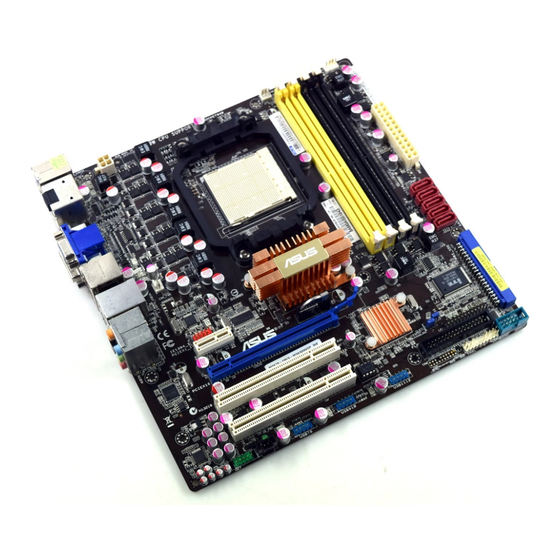
Page 22: Motherboard.overview
Motherboard overview 1.5.1. Motherboard.layout KB_USB56 ATX12V HDMI- SPDIFO ESATA_ USB34 LAN1_USB12 AUDIO IE1394_1 PCIEX1_1 8111C ALC1200 SPDIF_OUT AAFP 1-10 24.4cm (9.6in) AMD 780G 9LPRS485 CR2032 3V Lithium Cell CMOS Power PCIEX16 M3A78-EM PCI1 PCI2 BIOS SB_PWR USB910 USB78 PWR_FAN CPU_FAN SATA6 SATA5 SATA3... -
Page 23: Placement Direction
1.5.3. Screw.holes Place eight (8) screws into the holes indicated by circles to secure the motherboard to the chassis. Do not overtighten the screws! Doing so can damage the motherboard. Place.this.side.towards. the.rear.of.the.chassis ASUS M3A78-EM M3A78-EM 1-11... -
Page 24: Central.processing.unit.(Cpu)
Central Processing Unit (CPU) The motherboard comes with an AM2+ / AM2 socket designed for AMD® Phenom™ FX / Phenom / Athlon™ / Sempron™ processor. The AM2+/AM2 socket has a different pinout from the 940-pin socket designed for the AMD Opteron processor. Ensure you use a CPU designed for the AM2+/AM2 socket. - Page 25 Connect the CPU fan cable to the CPU_FAN connector on the motherboard. M3A78-EM M3A78-EM CPU Fan Connector Do not forget to connect the CPU fan connector! Hardware monitoring errors can occur if you fail to plug this connector. ASUS M3A78-EM Small.triangle Gold.triangle CPU_FAN 1-13...
-
Page 26: Installing The Heatsink And Fan
1.6.2. Installing.the.heatsink.and.fan The AMD Phenom™ FX / Phenom / Athlon™ / Sempron™ processor requires a specially designed heatsink and fan assembly to ensure optimum thermal condition and performance. Ensure that you use only qualified heatsink and fan assembly. Follow these steps to install the CPU heatsink and fan. Place the heatsink on top of the installed CPU, making sure that the heatsink fits properly on the retention module base. - Page 27 Push down the retention bracket lock on the retention mechanism to secure the heatsink and fan to the module base. ASUS M3A78-EM 1-15...
-
Page 28: System.memory
System memory 1.7.1. Overview The motherboard comes with four Double Data Rate 2 (DDR2) Dual Inline Memory Modules (DIMM) sockets. A DDR2 module has the same physical dimensions as a DDR DIMM but has a 240-pin footprint compared to the 184-pin DDR DIMM. DDR2 DIMMs are notched differently to prevent installation on a DDR DIMM socket. - Page 29 The motherboard can support 8 GB physical memory on the operating system listed below. You may install a maximum of 2 GB DIMMs on each slot. Windows Windows ASUS M3A78-EM .Vista./.XP.32-bit.version. ® 64-bit XP Professional x64 Edition ®...
- Page 30 Transcend TX1066QLJ-2GK1GB OCZ2N1066SR2DK GEIL GE22GB1066C5DC GEIL GE24GB1066C5QC Due to AMD CPU limitation, DDR2 1066 is supported by AM2+ CPU for one DIMM per channel only. Refer to www.asus.com for the supported CPU models. DDR2-800.MHz.capability Size Vendor Part.No. Kingston KHX6400D2LL/1G 512MB...
- Page 31 Dual-channel memory configuration C*: Supports four modules inserted into both the yellow slots and the black slots as two pairs of Dual-channel memory configuration Visit the ASUS website for the latest DDR2 DIMM modules for this motherboard. ASUS M3A78-EM Chip.Brand .Chip.No.
-
Page 32: Installing A Dimm
1.7.3. Installing.a.DIMM Make sure to unplug the power supply before adding or removing DIMMs or other system components. Failure to do so may cause severe damage to both the motherboard and the components. Unlock a DIMM socket by pressing the retaining clips outward. Align a DIMM on the socket such that the notch on the DIMM matches the break on the socket. -
Page 33: Expansion.slots
Turn on the system and change the necessary BIOS settings, if any. See Chapter 2 for information on BIOS setup. Assign an IRQ to the card. Refer to the tables on the next page. Install the software drivers for the expansion card. ASUS M3A78-EM 1-21... - Page 34 Interrupt.assignments Standard.function System timer Standard 101/102-Key or Microsoft Natural Keyboard Programmable interrupt controller Standard OpenHCI USB Host Controller Communications Port (COM 1) ACPI IRQ Holder for PCI IRQ Steering (free) (free) System CMOS / Real Time Clock SCI IRQ used by ACPI bus Standard PCI Graphics Adapter (VGA) (free) Microsoft PS/2 Port Mouse...
-
Page 35: Irq Assignments For This Motherboard
When using PCI cards on shared slots, ensure that the drivers support “Share IRQ” or that the cards do not need IRQ assignments; otherwise, conflicts will arise between the two PCI groups, making the system unstable and the card inoperable. ASUS M3A78-EM shared – –... -
Page 36: Pci Slots
1.8.3. PCI.slots The PCI slots support cards such as a LAN card, SCSI card, USB card, and other cards that comply with PCI specifications. The photo shows a LAN card installed on a PCI slot. 1.8.4. PCI.Express.x1.slot This motherboard supports PCI Express x1 network cards, SCSI cards and other cards that comply with the PCI Express specifications. -
Page 37: Clear Rtc Ram
You do not need to clear the RTC when the system hangs due to overclocking. For system failure due to overclocking, use the C.P.R. (CPU Parameter Recall) feature. Shut down and reboot the system so the BIOS can automatically reset parameter settings to default values. ASUS M3A78-EM CLRTC Normal Clear RTC... -
Page 38: 1.10 Connectors
1.10 Connectors 1.10.1. Rear.panel.connectors PS/2.keyboard/Mouse.Combo.port.(purple). This port is for a PS/2 keyboard or mouse. Optical.S/PDIF.Out.port..This port connects an external audio output device via a optical S/PDIF cable. HDMI.port. This port is for a High-Definition Multimedia Interface (HDMI) connector, and is HDCP compliant allowing playback of HD DVD, Blu-Ray and other protected content. - Page 39 – Rear Speaker Out Gray – Ensure the audio device of Sound playback is Realtek High Definition Audio (the.name.may.be.different.based.on.the.OS). Go to Start.>.Control.Panel.>. Sounds.and.Audio.Devices.>.Sound.Playback to configure the setting. ASUS M3A78-EM Status Description 10 Mbps connection ORANGE 100 Mbps connection GREEN 1 Gbps connection...
- Page 40 14.. USB.2.0.ports.1.and.2. These two 4-pin Universal Serial Bus (USB) ports are available for connecting USB 2.0 devices. 15.. External.SATA.port. This port connects to an external Serial ATA hard disk drive. DO NOT insert different connectors to the external SATA port. To use hot-plug, set the OnChip SATA.Type in the BIOS settings to [AHCI].
-
Page 41: Internal Connectors
The serial port bracket (COM1) is purchased separately. M3A78-EM M3A78-EM COM Port Connector ASUS M3A78-EM FLOPPY PIN1 NOTE: Orient the red markings on the floppy ribbon cable to PIN 1. - Page 42 IDE.connector.(40-1.pin.PRI_IDE) The onboard IDE connector is for an Ultra DMA 133/100/66 signal cable. There are three connectors on each Ultra DMA 133/100/66 signal cable: blue, black, and gray. Connect the blue connector to the motherboard’s IDE connector, then select one of the following modes to configure your device(s). Single device Two devices •...
- Page 43 OnChip.SATA.Type item in the BIOS to [RAID]. See page 2-20 for details. • If you want to do the task as GHOST, we suggest you connect the original disk to the SATA5 or SATA6. ASUS M3A78-EM SATA6 SATA5 SATA3 SATA2 SATA1 XP Service Pack 1 before using Serial ATA.
- Page 44 Power,.CPU,.and.Chassis.Fan.connectors. (3-pin.PWR_FAN,.4-pin.CPU_FAN,.3-pin.CHA_FAN) The fan connectors support cooling fans of 350mA~740mA (8.88W max.) or a total of 1A~2.22A (26.64W max.) at +12V. Connect the fan cables to the fan connectors on the motherboard, making sure that the black wire of each cable matches the ground pin of the connector.
- Page 45 The USB 2.0 module is purchased separately. Optical.drive.audio.in.connector.(4-pin.CD) This connector allows you to receive stereo audio input from sound sources such as a CD-ROM, TV tuner, or MPEG card. M3A78-EM M3A78-EM Internal Audio Connector ASUS M3A78-EM USB78 USB910 (black) USB1112 1-33...
- Page 46 Digital.audio.connector.(4-1.pin.SPDIF_OUT) This connector is for an additional Sony/Philips Digital Interface (S/PDIF) port(s). Connect the HDMI module cable to this connector, then install the module to a slot opening at the back of the system chassis. M3A78-EM M3A78-EM Digital Audio Connector Ensure the audio device of Sound playback is Realtek High Definition Audio (the.name.may.be.different.based.on.the.OS).
-
Page 47: Front Panel Audio Connector
[AC97]. See page 2-27 for details. • Make sure the audio device of Sound playback is Realtek High Definition Audio.(the.name.may.be.different.based.on.the.OS). Go to Start.>. Control.Panel.>.Sounds.and.Audio.Devices.>.Sound.Playback to configure the setting. ASUS M3A78-EM Azalia-compliant Legacy AC 97-compliant pin definition pin definition AAFP... -
Page 48: Ieee 1394A Port Connector
11.. Chassis.intrusion.connector.(4-1.pin.CHASSIS) This connector is for a chassis-mounted intrusion detection sensor or switch. Connect one end of the chassis intrusion sensor or switch cable to this connector. The chassis intrusion sensor or switch sends a high-level signal to this connector when a chassis component is removed or replaced. The signal is then generated as a chassis intrusion event. -
Page 49: Atx Power Connectors
You can attach a FireWire/1394 cable to this connector if your chassis suppots the front panel IEEE1394 port. Connect the 1394 cable to ASUS Q-Connector (1394, red) first, and then install the Q-Connector (1394) to the 1394 connector onboard. -
Page 50: System Panel Connector
14.. System.panel.connector.(20-8.pin.PANEL) This connector supports several chassis-mounted functions. M3A78-EM M3A78-EM System Panel Connector • System power LED This 2-pin connector is for the system power LED. Connect the chassis power LED cable to this connector. The system power LED lights up when you turn on the system power, and blinks when the system is in sleep mode. - Page 51 Q-Connector (system panel) You can use ASUS Q-Connector to connect / disconnect chassis front panel cables by only a few steps. Directions below shows how to install ASUS Q-Connector. Step1. Connect correct front panel to ASUS Q-Connector first. You can refer to the marking on Q-Connector itself to know the detail pin definition.
- Page 52 1-40 Chapter 1: Product introduction...
-
Page 53: Bios Setup
This chapter tells how to change the system settings through the BIOS Setup menus. Detailed descriptions of the BIOS parameters are also provided. BIOS setup... -
Page 54: Chapter 2: Bios Setup
ASUS.CrashFree.BIOS.3: Updates the BIOS using a bootable floppy disk, a USB flash disk or the motherboard Support DVD when the BIOS file fails or gets corrupted. ASUS.EZ.Flash.2: Updates the BIOS using a floppy disk or a USB flash disk during POST. ASUS.Update: Updates the BIOS in Windows® environment. -
Page 55: Afudos Utility
Make sure that the floppy disk is not write-protected and has at least 1.2 MB free space to save the file. • The succeeding BIOS screens are for reference only. The actual BIOS screen displays may not be same as shown. ASUS M3A78-EM desktop, then select Computer. ®... - Page 56 Updating the BIOS file To update the BIOS file using the AFUDOS utility: Visit the ASUS website at www.asus.com and download the latest BIOS file for the motherboard. Save the BIOS file to a bootable floppy disk. Write the BIOS filename on a piece of paper. You need to type the exact BIOS filename at the DOS prompt.
- Page 57 The utility verifies the file and starts updating the BIOS. A:\>afudos /iM3A78EM.rom AMI Firmware Update Utility - Version 1.19(ASUS V2.07(03.11.24BB)) Copyright (C) 2002 American Megatrends, Inc. All rights reserved. WARNING!! Do not turn off power during flash BIOS Reading file ... done Reading flash ...
-
Page 58: Asus Crashfree Bios 3 Utility
2.1.3. ASUS.CrashFree.BIOS.3.utility The ASUS CrashFree BIOS 3 is an auto recovery tool that allows you to restore the BIOS file when it fails or gets corrupted during the updating process. You can update a corrupted BIOS file using the motherboard Support DVD , the floppy disk or the USB flash disk that contains the updated BIOS file. - Page 59 Restart the system after the utility completes the updating process. The recovered BIOS may not be the latest BIOS version for this motherboard. Visit the ASUS website at www.asus.com to download the latest BIOS file. Recovering the BIOS from the USB flash disk To recover the BIOS from the USB flash disk: Insert the USB flash disk that contains BIOS file to the USB port.
-
Page 60: Asus Ez Flash 2 Utility
2.1.4. ASUS.EZ.Flash.2.utility The ASUS EZ Flash 2 feature allows you to update the BIOS without having to go through the long process of booting from a floppy disk and using a DOS-based utility. The EZ Flash 2 utility is built-in the BIOS chip so it is accessible by pressing <Alt>.+.<F2>... -
Page 61: Asus Update Utility
DO NOT shut down or reset the system while updating the BIOS to prevent system boot failure! 2.1.5. ASUS.Update.utility The ASUS Update is a utility that allows you to manage, save, and update the motherboard BIOS in Windows • Save the current BIOS file •... - Page 62 Updating.the.BIOS.through.the.Internet To update the BIOS through the Internet: Launch the ASUS Update utility from the Windows >.Programs.>.ASUS.>.ASUSUpdate.>.ASUSUpdate. The ASUS Update main window appears. Select Update BIOS from the Internet option from the drop-down menu, then click Next. 2-10 desktop by clicking Start.
- Page 63 Updating the BIOS through a BIOS file To update the BIOS through a BIOS file: Launch the ASUS Update utility from the Windows >.Programs.>.ASUS.>.ASUSUpdate.>.ASUSUpdate. The ASUS Update main window appears. Select Update BIOS from a file option from the drop-down menu, then click Next.
-
Page 64: Bios.setup.program
The BIOS setup screens shown in this section are for reference purposes only, and may not exactly match what you see on your screen. • Visit the ASUS website at www.asus.com to download the latest BIOS file for this motherboard. 2-12... -
Page 65: Bios Menu Screen
The BIOS setup screens shown in this chapter are for reference purposes only, and may not exactly match what you see on your screen. • Visit the ASUS website (www.asus.com) to download the latest BIOS information. ASUS M3A78-EM Configuration fields... -
Page 66: Navigation Keys
2.2.3. Navigation.keys At the bottom right corner of a menu screen are the navigation keys for that particular menu. Use the navigation keys to select items in the menu and change the settings. Some of the navigation keys differ from one screen to another. 2.2.4. -
Page 67: Pop-Up Window
Primary IDE Master Primary IDE Slave SATA1 SATA2 SATA3 SATA5 SATA6 E-SATA SATA Configuration System Information v02.61 (C)Copyright 1985-2008, American Megatrends, Inc. ASUS M3A78-EM BIOS SETUP UTILITY Boot Tools Exit [Tue 11/19/2007] [1.44M, 3.5 in] Options :[Not Detected] Disabled :[Not Detected] 360K, 5.25 in. -
Page 68: Main.menu
Main menu When you enter the BIOS Setup program, the Main menu screen appears, giving you an overview of the basic system information. Refer to section “2.2.1 BIOS menu screen” for information on the menu screen items and how to navigate through them. Main Advanced Main Settings... -
Page 69: Primary Ide Master/Slave
When set to [Disabled], the data transfer from and to the device occurs one sector at a time. Configuration options: [Disabled] [Auto] ASUS M3A78-EM Select the type of device connected to the system. -
Page 70: Sata 1, 2, 3, 5, 6, And E-Sata
PIO.Mode.[Auto] Selects the PIO mode. Configuration options: [Auto] [0] [1] [2] [3] [4] DMA.Mode.[Auto] Selects the DMA mode. Configuration options: [Auto] SMART.Monitoring.[Auto] Sets the Smart Monitoring, Analysis, and Reporting Technology. Configuration options: [Auto] [Disabled] [Enabled] 32Bit.Data.Transfer.[Disabled] Enables or disables 32-bit data transfer. Configuration options: [Disabled] [Enabled] 2.3.5. -
Page 71: Sata Configuration
Select an item then press <Enter> to display the sub-menu. Main Storage Configuration OnChip SATA Channel OnChip SATA Type SATA IDE Combined Mode OnChip.SATA.Channel.[Enabled] Enables or disables OnChip SATA Channel. Configuration options: [Disabled] [Enabled] ASUS M3A78-EM BIOS SETUP UTILITY [Enabled] [SATA] [Enabled] Options Disabled Enabled 2-19... -
Page 72: System Information
OnChip.SATA.Type.[SATA] This item appears only when you set the OnChip SATA Channel item to [Enabled]. Allows you to set the OnChip SATA Type. Configuration options: [SATA] [RAID] [AHCI] If you want to boot the system from a hard disk drive included in a created RAID set, copy the RAID driver from the Support DVD to a floppy before you install an operating system to the selected hard disk drive. -
Page 73: Advanced.menu
DRAM Timing Mode Memory OverVoltage v02.61 (C)Copyright 1985-2008, American Megatrends, Inc. Scroll down to display the following items: Chipset Voltage Chipset OverVoltage v02.61 (C)Copyright 1985-2008, American Megatrends, Inc. ASUS M3A78-EM BIOS SETUP UTILITY Boot Tools Exit BIOS SETUP UTILITY Boot Tools... - Page 74 CPU.Overclocking.[Auto] Allows selection of CPU overclocking options to achieve desired CPU internal frequency. Select either one of the preset overclocking. Configuration options: [Auto] [Manual] [Overclock Profile] [Test Mode] GPU.Overclocking.[Auto] Allows you to configure overclocking of GPU. Configuration options: [Auto] [Manual] PCIE.Overclocking.[Auto] Allows you to to configure overclocking of PCIE.
-
Page 75: Cpu Configuration
Enables or disables Secure Virtual Machine Mode (SVM) Configuration options: [Disabled] [Enabled] Cool ‘n’ Quiet [Enabled] Enables or disables the AMD Cool ‘n’ Quiet technology. Configuration options: [Enabled] [Disabled] ASUS M3A78-EM BIOS SETUP UTILITY NB Clk: N/A [Disabled] [Enabled] [Enabled]... -
Page 76: Chipset
2.4.3. Chipset Chipset Configuration NorthBridge Configuration Internal Graphics NorthBridge Configuration NorthBridge Chipset Configuration Memory Configuration ECC Configuration Memory CLK CAS Latency(Tc1) RAS/CAS Delay(Trcd) Row Precharge Time(Trp) Min Active RAS(Tras) RAS/RAS Delay(Trrd) Row Cycle(Trc) Memory Configuration Advanced Memory Configuration Bank Interleaving Channel Interleaving MemClk Tristate C3/ATLVID Memory Hole Remapping... -
Page 77: Ecc Configuration
DRAM BG Scrub Data Cache BG Scrub L2 Cache BG Scrub L3 Cache BG Scrub ECC Mode [Disabled] Allows you to set the ECC mode. Configuration options: [Disabled] [Basic] [Good] [Super] [Max] [User] ASUS M3A78-EM [Disabled] [Disabled] [Disabled] [Disabled] [Disabled] [Disabled]... - Page 78 Internal.Graphics Internal Graphics Primary Video Controller UMA Frame Buffer Size Surround View AMD 780 HD Audio DisplayPort Config Primary.Video.Controller.[GFX0-GPP-IGFX-PCI] Configuration options: [GFX0-GPP-IGFX-PCI] [GPP-GFX0-IGFX-PCI] [PCI-GFX0-GPP-IGFX] [IGFX-GFX0-GPP-PCI] GFX0: VGA out port on a graphics card connected into a PCIE x16 slot GPP: VGA out port on a graphics card connected into a PCIE x1 slot IGFX Internal VGA out port...
-
Page 79: Onboard Device Configuration
Enables or disables the high definition audio controller. Configuration options: [Enabled] [Disabled] Front.Panel.Select.[HD.Audio] Configuration options: [HD Audio] [AC97] SPDIF_OUT Mode Setting [SPDIF Output] Allows you to set the SPDIF_OUT mode. Configuration options: [HDMI Output] [SPDIF Output] ASUS M3A78-EM BIOS SETUP UTILITY [3F8/IRQ4] [378] [Normal] [IRQ7] [Enabled]... -
Page 80: Pcipnp
OnBoard.LAN.Controller.[Enabled] Configuration options: [Enabled] [Disabled] OnBoard LAN Boot ROM [Disabled] Configuration options: [Disabled] [Enabled] 1394.Controller.[Enabled] Allows you to enable or disable the 1394 controller. Configuration options: [Disabled] [Enabled] 2.4.5. PCIPnP The PCI.PnP menu items allow you to change the advanced settings for PCI/PnP devices. -
Page 81: Usb Configuration
If no USB device is detected, the legacy USB support is disabled. Configuration options: [Disabled] [Enabled] [Auto] USB.2.0.Controller.Mode.[HiSpeed] Allows you to configure the USB 2.0 controller in HiSpeed (480 Mbps) or Full Speed (12 Mbps). Configuration options: [FullSpeed] [HiSpeed] ASUS M3A78-EM BIOS SETUP UTILITY [Enabled] [Enabled] [Auto]... -
Page 82: Power.menu
Power menu The Power menu items allow you to change the settings for the Advanced Configuration and Power Interface (ACPI) and the Advanced Power Management (APM). Select an item then press <Enter> to display the configuration options. Main Advanced Power Settings Suspend Mode ACPI Support ACPI APIC support... -
Page 83: Apm Configuration
Power.on.From.S5.By.PS/2.KB/MS.[Disabled] Enables or disables PS/2 Keyboard/Mouse to generate a wake event. Configuration options: [Disabled] [Enabled] Power.on.From.S5.By.RTC.Alarm.[Disabled] Enables or disables RTC to generate a wake event. Configuration options: [Disabled] [Enabled] ASUS M3A78-EM BIOS SETUP UTILITY [Always Off] [Disabled] [Disabled] [Disabled] Options... -
Page 84: Hw Monitor Configuration
2.5.5 HW Monitor Configuration Power Hardware Monitor CPU Temperature MB Temperature CPU Fan Speed Chassis Fan Speed Power Fan Speed VCORE Voltage 3.3V Voltage 5V Voltage 12V Voltage Smart Q-FAN Function Fan Auto Mode Start Voltage Fan Auto Mode Start Speed Temp Fan Auto Mode Full Speed Temp v02.58 (C)Copyright 1985-2006, American Megatrends, Inc. -
Page 85: Boot.menu
Smart Q-Fan Function [Enabled] Allows you to enable or disable the ASUS Q-Fan feature that smartly adjusts the fan speeds for more efficient system operation. Configuration options: [Disabled] [Enabled] Fan.Auto.Mode.Start.Voltage.[5.0V] Allows you to select the fan auto mode start voltage. Configuration options: [4.0V] [4.5V] [5.0V] [5.5V] [6.0V]... -
Page 86: Boot Device Priority
2.6.1. Boot.Device.Priority Boot Boot Device Priority 1st Boot Device 2nd Boot Device 3rd Boot Device v02.61 (C)Copyright 1985-2008, American Megatrends, Inc. 1st.~.xxth.Boot.Device.[xxx.Drive] These items specify the boot device priority sequence from the available devices. The number of device items that appears on the screen depends on the number of devices installed in the system. - Page 87 Full.Screen.Logo.[Enabled] This allows you to enable or disable the full screen logo display feature. Configuration options: [Disabled] [Enabled] Set this item to [Enabled] to use the ASUS MyLogo2™ feature. AddOn.ROM.Display.Mode.[Force.BIOS] Sets the display mode for option ROM. Configuration options: [Force BIOS] [Keep Current] Bootup.Num-Lock.[On]...
-
Page 88: Security
2.6.3. Security The Security menu items allow you to change the system security settings. Select an item then press <Enter> to display the configuration options. Security Settings Supervisor Password User Password Change Supervisor Password Change User Passward Change.Supervisor.Password Select this item to set or change the supervisor password. The Supervisor. Password item on top of the screen shows the default Not.Installed. - Page 89 When set to [Setup], BIOS checks for user password when accessing the Setup utility. When set to [Always], BIOS checks for user password both when accessing Setup and booting the system. Configuration options: [Setup] [Always] ASUS M3A78-EM [Full Access] [Setup] <Enter>...
-
Page 90: Tools.menu
2.7.1. ASUS.EZ.Flash.2 Allows you to run ASUS EZ Flash 2. When you press <Enter>, a confirmation message appears. Use the left/right arrow key to select between [Yes] or [No], then press <Enter> to confirm your choice. Please see section 2.1.4 for details. -
Page 91: Ai Net 2
2.7.2. Express.Gate.[Enabled] Allows you to enable or disable the ASUS Express Gate feature. The ASUS Express Gate feature is a unique instant-on environment that provides quick access to the Internet browser and Skype. Configuration options: [Enabled] [Disabled] Enter OS Timer [10 Seconds] Sets countdown duration that the system waits at the Express Gate’s first... -
Page 92: Exit.menu
Exit menu The Exit menu items allow you to load the optimal or failsafe default values for the BIOS items, and save or discard your changes to the BIOS items. Main Advanced Exit Options Exit & Save Changes Exit & Discard Changes Discard Changes Load Setup Defaults Pressing <Esc>... -
Page 93: Software Support
This chapter describes the contents of the Support DVD that comes with the motherboard package. Software support... -
Page 94: Chapter 3: Software Support
The contents of the Support DVD are subject to change at any time without notice. Visit the ASUS website at www.asus.com for updates. 3.2.1. Running.the.Support.DVD Place the Support DVD to the optical drive. The DVD automatically displays the Drivers menu if Autorun is enabled in your computer. -
Page 95: Drivers Menu
Drivers.menu The Drivers menu shows the available device drivers if the system detects installed devices. Install the necessary drivers to activate the devices. ASUS.InstAll.-.Installation.Wizard.for.Drivers Launches the ASUS InstallAll - drivers installation wizard. AMD.Chipset.Driver Installs the AMD chipset driver. Realtek.Audio.Driver Installs the Realtek audio driver. -
Page 96: Utilities Menu
This utility helps you keep your computer in healthy operating condition. ASUS.Update. The ASUS Update utility allows you to update the motherboard BIOS in a Windows environment. This utility requires an Internet connection either through a ®... - Page 97 Portable Document Format (PDF). to show the rest of the utilities under the Utilities menu. Click WinZip.11 Installs the Winzip utility for easy file-compression and protection. Ulead.Burn.Now Installs the Ulead Burn.Now application for Audio DVD, CD and data disc creation. ASUS M3A78-EM...
-
Page 98: Make Disk Menu
Ulead.PhotoImpact.12.SE Installs the PhotoImpact image editing software. ASUS.Express.Gate.Installer Installs the ASUS Expres Gate. Anti-Virus.Utility Installs the anti-virus application that detects and protects your computer from viruses that destroy data. Anti-Virus.Utility.Download Downloads and installs the latest anti-virus application. ASUS.AI.Nap Installs the ASUS AI Nap. -
Page 99: Manual Menu
Most user manual files are in Portable Document Format (PDF). Install the Adobe Acrobat ® ® file. ASUS M3A78-EM Serial ATA (SATA) RAID/AHCI Vista32 driver disk. ® Serial ATA (SATA) RAID/AHCI Vista64 driver disk. ® Serial ATA (SATA) RAID/AHCI driver for XP/XP 64bit. -
Page 100: Asus Contact Information
3.2.6. ASUS.Contact.information Click the Contact tab to display the ASUS contact information. You can also find this information on the inside front cover of this user guide. 3.2.7. Other.information The icons on the top right corner of the screen give additional information on the motherboard and the contents of the Support DVD. - Page 101 Browse.this.DVD Displays the Support DVD contents in graphical format. Technical.support.Form Displays the ASUS Technical Support Request Form that you have to fill out when requesting technical support. Filelist Displays the contents of the Support DVD and a brief description of each in text format.
- Page 102 3-10 Chapter 3: Software support...
-
Page 103: Appendix
This chapter describes how to enable ATI Hybrid CrossFireX under Windows Vista Appendix... -
Page 104: Ati ® Hybrid Crossfirex
Hybrid CrossFireX™ ® The motherboard supports the ATI to install multi-graphics processing units (GPU) CrossFireX cards. A.1. System.requirements Before using ATI Hybrid CrossFireX, ensure that your system meets the following basic requirements: Operating.System:.Windows Memory.capacity:. Minimum 1GB CPU:. AM2+ On-board.graphics.card.RAM: 256MB Add-on.GPU:.HD2400 PRO/HD2400 XT/HD3450/HD3470 We recommend that you use a graphics card with an HD2400 PRO GPU. -
Page 105: Installing Amd Chipset Driver
Enable.CrossFire™ check box. When a confirmation message pops up, click Yes. The screen blacks out for about one minute. Click OK. The add-on graphics card is set to be the main monitor. ASUS M3A78-EM .Control.Center ® desktop, then click ATI.CATALYST(R).Control. ®... - Page 106 Using.the.onboard.graphics.card Right-click on the Windows Center from the shortcut menu. The ATI CATALYST Control Center screen appears. Click.Graphics.Settings > CrossFire™, then clear the Enable.CrossFire™ check box. When a confirmation message pops up, click Yes. The screen blacks out for about one minute. Click OK.
- Page 107 Adapter. Select ATI.Radeon. HD.3200.Graphics.[Gabbs,.G. HW173]. Click OK, and then Yes from the confirmation window. Follow steps 6 to step 8 on Using. the.onboard.graphics.card to complete the process of setting up the onboard graphics card as your main monitor. ASUS M3A78-EM...
- Page 108 Appendix...