Asus M3A GREEN User Manual
User manual
Hide thumbs
Also See for M3A GREEN:
- User manual (8 pages) ,
- User manual (44 pages) ,
- User manual (134 pages)
Table of Contents
Advertisement
Quick Links
Advertisement
Table of Contents

Related Manuals for Asus M3A GREEN


Summary of Contents for Asus M3A GREEN
- Page 1 M3A-H/ HDMI...
- Page 2 Product warranty or service will not be extended if: (1) the product is repaired, modified or altered, unless such repair, modification of alteration is authorized in writing by ASUS; or (2) the serial number of the product is defaced or missing.
-
Page 3: Table Of Contents
Welcome! ..................1-2 Package contents ................. 1-2 Special features ................1-3 1.3.1 Product highlights ............1-3 1.3.2 ASUS AI Lifestyle unique features ........1-5 1.3.3 ASUS intelligent performance and overclocking features ............1-7 Before you proceed ..............1-8 Motherboard overview ..............1-9 1.5.1... -
Page 4: Contents
BIOS setup Managing and updating your BIOS ..........2-2 2.1.1 Creating a bootable floppy disk ........2-3 2.1.2 ASUS EZ Flash 2 utility ........... 2-4 2.1.3 AFUDOS utility ..............2-5 2.1.4 ASUS Update utility ............2-7 BIOS setup program ..............2-10 2.2.1... - Page 5 Boot Device Priority ............2-35 2.6.2 Boot Settings Configuration .......... 2-36 2.6.3 Security ................. 2-37 Tools menu ................. 2-39 2.7.1 ASUS EZ Flash 2 ............2-39 2.7.2 Express Gate Lite ............2-40 2.7.3 ASUS O.C. Profile ............2-41 Exit menu ..................2-42 Chapter 3 Software support Installing an operating system ...........
-
Page 6: Notices
Notices Federal Communications Commission Statement This device complies with Part 15 of the FCC Rules. Operation is subject to the following two conditions: • This device may not cause harmful interference, and • This device must accept any interference received including interference that may cause undesired operation. -
Page 7: Safety Information
Safety information Electrical safety • To prevent electrical shock hazard, disconnect the power cable from the electrical outlet before relocating the system. • When adding or removing devices to or from the system, ensure that the power cables for the devices are unplugged before the signal cables are connected. If possible, disconnect all power cables from the existing system before you add a device. -
Page 8: About This Guide
Refer to the following sources for additional information and for product and software updates. ASUS websites The ASUS website provides updated information on ASUS hardware and software products. Refer to the ASUS contact information. Optional documentation Your product package may include optional documentation, such as warranty flyers, that may have been added by your dealer. -
Page 9: Conventions Used In This Guide
Conventions used in this guide To make sure that you perform certain tasks properly, take note of the following symbols used throughout this manual. DANGER/WARNING: Information to prevent injury to yourself when trying to complete a task. CAUTION: Information to prevent damage to the components when trying to complete a task. -
Page 10: M3A-H/Hdmi Specifications Summary
- Supports up to 8 GB system memory �DDR2 1066 is supported by some of the AM2+ CPUs only. Refer to www.asus.com for the supported CPU Refer to www.asus.com for the supported CPU models and the Memory QVL (Qualified Vendors Lists). - Page 11 M3A-H/HDMI specifications summary ASUS AI Lifestyle ASUS Quiet Thermal Solution: unique features - ASUS 4+1 Phase Power Design - ASUS AI Gear 2 - ASUS AI Nap - ASUS Q-Fan 2 ASUS Crystal Sound - ASUS Noise Filter ASUS EZ DIY...
- Page 12 1 x 4-pin ATX 12V Power connector 1 x System Panel (Q-Connector) BIOS features 8 Mb Flash ROM, AMI BIOS, PnP, DMI 2.0, WfM2.0, SM BIOS 2.3, ACPI 2.0a, ASUS EZ Flash 2 Support DVD contents Drivers Express Gate Lite...
-
Page 13: Chapter 1: Product Introduction
This chapter describes the motherboard features and the new technologies it supports. Chapter 1: Product introduction... -
Page 14: Welcome
® The motherboard delivers a host of new features and latest technologies, making it another standout in the long line of ASUS quality motherboards! Before you start installing the motherboard, and hardware devices on it, check the items in your package with the list below. -
Page 15: Special Features
Green ASUS This motherboard and its packaging comply with the European Union’s Restriction on the use of Hazardous Substances (RoHS). This is in line with the ASUS vision of creating environment-friendly and recyclable products/packaging to safeguard consumers’ health while minimizing the impact on the environment. - Page 16 3D graphics and other memory demanding applications. See page 1-15 for details. DDR2 1066 is supported by some of the AM2+ CPUs only. Refer to www.asus. com for the supported CPU models. Hybrid CrossFire Technology ®...
-
Page 17: Asus Ai Lifestyle Unique Features
1.3.2 ASUS AI Lifestyle unique features ASUS Quiet Thermal Solution ASUS Quiet Thermal solution makes system more stable and enhances the overclocking capability. AI Gear 2 AI Gear 2 allows you to choose from profiles to adjust CPU frequency and vCore voltage, minimizing system noise and saving CPU power consumption at most. -
Page 18: Asus Ez Diy
BIOS or back up your favorite settings. ASUS Express Gate Lite Just 5 seconds to boot up, the ASUS Express Gate Lite allows you to instantly surf the Internet without entering Windows. You can now enjoy Skype, IM, YouTube, webmail and Internet file downloads and sharing whenever and wherever you want! See pages 2-40 and 3-10 for details . -
Page 19: Asus Intelligent Performance And Overclocking Features
Smart Support DVD This feature provides a checklist that allows the user to know which drivers are already installed, as well as those that are not. When using ASUS PC Probe II, you can easily monitor the critical components of the computer. -
Page 20: Before You Proceed
Before you proceed Take note of the following precautions before you install motherboard components or change any motherboard settings. • Unplug the power cord from the wall socket before touching any component. • Use a grounded wrist strap or touch a safely grounded object or a metal object, such as the power supply case, before handling components to avoid damaging them due to static electricity •... -
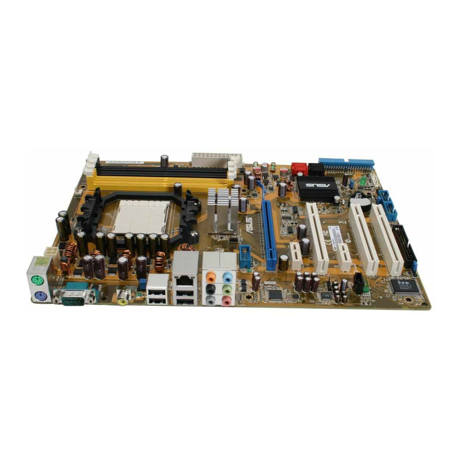
Page 21: Motherboard Overview
SB_PWR PCI1 SATA1 SATA4 PCI2 CLRTC SATA2 SATA5 USBPW9-12 SATA3 SATA6 ALC1200 USBPW5-8 PCI3 BIOS CHASSIS SPDIF_OUT PANEL FLOPPY USB1112 USB910 USB78 USB56 AAFP Refer to 1.10 Connectors for more information about rear panel connectors and internal connectors. ASUS M3A-H/HDMI... -
Page 22: Placement Direction
1.5.2 Placement direction When installing the motherboard, make sure that you place it into the chassis in the correct orientation. The edge with external ports goes to the rear part of the chassis as indicated in the image below. 1.5.3 Screw holes Place six (6) screws into the holes indicated by circles to secure the motherboard to the chassis. -
Page 23: Central Processing Unit (Cpu)
Unlock the socket by pressing the lever sideways, then lift it up to a 90°-100° angle. Socket lever Make sure that the socket lever is lifted up to 90°-100° angle, otherwise the CPU does not fit in completely. ASUS M3A-H/HDMI 1-11... - Page 24 Position the CPU above the socket such that the CPU corner with the gold triangle matches the socket corner with a small triangle. Carefully insert the CPU into the socket until it fits in place. Small triangle Gold triangle The CPU fits only in one correct orientation. DO NOT force the CPU into the socket to prevent bending the pins and damaging the CPU! When the CPU is in place, push down the socket lever to secure the...
-
Page 25: Installing The Heatsink And Fan
Retention bracket lock Your boxed CPU heatsink and fan assembly should come with installation instructions for the CPU, heatsink, and the retention mechanism. If the instructions in this section do not match the CPU documentation, follow the latter. ASUS M3A-H/HDMI 1-13... - Page 26 Attach one end of the retention bracket to the retention module base. Align the other end of the retention bracket (near the retention bracket lock) to the retention module base. A clicking sound denotes that the retention bracket is in place. Make sure that the fan and heatsink assembly perfectly fits the retention mechanism module...
-
Page 27: System Memory
You may install 512 MB, 1 GB, and 2 GB unbuffered ECC/non-ECC DDR2 DIMMs into the DIMM sockets. Recommended memory configurations Sockets Mode DIMM_A1 DIMM_A2 DIMM_B1 DIMM_B2 Populated — — — Single-Channel — — Populated — Dual-channel (1) Populated — Populated — Dual-channel (2) Populated Populated Populated Populated ASUS M3A-H/HDMI 1-15... - Page 28 Always use identical DDR2 DIMM pairs for dual channel mode. For optimum compatibility, it is recommended that you obtain memory modules from the same vendor. Visit the ASUS website (www.asus.com) for the latest Qualified Vendors list. Important notice on installing Windows XP 32-bit version ®...
- Page 29 • • NANYA NT5TU64M8BE-25C NANYA NT1GT64U8HB0BY-25C • • NANYA NT5TU64M8CE-25D NANYA NT1GT64U8HCOBY-25D • • NANYA NT5TU128M8CE-AC NANYA NT2GT64U8HC0BY-AC • • 512MB A3R12E3HEF641B9A05 AL6E8E63B8E1K • • • A3R12E3HEF641B9A05 AL7E8E63B-8E1K • • 256MB TwinMOS E2508AB-GE-E ELPIDA 8G-24IK2-EBT • • ASUS M3A-H/HDMI 1-17...
- Page 30 M3A-H/HDMI Motherboard Qualified Vendors Lists (QVL) DDR2-667 MHz capability DIMM socket support (Optional) Chip Size Vendor Chip No. Part No. Brand 256MB KINGSTON HYB18T256800AF3S KVR667D2N5/256 • 256MB KINGSTON 6SBI2D9DCG MICRON KVR667D2N5/256 • KINGSTON E5108AGBG-6E-E KINGSTON KVR667D2N5/1G • • KINGSTON E1108AB-6E-E ELPIDA KVR667D2N5/2G •...
-
Page 31: Memory Configuration
Dual-channel memory configuration. • C*: Supports four modules inserted into both the yellow slots and the black slots as two pairs of Dual-channel memory configuration. Visit the ASUS website for the latest DDR2 QVL. ASUS M3A-H/HDMI 1-19... -
Page 32: Installing A Dimm
1.7.3 Installing a DIMM Make sure to unplug the power supply before adding or removing DIMMs or other system components. Failure to do so may cause severe damage to both the motherboard and the components. Unlock a DIMM socket by pressing DDR2 DIMM notch the retaining clips outward. -
Page 33: Expansion Slots
Turn on the system and change the necessary BIOS settings, if any. See Chapter 2 for information on BIOS setup. Assign an IRQ to the card. Refer to the tables on the next page. Install the software drivers for the expansion card. ASUS M3A-H/HDMI 1-21... -
Page 34: Interrupt Assignments
Interrupt assignments Priority Standard function System timer Keyboard controller – Re-direct to IRQ#9 IRQ holder for PCI steering� Communications port (COM1)� IRQ holder for PCI steering� Floppy disk controller IRQ holder for PCI steering� System CMOS/Real Time Clock IRQ holder for PCI steering� IRQ holder for PCI steering�... -
Page 35: Pci Slots
Vista operation system supports Hybird CrossFire ® mode. • Currently, only AMD HD3470, HD3450, HD2400XT and HD2400Pro ® graphics cards support the Hybrid Crossfire™ function. ™ function. function. • Visit www.amd.com for more information about Hybrid Crossfire™ support. ASUS M3A-H/HDMI 1-23... -
Page 36: Jumpers
Jumpers Clear RTC RAM (CLRTC) This jumper allows you to clear the Real Time Clock (RTC) RAM in CMOS. You can clear the CMOS memory of date, time, and system setup parameters by erasing the CMOS RTC RAM data. The onboard button cell battery powers the RAM data in CMOS, which include system setup information such as system passwords. -
Page 37: Usb Device Wake-Up
(the default is the Space Bar). This feature requires an ATX power supply that can supply at least 500 mA on the +5VSB lead, and a corresponding setting in the BIOS. KBPWR +5VSB (Default) M3A-H/HDMI ® M3A-H/HDMI Keyboard power setting ASUS M3A-H/HDMI 1-25... -
Page 38: 1.10 Connectors
1.10 Connectors 1.10.1 Rear panel connectors PS/2 mouse port (green). This port is for a PS/2 mouse. Video Graphics Adapter (VGA) port. This 15-pin port is for a VGA monitor or other VGA-compatible devices. LAN (RJ-45) port. This port allows Gigabit connection to a Local Area Network (LAN) through a network hub. - Page 39 S/PDIF cable. 13. USB 2.0 ports 3 and 4. These two 4-pin Universal Serial Bus (USB) ports are available for connecting USB 2.0 devices. 14. PS/2 keyboard port (purple). This port is for a PS/2 keyboard. ASUS M3A-H/HDMI 1-27...
-
Page 40: Internal Connectors
1.10.2 Internal connectors Floppy disk drive connector (34-1 pin FLOPPY) This connector is for the provided floppy disk drive (FDD) signal cable. Insert one end of the cable to this connector, then connect the other end to the signal connector at the back of the floppy disk drive. Pin 5 on the connector is removed to prevent incorrect cable connection when using an FDD cable with a covered Pin 5. - Page 41 Ultra DMA cable connector. This prevents incorrect insertion when you connect the IDE cable. • Use the 80-conductor IDE cable for Ultra DMA 133/100/66 IDE devices. If any device jumper is set as “Cable-Select,” make sure all other device jumpers have the same setting. ASUS M3A-H/HDMI 1-29...
- Page 42 Serial ATA connectors (7-pin SATA1-6) These connectors are for the Serial ATA signal cables for Serial ATA 3Gb/s hard disk and optical disk drives. The Serial ATA 3Gb/s is backward compatible with Serial ATA 1.5Gb/s specification. The data transfer rate of the Serial ATA 3Gb/s is faster than the standard parallel ATA with 133 MB/s (Ultra DMA133).
- Page 43 PWR_FAN +12V M3A-H/HDMI FAN connectors Rotation Only the CPU_FAN and CHA_FAN1 connectors support the ASUS Q FAN 2 feature. Digital audio connector (4-1 pin SPDIF_OUT) This connector is for an additional Sony/Philips Digital Interface (S/PDIF) port(s). Connect the S/PDIF module cable to this connector, then install the module to a slot opening at the back of the system chassis.
- Page 44 PIN 1 M3A-H/HDMI USB 2.0 connectors You can connect the front panel USB cable to the ASUS Q-Connector (USB, blue) first, and then install the Q-Connector (USB) to the USB connector onboard if your chassis supports front panel USB ports.
-
Page 45: Serial Port Connectors
Front Panel Support Type item in the BIOS is set to [HD Audio]; if you want to connect an AC`97 front panel audio module to this connector, set the item to [AC97]. See page 2-28 for details. ASUS M3A-H/HDMI 1-33... - Page 46 • If you are uncertain about the minimum power supply requirement for your system, refer to the Recommended Power Supply Wattage Calculator at http://support.asus.com/PowerSupplyCalculator/PSCalculator. aspx?SLanguage=en-us for details. 1-34 Chapter 1: Product introduction...
-
Page 47: System Panel Connector
BIOS settings. Pressing the power switch for more than four seconds while the system is ON turns the system OFF. • Reset button This 2-pin connector is for the chassis-mounted reset button for system reboot without turning off the system power. ASUS M3A-H/HDMI 1-35... - Page 48 13. ASUS Q-Connector (system panel) You can use the ASUS Q-Connector to connect/disconnect chassis front panel cables in a few steps. Refer to the instructions below to install the ASUS Q-Connector. Connect the front panel cables to the ASUS Q-Connector.
-
Page 49: Chapter 2 Bios Setup
This chapter tells how to change the system settings through the BIOS Setup menus. Detailed descriptions of the BIOS parameters are also provided. Chapter 2 BIOS setup... -
Page 50: Managing And Updating Your Bios
The following utilities allow you to manage and update the motherboard Basic Input/Output System (BIOS) setup. ASUS EZ Flash 2 (Updates the BIOS using a floppy disk, USB Flash, or the motherboard support DVD during POST.) ASUS AFUDOS (Updates the BIOS in DOS mode using a bootable floppy disk.) -
Page 51: Creating A Bootable Floppy Disk
Right-click Floppy Disk Drive then click Format to display the Format 3 1/2 Floppy dialog box . d. Select the Create an MS-DOS startup disk check box. e. Click Start. Copy the original or the latest motherboard BIOS file to the bootable floppy disk. ASUS M3A-H/HDMI... -
Page 52: Asus Ez Flash 2 Utility
2.1.2 ASUS EZ Flash 2 utility The ASUS EZ Flash 2 feature allows you to update the BIOS without having to go through the long process of booting from a floppy disk and using a DOS-based utility. The EZ Flash 2 utility is built-in the BIOS chip so it is accessible by pressing <Alt>... -
Page 53: Afudos Utility
Extension name Press <Enter>. The utility copies the current BIOS file to the floppy disk. A:\>afudos /oOLDBIOS1.rom AMI Firmware Update Utility - Version 1.19(ASUS V2.07(03.11.24BB)) Copyright (C) 2002 American Megatrends, Inc. All rights reserved. Reading flash ..done Write to file..ok A:\>... -
Page 54: Updating The Bios File
Updating the BIOS file To update the BIOS file using the AFUDOS utility: Visit the ASUS website (www.asus.com) and download the latest BIOS file for the motherboard. Save the BIOS file to a bootable floppy disk. Write the BIOS filename on a piece of paper. You need to type the exact BIOS filename at the DOS prompt. -
Page 55: Asus Update Utility
2.1.4 ASUS Update utility The ASUS Update is a utility that allows you to manage, save, and update the motherboard BIOS in Windows environment. The ASUS Update utility allows you ® • Save the current BIOS file • Download the latest BIOS file from the Internet •... - Page 56 To update the BIOS through the Internet: Launch the ASUS Update utility from the Windows desktop by clicking Start ® > Programs > ASUS > ASUSUpdate > ASUSUpdate. The ASUS Update main window appears. Select Update BIOS from Select the ASUS FTP site nearest...
- Page 57 To update the BIOS through a BIOS file: Launch the ASUS Update utility from the Windows desktop by clicking Start ® > Programs > ASUS > ASUSUpdate > ASUSUpdate. The ASUS Update main window appears. Select Update BIOS from a file option from the drop-down menu, then click Next.
-
Page 58: Bios Setup Program
The BIOS setup screens shown in this section are for reference purposes only, and may not exactly match what you see on your screen. • Visit the ASUS website (www.asus.com) to download the latest BIOS file for this motherboard. 2-10... -
Page 59: Bios Menu Screen
• The BIOS setup screens shown in this chapter are for reference purposes only, and may not exactly match what you see on your screen. • Visit the ASUS website (www.asus.com) to download the latest BIOS information. 2.2.3 Navigation keys At the bottom right corner of a menu screen are the navigation keys for that particular menu. -
Page 60: Menu Items
Some of the navigation keys differ from one screen to another. 2.2.4 Menu items Use [ENTER], [TAB], System Time [06:22:54] or [SHIFT-TAB] to System Date [Fri 01/18/2008] The highlighted item on the menu select a field. Legacy Diskette A [1.44M, 3.5 in] Use [+] or [-] to Primary IDE Master [WDC WD800JD-00LSA0]... -
Page 61: Main Menu
Allows you to set the system time. 2.3.2 System Date [Day xx/xx/xxxx] Allows you to set the system date. 2.3.3 Legacy Diskette A [1.44M, 3.5 in.] Sets the type of floppy drive installed. Configuration options: [Disabled] [720K , 3.5 in.] [1.44M, 3.5 in.] ASUS M3A-H/HDMI 2-13... -
Page 62: Primary Ide Master/Slave
2.3.4 Primary IDE Master/Slave While entering Setup, the BIOS automatically detects the presence of IDE devices. There is a separate sub-menu for each IDE device. Select a device item then press <Enter> to display the IDE device information. BIOS SETUP UTILITY Main Primary IDE Master Select the type... -
Page 63: Sata1/2/3/4/5/6
LBA/Large Mode [Auto] Enables or disables the LBA mode. Setting to [Auto] enables the LBA mode if the device supports this mode, and if the device was not previously formatted with LBA mode disabled. Configuration options: [Disabled] [Auto] ASUS M3A-H/HDMI 2-15... -
Page 64: Storage Configuration
Block (Multi-sector Transfer) M [Auto] Enables or disables data multi-sectors transfers. When set to [Auto], the data transfer from and to the device occurs multiple sectors at a time if the device supports multi-sector transfer feature. When set to [Disabled], the data transfer from and to the device occurs one sector at a time. -
Page 65: System Information
Installed Size: 1024MB Save and Exit Usable Size : 1024MB Exit v02.61 (C)Copyright 1985-2008, American Megatrends, Inc. AMI BIOS Displays the auto-detected BIOS information. Processor Displays the auto-detected CPU specification. System Memory Displays the auto-detected system memory. ASUS M3A-H/HDMI 2-17... -
Page 66: Advanced Menu
Advanced menu The Advanced menu items allow you to change the settings for the CPU and other system devices. Take caution when changing the settings of the Advanced menu items. Incorrect field values can cause the system to malfunction. The configuration options for this chapter vary depending on the CPU and DIMM model you install on the motherboard. - Page 67 Allows selection of the Processor Voltage. The values range from 0.8000V to 1.7000V with a 0.0125V interval. CPU-NB HT Link Speed [Auto] Allows you to set the CPU-Northbridge HyperTransport link speed. Configuration options: [200 MHz] [400 MHz] [600 MHz] [800 MHz] [1 GHz] [Auto] ASUS M3A-H/HDMI 2-19...
- Page 68 The following three items appears only when you set the Ai Overclocking item to [Manual], [Standard], or [Overclock Profile] and are adjusted by typing the desired values using the numeric keypad and press the <Enter> key. You can also use the <+> and <-> keys to adjust the value. To restore the default setting, type [auto] using the keyboard and press the <Enter>...
-
Page 69: Dram Timing Configuration
The configuration options for some of the following items vary depending on the depending on the DIMMs you install on the motherboard. Memory Clock Mode [Auto] Allows selection of the DRAM Frequency programming method. Configuration options: [Auto] [Limit] [Manual] ASUS M3A-H/HDMI 2-21... - Page 70 Memclock Value [400 MHz] This sub-item appears only when you set the Memory Clock Mode item to [Limit] and [Manual]. Configuration options: [400 MHz] [533 MHz] [667 MHz] [800 MHz] [1066 MHz]� 2T Mode [Auto] Allows selection of the 2T Mode. Configuration options: [Auto] [Disabled] [Enabled] DRAM Timing Mode [Auto] Allows selection of the DRAM Timing Mode.
-
Page 71: Ai Net 2
Allows you to enable or disable LAN cable check during POST. When enabled, the menu reports the cable faults or shorts, and displays the point (length) where the faults or shorts are detected. Configuration options: [Disabled] [Enabled] ASUS M3A-H/HDMI 2-23... -
Page 72: Cpu Configuration
2.4.3 CPU Configuration BIOS SETUP UTILITY Advanced CPU Configuration Enable/Disable Module Version: 13.23 Secure Virtual Machine AGESA Version:3.1.5.0 Mode (SVM) Physical Count: 1 Logical Count: AMD Athlon(tm) 64 Processor 3200+ Revision: F2 Cache L1: 128KB Cache L2: 512KB Cache L3: N/A Speed : 2000MHz, NB Clk: N/A... -
Page 73: Pci Express Configuration
Configuration options: [Disabled] [L0s] [L1] [L0s & L1] NB-SB Port Features NB-SB link ASPM [Disabled] Configuration options: [Disabled] [L1] NP NB-SB VC1 Traffic Support [Disabled] Configuration options: [Enabled] [Disabled] Link Width [Auto] Configuration options: [Auto] [x1] [x2] [x4] ASUS M3A-H/HDMI 2-25... -
Page 74: Ecc Configuration
Internal Graphics Configuration This menu allows you to change the onboard graphics configuration settings. Select an item then press <Enter> to display the sub-menu. Advanced Internal Graphics Configuration Options UMA Frame Buffer Size [Auto] Auto GFX Engine Clock Override [Disable] 32MB GFX Engine Clock [500]... - Page 75 Disables or sets the L2/L3 Cache BG Scrub. This item allows the L2/L3 Data Cache RAM to be corrected when idle. Configuration options: [Disabled] [40ns] [80ns] [160ns] [320ns] [640ns] [1.28us] [2.56us] [5.12us] [10.2us] [20.5us] [41.0us] [81.9us] [163.8us] [327.7us] [655.4us] [1.31ms] [2.62ms] [5.24ms] [10.49ms] [20.97ms] [42.00ms] [84.00ms] ASUS M3A-H/HDMI 2-27...
-
Page 76: Onboard Devices Configuration
2.4.6 Onboard Devices Configuration Advanced Onboard Devices Configuraiton Allows BIOS to Select Serial Port1 Base Serial Port1 Address [3F8/IRQ4] Addresses. HD Audio Azalia Device [Auto] Front Panel Support Type [HD Audio] Onboard Attansic L1 Lan [Enabled] Onboard Attansic L1 LAN Boot [Disabled] Primary Display Adapter [PCI-E] Serial Port1 Address [3F8/IRQ4]... -
Page 77: Pci Pnp
Configuration options: [No] [Yes] Palette Snooping [Disabled] When set to [Enabled], the palete snooping feature informs the PCI devices that an ISA graphics device is installed in the system so that the latter can function correctly. Configuration options: [Disabled] [Enabled] ASUS M3A-H/HDMI 2-29... -
Page 78: Usb Configuration
IRQ-xx assigned to [PCI Device] When set to [PCI Device], the specific IRQ is free for use of PCI/PnP devices. When set to [Reserved], the IRQ is reserved for legacy ISA devices. Configuration options: [PCI Device] [Reserved] 2.4.8 USB Configuration The items in this menu allows you to change the USB-related features. -
Page 79: Power Menu
Allows you to enable or disable the Advanced Configuration and Power Interface (ACPI) support in the Application-Specific Integrated Circuit (ASIC). When set to Enabled, the ACPI APIC table pointer is included in the RSDT pointer list. Configuration options: [Disabled] [Enabled] ASUS M3A-H/HDMI 2-31... -
Page 80: Apm Configuration
2.5.5 APM Configuration BIOS SETUP UTILITY Power Power Button Mode [On/Off] Select Power button Power On By PCI devices [Disabled] functionality. Power On By PCIE Devices [Disabled] Power On By External Modems [Disabled] Power On By RTC Alarm [Disabled] Power On By PS/2 Keyboard [Disabled] Power On By PS/2 Mouse [Disabled]... - Page 81 When set to Power On, the system goes on after an AC power loss. When set to Last State, the system goes into either off or on state, whatever the system state was before the AC power loss. Configuration options: [Power Off] [Power On] [Last State] ASUS M3A-H/HDMI 2-33...
-
Page 82: Hardware Monitor
Select [Ignored] if you do not want to detect this item. Smart Q-Fan Function [Disabled] Allows you to enable or disable the ASUS Q-Fan feature that smartly adjusts the fan speeds for more efficient system operation. Configuration options: [Disabled] [Enabled] The following items appear only if you set the Smart Q-Fan Function to [Enabled]. -
Page 83: Boot Menu
These items specify the boot device priority sequence from the available devices. The number of device items that appears on the screen depends on the number of devices installed in the system. Configuration options: [1st FlOPPY DRIVE] [Hard Drive] [ATAPI DVD-ROM] [Disabled] ASUS M3A-H/HDMI 2-35... -
Page 84: Boot Settings Configuration
This allows you to enable or disable the full screen logo display feature. Configuration options: [Disabled] [Enabled] Set this item to [Enabled] to use the ASUS MyLogo 2™ feature. Add On ROM Display Mode [Force BIOS] Sets the display mode for option ROM. -
Page 85: Security
Real Time Clock (RTC) RAM. See section 1.9 Jumpers for information on how to erase the RTC RAM. After you have set a supervisor password, the other items appear to allow you to change other security settings. ASUS M3A-H/HDMI 2-37... -
Page 86: Change User Password
BIOS SETUP UTILITY Boot Security Settings <Enter> to change password. Supervisor Password : Installed <Enter> again to User Password : Installed disabled password. Change Supervisor Password User Access Level [Full Access] Change User Password Clear User Password Password Check [Setup] User Access Level [Full Access] This item allows you to select the access restriction to the Setup items. -
Page 87: Tools Menu
(C)Copyright 1985-2008, American Megatrends, Inc. 2.7.1 ASUS EZ Flash 2 Allows you to run ASUS EZ Flash 2. When you press <Ok>, a confirmation message appears. Use the left/right arrow key to select between [Yes] or [No], then press <Ok> to confirm your choice. -
Page 88: Express Gate Lite
DVD first before you can enable this feature. See page 3-5 for details. Express Gate Lite [Disabled] Allows you to enable or disable the ASUS Express Gate Lite feature. The ASUS Express Gate Lite is a unique instant-on environment that provides quick access to the Internet browser and Skype. -
Page 89: Asus O.c. Profile
2.7.3 ASUS O.C. Profile This item allows you to store or load multiple BIOS settings. BIOS SETUP UTILITY Tools O.C. PROFILE Configuration Save BIOS settings to Profile 1 O.C. Profile 1 Status : Not Installed O.C. Profile 2 Status : Not Installed... -
Page 90: Exit Menu
Exit menu The Exit menu items allow you to load the optimal or failsafe default values for the BIOS items, and save or discard your changes to the BIOS items. BIOS SETUP UTILITY Exit Exit Options Exit system setup after saving the Exit &... -
Page 91: Chapter 3 Software Support
This chapter describes the contents of the support DVD that comes with the motherboard package. Chapter 3 Software support... -
Page 92: Installing An Operating System
The contents of the support DVD are subject to change at any time without notice. Visit the ASUS website(www.asus.com) for updates. 3.2.1 Running the support DVD Place the support DVD to the optical drive. The DVD automatically displays the Drivers menu if Autorun is enabled in your computer. -
Page 93: Drivers Menu
ALC1200 audio driver and application. ® Atheros L1 Gigabit Ethernet Driver Installs the Atheros L1 Gigabit Ethernet driver. USB 2.0 Driver Installs the USB 2.0 driver. The screen display and drivers option may not be the same for different operating system versions. ASUS M3A-H/HDMI... -
Page 94: Utilities Menu
ASUS Cool ‘n’ Quiet Utility This item installs the ASUS Cool ‘n’ Quiet utility. ASUS Update The ASUS Update utility allows you to update the motherboard BIOS in a Windows environment. This utility requires an Internet connection either through a ®... - Page 95 Installs the ASUS AI Suite. Atheros Ethernet utility Installs the Atheros Ethernet utility. ASUS Express Gate Lite Installer Installs the ASUS Express Gate Lite application. Adobe Acrobat Reader V7.0 Installs the Adobe Acrobat Reader that allows you to open, view, and print ®...
-
Page 96: Make Disk Menu
3.2.4 Make Disk menu The Make Disk menu allows you to make a RAID driver disk. ATI RAID/AHCI 32/64bit WinXP Driver Allows you to create an ATI RAID/AHCI driver disk for 32/64bit Windows ® operating system. ATI RAID/AHCI 32/64bit Vista Driver Allows you to create an ATI RAID/AHCI driver disk for 32/64bit Windows Vista ®... -
Page 97: Manual Menu
Reader from the Utilities menu before opening a user manual ® ® file. 3.2.6 ASUS Contact information Click the Contact tab to display the ASUS contact information. You can also find this information on the inside front cover of this user guide. ASUS M3A-H/HDMI... -
Page 98: Other Information
3.2.7 Other information The icons on the top right corner of the screen give additional information on the motherboard and the contents of the support DVD. Click an icon to display the specified information. Motherboard Info Displays the general specifications of the motherboard. Browse this DVD Displays the support DVD contents in graphical format. -
Page 99: Technical Support Form
Technical support Form Displays the ASUS Technical Support Request Form that you have to fill out when requesting technical support. Filelist Displays the contents of the support DVD and a brief description of each in text format. ASUS M3A-H/HDMI... -
Page 100: Asus Express Gate Lite
ASUS Express Gate Lite ASUS Express Gate Lite is an instant-on environment that gives you quick access to web and Skype. Within a few seconds of powering on your computer, you will be at the Express Gate Lite menu where you can start the web browser, Skype, or other Express Gate Lite softwares. - Page 101 The red triangle on an software icon in the LaunchBar denotes that the software is already running. This means that you can switch to it without any delay. In the rare case where an software stops responding, right-click on its icon to force close it. ASUS M3A-H/HDMI 3-11...
-
Page 102: Using The Configuration Panel
Using the Configuration Panel Use the configuration panel to change various Express Gate Lite settings. Click on an icon to open a particular configuration tool. The following tools are available: Date and Time: set current date and time as well as time zone. •... -
Page 103: Using The Launchbar
Shows network status; click to configure network. Shows mute status; click to change volume. Click to choose input language and method as well as keyboard shortcuts (Ctrl-Space by default). Click to change LaunchBar options (auto-hide, docking position, etc). ASUS M3A-H/HDMI 3-13... - Page 104 Click to show “About Express Gate Lite”. Click to open Express Gate Lite Help. Click to bring up power options window to boot to OS, restart or power down. This window is also shown when you press Ctrl-Alt-Del on the keyboard.
- Page 105 LAN port. Then enter the username and password for your dial-up account. Click OK to enable xDSL/cable dial-up and establish the PPPoE connection. When PPPoE is enabled, the port it uses will automatically be unchecked and grayed out. ASUS M3A-H/HDMI 3-15...
- Page 106 Express Gate Lite software will be released regularly, adding refinements or new applications. You can find original version of the software on the support DVD or download new versions from the ASUS support website. To update Express Gate Lite: Double-click the setup.exe file to start Express Gate Lite software update.