Table of Contents
Advertisement
Advertisement
Table of Contents

Related Manuals for Asus M3A78-T


Summary of Contents for Asus M3A78-T
- Page 1 M3A78-T...
- Page 2 Product warranty or service will not be extended if: (1) the product is repaired, modified or altered, unless such repair, modification of alteration is authorized in writing by ASUS; or (2) the serial number of the product is defaced or missing.
-
Page 3: Table Of Contents
Contents Contents ... iii Notices ... vii Safety information ... viii About this guide ... ix M3A78-T specifications summary ... xi Chapter 1: Product introduction Welcome! ... 1-1 Package contents ... 1-1 Special features ... 1-2 1.3.1 Product highlights ... 1-2 1.3.2... -
Page 4: Contents
Chapter 4: Managing and updating your BIOS ... 4-1 4.1.1 Creating a bootable floppy disk ... 4-2 4.1.2 ASUS EZ Flash 2 utility ... 4-3 4.1.3 AFUDOS utility ... 4-4 4.1.4 ASUS Update utility ... 4-6 BIOS setup program ... 4-9 4.2.1... - Page 5 Boot Device Priority ... 4-35 4.6.2 Boot Settings Configuration ... 4-36 4.6.3 Security ... 4-37 Tools menu ... 4-39 4.7.1 ASUS EZ Flash 2 ... 4-39 4.7.2 Express Gate ... 4-40 4.7.3 ASUS O.C. Profile ... 4-41 Exit menu ... 4-42 Chapter 5: Software support Installing an operating system ...
- Page 6 ASUS MyLogo2™ ... 5-9 5.3.2 Cool ‘n’ Quiet!™ Technology ...5-11 5.3.3 Audio configurations ... 5-14 5.3.4 ASUS PC Probe II ... 5-22 5.3.5 ASUS AI Suite ... 5-28 5.3.6 ASUS AI Gear 2 ... 5-30 5.3.7 ASUS AI Nap ... 5-31 5.3.8...
-
Page 7: Notices
Notices Federal Communications Commission Statement This device complies with Part 15 of the FCC Rules. Operation is subject to the following two conditions: • This device may not cause harmful interference, and • This device must accept any interference received including interference that may cause undesired operation. -
Page 8: Safety Information
Safety information Electrical safety • To prevent electrical shock hazard, disconnect the power cable from the electrical outlet before relocating the system. • When adding or removing devices to or from the system, ensure that the power cables for the devices are unplugged before the signal cables are connected. If possible, disconnect all power cables from the existing system before you add a device. -
Page 9: About This Guide
Refer to the following sources for additional information and for product and software updates. ASUS websites The ASUS website provides updated information on ASUS hardware and software products. Refer to the ASUS contact information. Optional documentation Your product package may include optional documentation, such as warranty flyers, that may have been added by your dealer. -
Page 10: Conventions Used In This Guide
Conventions used in this guide To make sure that you perform certain tasks properly, take note of the following symbols used throughout this manual. DANGER/WARNING: Information to prevent injury to yourself when trying to complete a task. CAUTION: Information to prevent damage to the components when trying to complete a task. -
Page 11: M3A78-T Specifications Summary
M3A78-T specifications summary Chipset System bus Memory Expansion slots Storage Socket AM2/AM2+ for AMD ® Phenom™ / Athlon™ / Sempron™ processors AMD Cool ‘n’ Quiet™ Technology Supports CPU TDP up to 140W 790GX + SB750 ® Up to 5200 MT/s; HyperTransport™ 3.0 interface... -
Page 12: Specifications Summary
- Web browser, file downloading and uploading* - Further free features upgradable *File downloading and uploading through USB devices only. ASUS Quiet Thermal Solution: - ASUS 4+1 Phase Power Design - ASUS AI Gear 2 - ASUS AI Nap - ASUS Q-Fan 2 ASUS Crystal Sound:... - Page 13 1 x 24-pin ATX Power connector 1 x 4-pin ATX 12V Power connector 1 x System Panel (Q-Connector) 8 Mb Flash ROM, AMI BIOS, PnP, DMI 2.0, WfM2.0, SM BIOS 2.5, ACPI 2.0a, ASUS EZ Flash 2 Drivers Express Gate ASUS PC Probe II...
-
Page 15: Chapter 1: Product Introduction
This chapter describes the motherboard features and the new technologies it supports. Chapter 1: Product introduction... - Page 16 Chapter summary Welcome! ... 1-1 Package contents ... 1-1 Special features ... 1-2 ASUS M3A78-T...
-
Page 17: Welcome
Thank you for buying an ASUS The motherboard delivers a host of new features and latest technologies, making it another standout in the long line of ASUS quality motherboards! Before you start installing the motherboard, and hardware devices on it, check the items in your package with the list below. -
Page 18: Special Features
Green ASUS This motherboard and its packaging comply with the European Union’s Restriction on the use of Hazardous Substances (RoHS). This is in line with the ASUS vision of creating environment-friendly and recyclable products/packaging to safeguard consumers’ health while minimizing the impact on the environment. - Page 19 It allows RAID 0, 1, 0+1 and 5 configurations. IEEE 1394a support The IEEE 1394a interface provides high speed digital interface for audio/video appliances such as digital television, digital video camcorders, storage peripherals, and other PC portable devices. ASUS M3A78-T...
-
Page 20: Asus Unique Features
ASUS unique features ASUS Express Gate Just 5 seconds to boot up, ASUS Express Gate allows you to instantly surf the Internet without entering Windows. You can now enjoy Skype, IM, YouTube, webmail and Internet file downloads and sharing whenever and wherever you want! •... -
Page 21: Asus Crystal Sound
ASUS EZ DIY ASUS EZ DIY feature collection provides you easy ways to install computer components, update the BIOS or back up your favorite settings. ASUS Q-Shield The specially designed ASUS Q-Shield does without the usual “fingers”—... -
Page 22: Asus Intelligent Performance And Overclocking Features
ASUS EZ Flash 2 ASUS EZ Flash 2 is a user-friendly BIOS update utility. Simply press the predefined hotkey to launch the utility and update the BIOS without entering the OS. Update your BIOS easily without preparing a bootable diskette or using an OS-based flash utility. -
Page 23: Chapter 2: Hardware Information
This chapter lists the hardware setup procedures that you have to perform when installing system components. It includes description of the jumpers and connectors on the motherboard. Chapter 2: Hardware information... - Page 24 Chapter summary Before you proceed ... 2-1 Motherboard overview ... 2-2 Central Processing Unit (CPU) ... 2-6 System memory ... 2-11 Expansion slots ... 2-14 Jumper ... 2-18 Connectors ... 2-19 ASUS M3A78-T...
-
Page 25: Before You Proceed
ON, in sleep mode, or in soft-off mode. This is a reminder that you should shut down the system and unplug the power cable before removing or plugging in any motherboard component. The illustration below shows the location of the onboard LED. ASUS M3A78-T... -
Page 26: Motherboard Overview
Motherboard overview Before you install the motherboard, study the configuration of your chassis to ensure that the motherboard fits into it. Make sure to unplug the power cord before installing or removing the motherboard. Failure to do so can cause you physical injury and damage motherboard components. -
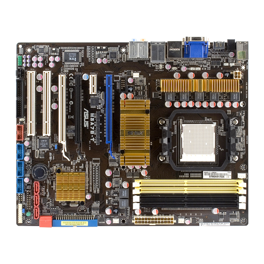
Page 27: Motherboard Layout
2.2.3 Motherboard layout Refer to 2.7 Connectors for more information about rear panel connectors and internal connectors. ASUS M3A78-T... -
Page 28: Layout Contents
2.2.4 Layout contents Slots DDR2 DIMM slots PCI slots PCI Express x1 slot PCI Express 2.0 x16 slot (blue) Universal PCI Express x16 slots (black and white) Jumper Clear RTC RAM (3-pin CLRTC) Rear panel connectors PS/2 keyboard / mouse combo port Video Graphics Adapter (VGA) port USB 2.0 ports 1 and 2 LAN (RJ-45) port. - Page 29 ATX power connectors (24-pin EATXPWR; 4-pin ATX12V) Front panel audio connector (10-1 pin AAFP) Optical drive audio connector (4-pin CD) Digital audio connector (4-1 pin SPDIF_OUT) System panel connector (20-8-pin PANEL) ASUS Q-Connector (system panel) ASUS M3A78-T Page 2-23 2-24...
-
Page 30: Central Processing Unit (Cpu)
Central Processing Unit (CPU) The motherboard comes with an AM2+/AM2 socket designed for AMD AM2+ Phenom™ FX / Phenom / Athlon™ / Sempron™ processors or for Socket Phenom™ FX / Phenom / Athlon™ / Sempron™ processors or for Socket AM2 Athlon series / Sempron processors. The AM2+/AM2 socket has a different pinout from the 940-pin socket designed for the AMD Opteron processor. - Page 31 CPU. The lever clicks on the side tab to indicate that it is locked. Install a CPU heatsink and fan following the instructions that came with the heatsink package. ASUS M3A78-T Gold triangle Small triangle...
-
Page 32: Installing The Heatsink And Fan
2.3.2 Installing the heatsink and fan The AMD Phenom™ FX / Phenom / Athlon™/ Sempron™ processor requires a Phenom™ FX / Phenom / Athlon™/ Sempron™ processor requires a ® specially designed heatsink and fan assembly to ensure optimum thermal condition and performance. - Page 33 Push down the retention bracket lock on the retention mechanism to secure the heatsink and fan to the module base. ASUS M3A78-T...
- Page 34 When the fan and heatsink assembly is in place, connect the CPU fan cable to the connector on the motherboard labeled CPU_FAN. • Do not forget to connect the CPU fan connector! Hardware monitoring errors can occur if you fail to plug this connector. •...
-
Page 35: System Memory
The motherboard comes with four Double Data Rate 2 (DDR2) Dual Inline Memory Modules (DIMM) sockets. The figure illustrates the location of the DDR2 DIMM sockets: Channel Channel A Channel B ASUS M3A78-T Sockets DIMM_A1 and DIMM_A2 DIMM_B1 and DIMM_B2 2-11... -
Page 36: Memory Configurations
2.4.2 Memory configurations You may install 512 MB, 1 GB, and 2 GB unbuffered ECC and non-ECC DDR2 DIMMs into the DIMM sockets. Recommended Memory Configurations Mode Single-Channel Dual-channel (1) Dual-channel (2) • You may install varying memory sizes in Channel A and Channel B. The system maps the total size of the lower-sized channel for the dual-channel configuration. -
Page 37: Installing A Dimm
Support the DIMM lightly with your fingers when pressing the retaining clips. The DIMM might get damaged when it flips out with extra force. Remove the DIMM from the socket. ASUS M3A78-T DIMM notch Unlocked retaining clip DIMM notch 2-13... -
Page 38: Expansion Slots
Expansion slots In the future, you may need to install expansion cards. The following sub-sections describe the slots and the expansion cards that they support. Make sure to unplug the power cord before adding or removing expansion cards. Failure to do so may cause you physical injury and damage motherboard components. -
Page 39: Interrupt Assignments
– USB 1.0 controller 2 – USB 1.0 controller 3 – USB 1.0 controller 4 – USB 2.0 controller – HD audio shared Onboard SATA – ASUS M3A78-T – – – – – shared – – – shared – –... -
Page 40: Pci Slots
2.5.4 PCI slots The PCI slots support cards such as a LAN card, SCSI card, USB card, and other cards that comply with PCI specifications. Refer to the figure below for the location of the slots. 2.5.5 PCI Express x1 slot This motherboard supports PCI Express x1 network cards, SCSI cards and other cards that comply with the PCI Express specifications. - Page 41 CHA_FAN1 or CHA_FAN2 for better thermal environment. See page 2-28 for the connector location. • Visit the AMD official website at www.amd.com for more information about Hybrid CrossFireX™ support. ASUS M3A78-T PCI Express operating mode PCIex16_1 PCIex16_2 Vista operation system supports Hybird ®...
-
Page 42: Jumper
Jumper Clear RTC RAM (3-pin CLRTC) This jumper allows you to clear the Real Time Clock (RTC) RAM in CMOS. You can clear the CMOS memory of date, time, and system setup parameters by erasing the CMOS RTC RAM data. The onboard button cell battery powers the RAM data in CMOS, which include system setup information such as system passwords. -
Page 43: Connectors
4-channel, 6-channel, and 8-channel configuration, the function of this port becomes Front Speaker Out. Microphone port (pink). This port connects a microphone. 10. Side Speaker Out port (gray). This port connects the side speakers in an 8-channel audio configuration. ASUS M3A78-T 88E1116 Gigabit LAN controller, ® Speed LED Status... - Page 44 Refer to the audio configuration table on the next page for the function of the audio ports in 2, 4, 6, or 8-channel configuration. Audio 2, 4, 6, or 8-channel configuration Headset Port 2-channel Light Blue Line In Lime Line Out Pink Mic In Orange...
- Page 45 Optical S/PDIF Out port. This port connects an external audio output device via an optical S/PDIF cable. 17. USB 2.0 ports 5 and 6. These 4-pin Universal Serial Bus (USB) ports are available for connecting USB 2.0 devices. ASUS M3A78-T 2-21...
-
Page 46: Troubleshooting On Hdtv Overscaling Or Underscaling
Troubleshooting on HDTV overscaling or underscaling: If your desktop is extending beyond the viewable display area or the desktop or image is not filling the entire display area while using the onboard HDMI out port and the HDMI cable, you can resize the desktop appearing on your HDTV screen. To resize your HDTV desktop: Install AMD Chipset Driver from the motherboard support DVD. -
Page 47: Internal Connectors
Pin 5 on the connector is removed to prevent incorrect cable connection when using a FDD cable with a covered Pin 5. ASUS M3A78-T 2-23... - Page 48 IDE connector (40-1 pin PRI_IDE) The onboard IDE connector is for the Ultra DMA 133/100/66/33 signal cable. There are three connectors on each Ultra DMA 133/100/66/33 signal cable: blue, black, and gray. Connect the blue connector to the motherboard’s IDE connector, then select one of the following modes to configure your device.
- Page 49 SATA device. Or you may connect the right-angle side of SATA cable to the onboard SATA port to avoid mechanical conflict with huge graphics cards. ASUS M3A78-T XP Service Pack 1 before using Serial ATA. ® right angle side...
- Page 50 Never connect a 1394 cable to the USB connectors. Doing so will damage the motherboard! You can connect the front panel USB cable to the ASUS Q-Connector (USB, blue) first, and then install the Q-Connector (USB) to the USB connector onboard if your chassis supports front panel USB ports.
- Page 51 Never connect a USB cable to the IEEE 1394a connector. Doing so will damage the motherboard! You can connect the front panel 1394 cable to the ASUS Q-Connector (1394, red) first, and then install the Q-Connector (1394) to the 1394 connector onboard if your chassis supports front panel 1394 ports.
- Page 52 Do not place jumper caps on the fan connectors! • Only the CPU_FAN, CHA_FAN1 and CHA_FAN2 connectors support the ASUS Q-Fan 2 feature. • If you install two graphics cards, we recommend that you plug the rear chassis fan cable to the motherboard connector labeled CHA_FAN1 or CHA_FAN2 for better thermal environment.
- Page 53 By default , the pin labeled “Chassis Signal” and “Ground” are shorted with a jumper cap. Remove the jumper caps only when you intend to use the chassis intrusion detection feature. ASUS M3A78-T 2-29...
- Page 54 • If you are uncertain about the minimum power supply requirement for your system, refer to the Recommended Power Supply Wattage Calculator at http://support.asus.com/PowerSupplyCalculator/PSCalculator. aspx?SLanguage=en-us for details. • The ATX 12 V Specification 2.0-compliant (500W) PSU has been tested...
- Page 55 Front Panel Support Type item in the BIOS setup to [HD Audio]; if you want to connect an AC'97 front panel audio module to this connector, set the item to [AC97]. By default, this connector is set to [HD Audio]. ASUS M3A78-T 2-31...
- Page 56 10. Optical drive audio connector (4-pin CD) These connectors allow you to receive stereo audio input from sound sources such as a CD-ROM, TV tuner, or MPEG card. 11. Digital audio connector (4-1 pin SPDIF_OUT) This connector is for an additional Sony/Philips Digital Interface (S/PDIF) port(s).
-
Page 57: System Panel Connector
BIOS settings. Pressing the power switch for more than four seconds while the system is ON turns the system OFF. • Reset button (2-pin RESET) This 2-pin connector is for the chassis-mounted reset button for system reboot without turning off the system power. ASUS M3A78-T 2-33... - Page 58 2-34 Chapter 2: Hardware information...
-
Page 59: Chapter 3: Powering Up
This chapter describes the power up sequence, the vocal POST messages, Chapter 3: and ways of shutting down the system. Powering up... -
Page 60: Starting Up For The First Time
Chapter summary Starting up for the first time ... 3-1 Turning off the computer ... 3-2 ASUS M3A78-T... -
Page 61: Starting Up For The First Time
One continuous beep followed by three short beeps One continuous beep followed by four short beeps At power on, hold down the <Delete> key to enter the BIOS Setup.. ASUS M3A78-T Description No keyboard detected No memory detected No VGA detected... -
Page 62: Turning Off The Computer
Turning off the computer 3.2.1 Using the OS shut down function If you are using Windows Click the Start button then select Turn Off Computer. Click the Turn Off button to shut down the computer. The power supply should turn off after Windows If you are using Windows Click the Start button then select ShutDown. -
Page 63: Chapter 4: Bios Setup
This chapter tells how to change the system settings through the BIOS Setup menus. Detailed descriptions of the BIOS Chapter 4: parameters are also provided. BIOS setup... - Page 64 Chapter summary Managing and updating your BIOS ... 4-1 BIOS setup program ... 4-9 Main menu ... 4-12 Advanced menu ... 4-17 Power menu ... 4-31 Boot menu ... 4-35 Tools menu ... 4-39 Exit menu ... 4-42 ASUS M3A78-T...
-
Page 65: Managing And Updating Your Bios
The following utilities allow you to manage and update the motherboard Basic Input/Output System (BIOS) setup. ASUS EZ Flash 2 (Updates the BIOS using a floppy disk, USB Flash, or the motherboard support DVD during POST.) ASUS AFUDOS (Updates the BIOS in DOS mode using a bootable floppy disk.) -
Page 66: Creating A Bootable Floppy Disk
4.1.1 Creating a bootable floppy disk Do either one of the following to create a bootable floppy disk. DOS environment a. Insert a 1.44MB floppy disk into the drive. b. At the DOS prompt, type format A:/S then press <Enter>. Windows XP environment ®... -
Page 67: Asus Ez Flash 2 Utility
4.1.2 ASUS EZ Flash 2 utility The ASUS EZ Flash 2 feature allows you to update the BIOS without having to go through the long process of booting from a floppy disk and using a DOS-based utility. The EZ Flash 2 utility is built-in the BIOS chip so it is accessible by pressing <Alt>... -
Page 68: Afudos Utility
Main filename Press <Enter>. The utility copies the current BIOS file to the floppy disk. A:\>afudos /oOLDBIOS1.rom AMI Firmware Update Utility - Version 1.19(ASUS V2.07(03.11.24BB)) Copyright (C) 2002 American Megatrends, Inc. All rights reserved. Reading flash ... done Write to file... ok A:\>... -
Page 69: Updating The Bios File
Updating the BIOS file To update the BIOS file using the AFUDOS utility: Visit the ASUS website (www.asus.com) and download the latest BIOS file for the motherboard. Save the BIOS file to a bootable floppy disk. Write the BIOS filename on a piece of paper. You need to type the exact BIOS filename at the DOS prompt. -
Page 70: Asus Update Utility
4.1.4 ASUS Update utility The ASUS Update is a utility that allows you to manage, save, and update the motherboard BIOS in Windows • Save the current BIOS file • Download the latest BIOS file from the Internet • Update the BIOS from an updated BIOS file •... - Page 71 Updating the BIOS through the Internet To update the BIOS through the Internet: Launch the ASUS Update utility from the Windows > Programs > ASUS > ASUSUpdate > ASUSUpdate. The ASUS Update main window appears. Select Update BIOS from the Internet option from the drop-down menu, then click Next.
- Page 72 Updating the BIOS through a BIOS file To update the BIOS through a BIOS file: Launch the ASUS Update utility from the Windows > Programs > ASUS > ASUSUpdate > ASUSUpdate. The ASUS Update main window appears. Select Update BIOS from a file option from the drop-down menu, then click Next.
-
Page 73: Bios Setup Program
The BIOS setup screens shown in this section are for reference purposes only, and may not exactly match what you see on your screen. • Visit the ASUS website (www.asus.com) to download the latest BIOS file for this motherboard. ASUS M3A78-T... -
Page 74: Bios Menu Screen
• The BIOS setup screens shown in this chapter are for reference purposes only, and may not exactly match what you see on your screen. • Visit the ASUS website (www.asus.com) to download the latest BIOS information. 4.4.3 Navigation keys At the bottom right corner of a menu screen are the navigation keys for that particular menu. -
Page 75: Menu Items
Down> keys to display the other items on the screen. 4.2.9 General help At the top right corner of the menu screen is a brief description of the selected item. ASUS M3A78-T System Time [06:22:54] System Date [Fri 01/18/2008] Legacy Diskette A [1.44M, 3.5 in]... -
Page 76: Main Menu
Power Boot Tools Exit [17:41:19] [Thu 05/15/2008] [1.44M, 3.5 in.] [Not Detected] [Not Detected] [HDT722516DLA380] [ASUS CRW-5232A1] [Not Detected] [Not Detected] [Not Detected] [Not Detected] Use [ENTER]. [TAB], or [SHIFT-TAB] to select a field. Use [+] or [-] to configure system time. -
Page 77: Primary Ide Master/Slave
Configuration options: [Disabled] [Auto] PIO Mode [Auto] Selects the PIO mode. Configuration options: [Auto] [0] [1] [2] [3] [4] ASUS M3A78-T BIOS SETUP UTILITY Select the type of device connected to the system. -
Page 78: Sata1/2/3/4/5/6
DMA Mode [Auto] Selects the DMA mode. Configuration options: [Auto] [SWDMA0] [SWDMA1] [SWDMA2] [MWDMA0] [MWDMA1] [MWDMA2] [UDMA0] [UDMA1] [UDMA2] [UDMA3] [UDMA4] [UDMA5] [UDMA6] SMART Monitoring [Auto] Sets the Smart Monitoring, Analysis, and Reporting Technology. Configuration options: [Auto] [Disabled] [Enabled] 32Bit Data Transfer [Enabled] Enables or disables 32-bit data transfer. -
Page 79: Storage Configuration
OnChip SATA Type [IDE] This item appears only when you set the OnChip SATA Channel item to [Enabled] and allows you to set the OnChip SATA Type. Configuration options: [IDE] [RAID] [AHCI] ASUS M3A78-T BIOS SETUP UTILITY [Enabled] [IDE] Options... -
Page 80: System Information
• If you want to use the Serial ATA hard disk drives as Parallel ATA physical If you want to use the Serial ATA hard disk drives as Parallel ATA physical storage devices, keep the default setting [IDE]. • If you want the Serial ATA hard disk drives to use the Advanced Host Controller Interface (AHCI), set this item to [AHCI]. -
Page 81: Advanced Menu
Allows you to individually set overclocking parameters. Auto Loads the optimal settings for the system. Standard Loads the standard settings for the system.performance. Overclock Profile Loads overclocking profiles with optimal parameters for stability when overclocking. ASUS M3A78-T BIOS SETUP UTILITY Boot Tools Exit [Auto] [Auto] [Auto]... - Page 82 The following item appears only when you set the Ai Overclocking item to [Overclock Profile]. Overclock Options [Disabled] Allows you to set the overclocking options. Configuration options: [Disabled] [Overclock 3%] [Overclock 5%] [Overclock 10%] [Overclock 15%] [Overclock 20%] [Overclock 30%] The following two items appear only when you set the Ai Overclocking item to [Manual].
- Page 83 You can enter the desired Core/PCIe voltage using the numeric keypad. The values range from 1.10V to 1.60V with a 0.02V interval. CPU Tweak [Enabled] Allows you to enable or disable the CPU Tweak feature. Configuration options: [Enabled] [Disabled] ASUS M3A78-T 4-19...
-
Page 84: Dram Timing Configuration
DRAM Timing Configuration Advanced DRAM Timing Configuration Memory Clock Mode 2T Mode DRAM Timing Mode The configuration options for some of the following items vary depending on the DIMMs you install on the motherboard. Memory Clock Mode [Auto] Allows selection of the DRAM Frequency programming method. Configuration options: [Auto] [Limit] [Manual] Memclock Value [400 MHz] This sub-item appears only when you set the Memory Clock Mode item to... -
Page 85: Ai Net 2
LAN (RJ-45) port. Advanced AI NET 2 Pair Status Length 1-2 N/A Realtek Controller 0 3-6 N/A 4-5 N/A 7-8 N/A Marvell POST Check LAN cable [Disabled] ASUS M3A78-T BIOS SETUP UTILITY Check Realtek LAN cable during POST. 4-21... -
Page 86: Cpu Configuration
Marvell POST Check LAN cable [Disabled] Allows you to enable or disable LAN cable check during POST. When enabled, the menu reports the cable faults or shorts, and displays the point (length) where the faults or shorts are detected. Configuration options: [Disabled] [Enabled] 4.4.3 CPU Configuration Advanced... -
Page 87: Chipset
Use the <+> and <-> keys to change the value or type the desired value using the numeric keypad. The values range from 0 to 255. Port #02/03 Features Gen2 High Speed Mode [Disabled] Configuration options: [Auto] [Disabled] [Software Initiated] [Advertised RC] ASUS M3A78-T BIOS SETUP UTILITY PCI Express Configuration [25] 4-23... -
Page 88: Internal Graphics Configuration
Link ASPM [Disabled] Configuration options: [Disabled] [L0s] [L1] [L0s & L1] Link Width [Auto] Configuration options: [Auto] [x1] [x2] [x4] [x8] [x16] Slot Power Limit, W [75] Use the <+> and <-> keys to change the value or type the desired value using the numeric keypad. - Page 89 If you set the PCI Express device as the primary display and enable this item, you may use the internal graphics as the secondary display. Configuration options: [Disabled] [Enable] NB Azalia [Enable] Enables or disables the Northbridge Azalia support. Configuration options: [Disabled] [Enable] ASUS M3A78-T 4-25...
-
Page 90: Ecc Configuration
4.4.5 ECC Configuration Advanced ECC Configuration ECC Mode DRAM ECC Enable DRAM SCRUB REDIRECT 4-Bit ECC Mode DRAM BG Scrub Data Cache BG Scrub L2 Cache BG Scrub L3 Cache BG Scrub ECC Mode [Disabled] Disables or sets the DRAM ECC mode that allows the hardware to report and correct memory errors. - Page 91 Disables or sets the L2/L3 Cache BG Scrub. This item allows the L2/L3 Data Cache RAM to be corrected when idle. Configuration options: [Disabled] [40ns] [80ns] [160ns] [320ns] [640ns] [1.28us] [2.56us] [5.12us] [10.2us] [20.5us] [41.0us] [81.9us] [163.8us] [327.7us] [655.4us] [1.31ms] [4.62ms] [5.24ms] [10.49ms] [20.97ms] [42.00ms] [84.00ms] ASUS M3A78-T 4-27...
-
Page 92: Onboard Devices Configuration
4.4.6 Onboard Devices Configuration Advanced Onboard Devices Configuraiton Serial Port1 Address HD Audio Azalia Device Front Panel Support Type SPDIF_OUT Mode Setting Onboard 1394 Onboard Marvell Lan Onboard Marvell LAN Boot ROM [Disabled] Primary Display Adapter Serial Port1 Address [3F8/IRQ4] Allows you to select the Serial Port1 base address. -
Page 93: Pci Pnp
When set to [Enabled], the palete snooping feature informs the PCI devices that an ISA graphics device is installed in the system so that the latter can function correctly. Configuration options: [Disabled] [Enabled] ASUS M3A78-T BIOS SETUP UTILITY [No] [64]... -
Page 94: Usb Configuration
IRQ-xx assigned to [PCI Device] When set to [PCI Device], the specific IRQ is free for use of PCI/PnP devices. When set to [Reserved], the IRQ is reserved for legacy ISA devices. Configuration options: [PCI Device] [Reserved] 4.4.8 USB Configuration The items in this menu allows you to change the USB-related features. -
Page 95: Power Menu
Allows you to enable or disable the Advanced Configuration and Power Interface (ACPI) support in the Application-Specific Integrated Circuit (ASIC). When set to Enabled, the ACPI APIC table pointer is included in the RSDT pointer list. Configuration options: [Disabled] [Enabled] ASUS M3A78-T BIOS SETUP UTILITY Boot Tools... -
Page 96: Apm Configuration
4.5.5 APM Configuration Power Button Mode Power On By PCI devices Power On By PCIE Devices Power On By External Modems Power On By RTC Alarm Power On By PS/2 Keyboard Power On By PS/2 Mouse Restore on AC Power Loss Power Button Mode [On/Off] Allows you to set the power button function. - Page 97 When set to Power On, the system goes on after an AC power loss. When set to Last State, the system goes into either off or on state, whatever the system state was before the AC power loss. Configuration options: [Power Off] [Power On] [Last State] ASUS M3A78-T 4-33...
-
Page 98: Hardware Monitor
Select [Ignored] if you do not want to detect this item. Smart Q-Fan Function [Disabled] Allows you to enable or disable the ASUS Q-Fan feature that smartly adjusts the fan speeds for more efficient system operation. Configuration options: [Disabled] [Enabled] The following items appear only if you set the Smart Q-Fan Function to [Enabled]. -
Page 99: Boot Menu
These items specify the boot device priority sequence from the available devices. The number of device items that appears on the screen depends on the number of devices installed in the system. Configuration options: [1st FlOPPY DRIVE] [Hard Drive] [ATAPI DVD-ROM] [Disabled] ASUS M3A78-T BIOS SETUP UTILITY Boot Tools Exit... -
Page 100: Boot Settings Configuration
This allows you to enable or disable the full screen logo display feature. Configuration options: [Disabled] [Enabled] Set this item to [Enabled] to use the ASUS MyLogo 2™ feature. Add On ROM Display Mode [Force BIOS] Sets the display mode for option ROM. -
Page 101: Security
Real Time Clock (RTC) RAM. See section 1.9 Jumpers for information on how to erase the RTC RAM. After you have set a supervisor password, the other items appear to allow you to change other security settings. ASUS M3A78-T BIOS SETUP UTILITY Boot <Enter> to change password. -
Page 102: Change User Password
Security Settings Supervisor Password User Password Change Supervisor Password User Access Level Change User Password Clear User Password Password Check User Access Level [Full Access] This item allows you to select the access restriction to the Setup items. Configuration options: [No Access] [View Only] [Limited] [Full Access] No Access prevents user access to the Setup utility. -
Page 103: Tools Menu
(C)Copyright 1985-2008, American Megatrends, Inc. 4.7.1 ASUS EZ Flash 2 Allows you to run ASUS EZ Flash 2. When you press <Ok>, a confirmation message appears. Use the left/right arrow key to select between [Yes] or [No], then press <Ok> to confirm your choice. -
Page 104: Express Gate
Express Gate Boot Out Timer Reset User Data You have to install the ASUS Express Gate application from the support DVD first before you can enable this feature. See page 3-5 for details. Express Gate [Enabled] Allows you to enable or disable the ASUS Express Gate feature. ASUS Express Gate is a unique instant-on environment that provides quick access to the Internet browser and Skype. -
Page 105: Asus O.c. Profile
4.7.3 ASUS O.C. Profile This item allows you to store or load multiple BIOS settings. O.C. PROFILE Configuration O.C. Profile 1 Status : Not Installed O.C. Profile 2 Status : Not Installed Save to Profile 1 Load from Profile 1... -
Page 106: Exit Menu
Exit menu The Exit menu items allow you to load the optimal or failsafe default values for the BIOS items, and save or discard your changes to the BIOS items. Exit Options Exit & Save Changes Exit & Discard Changes Discard Changes Load Setup Defaults Pressing <Esc>... -
Page 107: Chapter 5: Software Support
This chapter describes the contents of the support DVD that comes with the motherboard package. Chapter 5: Software support... - Page 108 Chapter summary Installing an operating system ... 5-1 Support DVD information ... 5-1 Software information ... 5-9 RAID configurations ... 5-44 Creating a RAID driver disk ... 5-51 ASUS M3A78-T...
-
Page 109: Installing An Operating System
The contents of the support DVD are subject to change at any time without notice. Visit the ASUS website(www.asus.com) for updates. 5.2.1 Running the support DVD Place the support DVD to the optical drive. The DVD automatically displays the Drivers menu if Autorun is enabled in your computer. -
Page 110: Drivers Menu
The drivers menu shows the available device drivers if the system detects installed devices. Install the necessary drivers to activate the devices. ASUS InstAll - Installation Wizard for Anti-Virus and drivers Installs all of the drivers and the Anti-Virus utility through the installation wizard. -
Page 111: Utilities Menu
Utilities menu The Utilities menu shows the applications and other software that the motherboard supports. ASUS InstAll - Installation Wizard for Utilities Installs all of the utilities through the Installation Wizard. AMD OverDrive Utility (AOD) Installs the AMD OverDrive utility. - Page 112 This item installs the ASUS Cool‘n’Quiet utility. ASUS Update Allows you to download the latest version of the BIOS from the ASUS website. Before using the ASUS Update, make sure that you have an Internet connection so you can connect to the ASUS website.
-
Page 113: Make Disk Menu
® 5.2.4 Make Disk menu The Make Disk menu contains items to create the ATI force™ RAID/AHCI driver ® disk. ATI RAID/AHCI 32/64bit WinXP/Vista Driver Allows you to create ATI RAID/AHCI driver disks for 32/64bit Windows XP/Vista. ® ASUS M3A78-T... -
Page 114: Manual Menu
5.2.6 ASUS Contact information Click the Contact tab to display the ASUS contact information. You can also find this information on the inside front cover of this user guide. Reader from the Utilities menu before opening a user manual ®... -
Page 115: Other Information
The icons on the top right corner of the screen give additional information on the motherboard and the contents of the support DVD. Click an icon to display the specified information. Motherboard Info Displays the general specifications of the motherboard. Browse this DVD Displays the support DVD contents in graphical format. ASUS M3A78-T... -
Page 116: Technical Support Form
Technical support Form Displays the ASUS Technical Support Request Form that you have to fill out when requesting technical support. File list Displays the contents of the support DVD and a brief description of each in text format. Chapter 5: Software support... -
Page 117: Software Information
5.3.1 ASUS MyLogo2™ The ASUS MyLogo2™ utility lets you customize the boot logo. The boot logo is the image that appears on screen during the Power-On Self-Tests (POST). The ASUS MyLogo2™ is automatically installed when you install the ASUS Update utility from the support DVD. - Page 118 Ratio box. When the screen returns to the ASUS Update utility, flash the original BIOS to load the new boot logo. 10. After flashing the BIOS, restart the computer to display the new boot logo during POST.
-
Page 119: Cool 'N' Quiet!™ Technology
Double-click the Display icon in the Control Panel then select the Screen Saver tab. Click the Power button. The following dialogue box appears. From the Power schemes combo list box, select Minimal Power Management. Click OK to effect settings. ASUS M3A78-T 5-11... - Page 120 The AMD Cool ‘n’ Quiet!™ technology feature works only with the AMD heatsink and fan assembly with monitor chip • If you purchased a separate heatsink and fan package, use the ASUS Q-Fan technology feature to automatically adjust the CPU fan speed according to your system loading.
- Page 121 ASUS > Cool & Quiet > Cool & Quiet. If you are using Windows > ASUS > Cool & Quiet > Cool & Quiet. The Cool ‘n’ Quiet!™ technology screen appears and displays the current CPU Frequency and CPU Voltage.
-
Page 122: Audio Configurations
5.3.3 Audio configurations The Realtek audio CODEC provides 8-channel audio capability to deliver the ® ultimate audio experience on your computer. The software provides Jack-Sensing function, S/PDIF Out support, and interrupt capability. The CODEC also includes the Realtek proprietary UAJ ®... -
Page 123: Connector Settings
Click any of the tabs in this area to configure your audio settings. In the Windows Vista™ environment, Realtek HD Audio Manager automatically detects devices connected to the analog/digital ports and shows corresponding configuration options tabs. ASUS M3A78-T ) to ) to exit the Realtek HD Audio 5-15... - Page 124 Digital Output The Realtek ® audio CODEC allows you to connect an external audio output device via the coaxial/digital S/PDIF port. You can set your listening environment, set the karaoke, or select pre-programmed equalizer settings for your listening pleasure. To set the digital output options From the Realtek HD Audio Manager, click the Digital Output tab.
- Page 125 Acoustic Echo Cancellation option button to reduce the echo from the front speakers when recording. Click the Beam Forming option button to eliminate surrounding noise interferences. Click the Default Format sub-tab for options on changing the default audio input format. Click to effect the Microphone settings and exit. ASUS M3A78-T 5-17...
- Page 126 Realtek HD Audio Manager for Windows XP™ Configuration options Control settings window Information button Information Click the information button ( display information about the audio driver version, DirectX version, audio controller, audio codec, and language setting. Minimize Click the minimize button ( Exit Click the exit button ( 5-18...
-
Page 127: Configuration Options
Click the next button ( Click to effect the Mixer settings and exit. ASUS M3A78-T ) if you do not want voice input. ) to display more menu options. 5-19... - Page 128 Audio I/O The Audio I/O option allows you configure your input/output settings. To set the Audio I/O options From the Realtek HD Audio Manager, click the Audio I/O tab. Click the drop-down menu to select the channel configuration. The control settings window displays the status of connected devices.
- Page 129 From the Realtek HD Audio Manager, click the 3D Audio Demo tab. Click the option buttons to change the sound, moving path, or environment settings. Click to test your settings. Click to effect the 3D Audio Demo settings and exit. ASUS M3A78-T 5-21...
-
Page 130: Asus Pc Probe Ii
® To launch the PC Probe II from the Windows > ASUS > PC Probe II > PC Probe II v1.xx.xx. The PC Probe II main window appears. After launching the application, the PC Probe II icon appears in the Windows taskbar. - Page 131 When displayed, the monitor panel for that sensor also turns red. Refer to the Monitor panels section for details. Preference You can customize the application using the Preference section in the main window. Click the box before each preference to activate or deactivate. ASUS M3A78-T 5-23...
- Page 132 Hardware monitor panels The hardware monitor panels display the current value of a system sensor such as fan rotation, CPU temperature, and voltages. The hardware monitor panels come in two display modes: hexagonal (large) and rectangular (small). When you check the Enable Monitoring Panel option from the Preference section, the monitor panels appear on your computer’s desktop.
- Page 133 DMI browser Click to display the DMI (Desktop Management Interface) browser. This browser displays various desktop and system information. Click the plus sign (+) before DMI Information to display the available information. ASUS M3A78-T Small display 5-25...
- Page 134 PCI browser Click to display the PCI (Peripheral Component Interconnect) browser. This browser provides information on the PCI devices installed on your system. Click the plus sign (+) before the PCI Information item to display available information. Usage The Usage browser displays real-time information on the CPU, hard disk drive space, and memory usage.
- Page 135 The Preference tab allows you to customize sensor alerts, or change the temperature scale. Loads the default threshold values for each sensor Applies your changes ASUS M3A78-T Loads your saved Cancels or configuration ignores your changes Saves your configuration...
-
Page 136: Asus Ai Suite
5.3.5 ASUS AI Suite ASUS AI Suite allows you to launch AI Gear 2, AI Booster, AI Nap, and Q-Fan 2 utilities easily. Installing AI Suite To install AI Suite on your computer: Place the support DVD to the optical drive. The Drivers installation tab appears if your computer has an enabled Autorun feature. - Page 137 Click on right corner of the expanded window to switch the temperature from degrees Centigrade to degrees Fahrenheit. ASUS M3A78-T Displays the CPU/ system temperature, CPU/memory/PCIE voltage, and CPU/...
-
Page 138: Asus Ai Gear 2
5.3.6 ASUS AI Gear 2 ASUS AI Gear 2 provides four system performance options that allows you to select the best performance setting for your computing needs. This easy-to-use utility adjusts the processor frequency and vCore voltage to minimize system noise and power consumption. -
Page 139: Asus Ai Nap
5.3.7 ASUS AI Nap This feature allows you to minimize the power consumption of your computer whenever you are away. Enable this feature for minimum power consumption and a more quiet system operation. After installing AI Suite from the bundled support DVD, you can launch the utility by double-clicking the AI Suite icon on the Windows OS taskbar and click the AI Nap button on the AI Suite main window. -
Page 140: Asus Q-Fan 2
5.3.8 ASUS Q-Fan 2 This ASUS Q-Fan 2 Control feature allows you to set the appropriate performance level of the CPU Q-Fan 2 or the Chassis Q-Fan 2 for more efficient system operation. After enabling the Q-Fan 2 function, the fans can be set to automatically adjust depending on the temperature, to decrease fan speed, or to achieve the maximum fan speed. -
Page 141: Asus Ai Booster
5.3.9 ASUS AI Booster The ASUS AI Booster application allows you to overclock the CPU speed in WIndows environment without the hassle of booting the BIOS. ® After installing AI Suite from the bundled support DVD, you can launch the utility... -
Page 142: Asus Express Gate
5.3.10 ASUS Express Gate ASUS Express Gate is an instant-on environment that gives you quick access to the Internet. Within a few seconds of powering on your computer, you will be at the Express Gate menu where you can start the web browser, Skype, or other Express Gate softwares. - Page 143 The very first time you enter the Express Gate environment (by launching either web or Skype from the first screen), a first time wizard will guide you through basic Express Gate configurations. Basic configurations include language, date and time and screen resolution. ASUS M3A78-T 5-35...
- Page 144 Once inside the Express Gate environment, click on the icons on the LaunchBar, by default at bottom of the screen, to launch or switch between softwares. You can re-arrange, re-size and move windows. Bring a window to the foreground by clicking within it or by clicking on its corresponding software icon. Re-size a window by dragging any of its four corners.
-
Page 145: Using The Configuration Panel
Express Gate to finish clearing the settings. This is also useful in the rare case where settings might become corrupted. The first-time Wizard will run again when you enter the Express Gate environment after clearing its settings. ASUS M3A78-T 5-37... -
Page 146: Using The Launchbar
USB drive. If a USB device is detected, the icon contains a green arrow. ASUS Express Gate supports file uploading from SATA HDDs, ODDs and USB drive and downloading to USB drives only. Shows network status; click to configure network. - Page 147 Click to choose input language and method as well as keyboard shortcuts (Ctrl-Space by default). Click to change LaunchBar options (auto-hide, docking position, etc). Click to show the “ASUS Utility” panel. Click to show “About Express Gate ”. Click to open Express Gate Help.
- Page 148 Open Network. Network Make the proper network configurations. Each network interface is enabled immediately when you check the box next to it. • If you use a network cable connected to a home router (which is then connected to your DSL/cable modem), enable both LAN1 and LAN2. Express Gate will automatically use whichever port (LAN1 or LAN2) is connected.
- Page 149 Shows user- created image album(s) ASUS Express Gate supports HDDs connected to motherboard chipset- controlled onboard SATA ports only. All onboard extended SATA ports and external SATA ports are NOT supported. ASUS M3A78-T Help View mode...
-
Page 150: Updating Express Gate
Express Gate software will be released regularly, adding refinements or new applications. You can find original version of the software on the support DVD or download new versions from the ASUS support website. To update Express Gate Double-click the Express Gate setup file to start software update. -
Page 151: Amd Overdrive (Aod)
Some advanced options in AOD are only supported by certain AMD Black Edition CPUs (such as Phenom 9600 Black Edition, Phenom 9850 Black Edition and Phenom 9950 Black Edition). visit the AMD official website at www.amd. com for CPU support lists. ASUS M3A78-T 5-43... -
Page 152: Raid Configurations
RAID configurations The motherboard comes with the AMD SB750 chipset that allows you to configure Serial ATA hard disk drives as RAID sets. The motherboard supports the following RAID configurations: RAID 0, RAID 1, RAID 5 and RAID 10. 5.4.1 RAID definitions RAID 0 (Data striping) optimizes two identical hard disk drives to read and write data in parallel, interleaved stacks. -
Page 153: Installing Serial Ata Hard Disks
In the Main Menu, go to Storage Configuration, and set the OnChip SATA Type item to [RAID]. Press <F10> to save the changes and exit. The RAID BIOS setup screens shown in this section are for reference only, and may not exactly match the items on your screen. ASUS M3A78-T 5-45... - Page 154 FastBuild™ Utility ® To enter the AMD FastBuild™ utility: ® Boot up your computer. Press <Ctrl+F> during POST to display the main menu of the utility. FastBuild (tm) Utility (c) 2004-2005 ATI Technology, Inc. Press 1..4 to Select Option The Main Menu above allows you to select an operation to perform. The Main Menu options include: View Drive Assignments: shows the status of the hard disk drives.
- Page 155 LD 5 ---- LD 6 ---- LD 7 ---- LD 8 ---- [ Keys Available ] [↑]Up [↓]Down [ESC]Exit ASUS M3A78-T Total Drv Fast Init: Cache Mode: WriteThru Capacity (MB) xxxxxx xxxxxx xxxxxx xxxxxx [Space] Change Option [Ctrl-Y]Save Capacity(MB) Status...
- Page 156 Creating a RAID 1 configuration To create a RAID 1 set: In the Main Menu, press <2> to enter the “Define LD” function. Press <Enter>, and the following screen appears. FastBuild (tm) Utility (c) 2004-2005 ATI Technology, Inc. LD No RAID Mode LD 1 RAID 1...
- Page 157 LD 5 ---- LD 6 ---- LD 7 ---- LD 8 ---- [ Keys Available ] [↑]Up [↓]Down [ESC]Exit ASUS M3A78-T Total Drv Fast Init: Cache Mode: WriteThru Capacity (MB) xxxxxx xxxxxx xxxxxx xxxxxx [Space] Change Option [Ctrl-Y]Save Capacity(MB) Status...
-
Page 158: Deleting A Raid Configuration
Deleting a RAID configuration To create a RAID set: In the Main Menu, press <3> to enter the “Delete LD” function. Select the RAID item you want to delete and press <Del> or <Alt+D>. FastBuild (tm) Utility (c) 2004-2005 ATI Technology, Inc. LD No RAID Mode LD 1... -
Page 159: Creating A Raid Driver Disk
Press <F6> then insert the floppy disk with RAID driver into the floppy disk drive. When prompted to select the SCSI adapter to install, make sure you select SB 750. Follow the succeeding screen instructions to complete the installation. ASUS M3A78-T ® ® ® 5-51... - Page 160 To install the RAID driver in Windows Insert the floppy disk/USB device with RAID driver into the floppy disk drive/ USB port. During the OS installation, select SB 750. Follow the succeeding screen instructions to complete the installation. 5-52 Vista™: ®...
-
Page 161: Chapter 6: Ati Hybrid Crossfirex™ Technology Support
This chapter describes the ATI Hybrid CrossFireX™ feature and shows the graphics card installation procedures. Hybrid CrossFireX™ ® technology support... - Page 162 Chapter summary 6.1 Hybrid CrossFireX™ ..6-1 ® ASUS M3A78-T...
-
Page 163: System Requirements
SIDEPORT Memory Voltage GFX Engine Clock Override UMA-SP Interleave Mode Surround View NB Azalia Press <F10> to save the changes and exit BIOS settings. Select OK to confirm. ASUS M3A78-T Hybrid CrossFire™ technology that allows you ® Vista ® [UMA+SIDEPORT] Auto... -
Page 164: Installing Amd Chipset Driver
6.1.3 Installing AMD Chipset Driver To install the driver that supports Hybrid CrossFireX technology: Insert the Support DVD that comes with your motherboard into the optical drive. The DVD automatically displays the Drivers menu if Autorun is enabled in your computer. If Autorun is NOT enabled in your computer, browse the contents of the support DVD to locate the file ASSETUP.EXE from the BIN folder. - Page 165 If you are using both an add-on and the on-board graphics cards at same time and want to set the onboard graphics card as your main monitor, follow the instructions on the next page. ASUS M3A78-T desktop, and then click ATI CATALYST(R) ®...
- Page 166 Follow steps 1 to 3 on Using the onboard graphics card. From the ATI CATALYST(R) Control Center screen, click Display Manager > Graphics Adapter. Select ATI Radeon HD 3200 Graphics [Gabbs, G HW173]. Click OK, and then Yes from the confirmation window. Follow steps 6 to step 8 on Using the onboard graphics card to complete the process of setting up...