Table of Contents
Advertisement
Quick Links
Advertisement
Table of Contents

Related Manuals for Asus A7A266


Summary of Contents for Asus A7A266
- Page 1 ® A7A266 DDR SDRAM 266MHz FSB AGP Pro/4X Socket A Motherboard USER’S MANUAL...
- Page 2 Product warranty or service will not be extended if: (1) the product is repaired, modified or al- tered, unless such repair, modification of alteration is authorized in writing by ASUS; or (2) the serial number of the product is defaced or missing.
-
Page 3: Asus Contact Information
ASUS COMPUTER GmbH (Europe) Marketing Address: Harkortstr. 25, 40880 Ratingen, BRD, Germany Fax: +49-2102-442066 Email: sales@asuscom.de (for marketing requests only) Technical Support Hotline: MB/Others: +49-2102-9599-0 Notebook: +49-2102-9599-10 Fax: +49-2102-9599-11 Support (Email): www.asuscom.de/de/support (for online support) WWW: www.asuscom.de FTP: ftp.asuscom.de/pub/ASUSCOM ASUS A7A266 User’s Manual... -
Page 4: Table Of Contents
1. INTRODUCTION 1.1 How This Manual Is Organized ... 7 1.2 Item Checklist ... 7 2. FEATURES 2.1 The ASUS A7A266 ... 8 2.1.1 Specifications ... 8 2.1.2 Optional Components ... 9 2.1.3 Special Features ... 10 2.1.4 Performance Features ... 10 2.1.5 Intelligence ... - Page 5 4.7 Exit Menu ... 76 5. SOFTWARE SETUP 5.1 Install Operating System ... 79 5.2 Start Windows ... 79 5.3 A7A266 Series Motherboard Support CD ... 80 6. SOFTWARE REFERENCE 6.1 ASUS PC Probe ... 81 6.2 CyberLink PowerPlayer SE ... 86 6.3 CyberLink VideoLive Mail ...
-
Page 6: Federal Communications Commission Statement
Radio Interference Regulations of the Canadian Department of Communications. This Class B digital apparatus complies with Canadian ICES-003. Cet appareil numérique de la classe B est conforme à la norme NMB-003 du Canada. ASUS A7A266 User’s Manual... -
Page 7: Introduction
(1) Ribbon cable for internal UltraDMA/33 IDE drives (1) Ribbon cable for one 5.25” and two 3.5” floppy disk drives (1) ASUS 2-port USB Connector Set (1) Bag of spare jumper caps (1) ASUS Support CD with drivers and utilities (1) This Motherboard User’s... -
Page 8: Features
2. FEATURES 2.1 The ASUS A7A266 The ASUS A7A266 motherboard is carefully designed for the value-conscious PC user who wants advanced features processed by the fastest processors. 2.1.1 Specifications ® • Athlon™/ Duron™ Processor Support: Supports AMD’s new socket- A Palomino™ / Thunderbird™ processor cores. -
Page 9: Optional Components
One Touch Management: Supports an optional ASUS iPanel, an easy to access box with system information LED display, front I/O ports, and space reserved for a hard disk drive. With an ASUS iPanel, you can monitor your computer system’s vital components. -
Page 10: Special Features
(SDRAM), which is compatible to the industry standard SDRAM. This new memory technology increases performance by executing two actions per clock cycle, resulting in data transfer rates of up to 2.1 GB/s for 133MHz DDR SDRAM and 1.6GB/s for 100MHz DDR SDRAM. ASUS A7A266 User’s Manual... -
Page 11: Intelligence
• Chassis Intrusion Detection: Supports chassis-intrusion monitoring through the ASUS ASIC. A chassis intrusion event is kept in memory on battery power for more protection. ASUS A7A266 User’s Manual... -
Page 12: Motherboard Components
USB Header (Port 2,3 & Port 4,5) ... 14 1 PS/2 Mouse Connector ... (Top) 27 1 PS/2 Keyboard Connector ... (Bottom) 27 1 ASUS IrDA/iPanel Connector ... (Right) 9 1 ASUS IR Connector ... (Left) 9 1 ASUS iPanel Audio Connector ... 21 Audio PCI Audio Chipset (optional) ... -
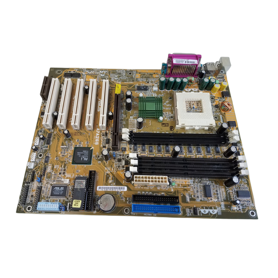
Page 13: Component Locations
2. FEATURES 2.2.1 Component Locations 10 9 ASUS A7A266 User’s Manual... -
Page 14: Hardware Setup
BCS2 PCI 2 PCI 3 PCI 4 WOL_CON PCI 5 Audio Modem Riser (AMR) Grayed components are available only on certain models at the time of purchase. ASUS A7A266 User’s Manual 24.5cm (9.64in) CPU_FAN JTPWR A7A266 FLOPPY M1535D+ Chipset CHASIS... -
Page 15: Layout Contents
38 Wake-On-LAN Connector (3 pin) 13) WOR p. 38 Wake-On-Ring Connector (2 pin) 14) CHA_FAN p. 39 Chassis, Power Supply, CPU Fan Connectors (3 pin) PWR_FAN CPU_FAN 15) USB1/USB2 p. 40 USB Headers (Two 10-1 pin) ASUS A7A266 User’s Manual continued... - Page 16 40 SMBus Connector (5-1 pin) 17) IrDA/AFPANEL p. 41 ASUS IrDA/iPanel Connector (24-1 pin) 18) AAPANEL p. 41 ASUS iPanel Audio Connector (12-1 pin) 19) CD1, AUX, MODEM p. 42 Internal Audio Connector (4 pin) 20) MIC2 p. 42 Internal Microphone Connector (3 pin) 21) PLED (PANEL) p.
-
Page 17: Getting Started
Before using your computer, you must complete the following steps: 1. Check Motherboard Settings 2. Install Memory Modules 3. Install the Central Processing Unit (CPU) 4. Install Expansion Cards 5. Connect Ribbon Cables, Panel Wires, and Power Supply 6. Setup the BIOS Software ASUS A7A266 User’s Manual... -
Page 18: Motherboard Settings
Failure to do so may cause severe damage to your motherboard, peripherals, and/or components. The onboard LED when lit acts as a reminder that the system is in suspend or soft-off mode and not powered OFF. A7A266 A7A266 Onboard LED ASUS A7A266 User’s Manual Standby Powered Power... - Page 19 DSWs come set to the OFF position and the JEN jumpers are set to [2-3]. Setting JumperFree [2-3] (default) Jumper Mode [1-2] A7A266 A7A266 Jumper Mode Setting ASUS A7A266 User’s Manual 1-10: Frequency Multiples OFF ON Jumper Mode Jumper Free (Default) OFF (Default)
- Page 20 3) DDR / SDR Memory Selection (DSW Switch 5) DSW switch 5 is OFF, for auto-detecting all settings using DDR RAM or SDRAM memory. DSW switch 5 is ON, for all settings using SDRAM memory. A7A266 A7A266 DDR/SDR DIMM Selection ASUS A7A266 User’s Manual Enable Disable (Default)
- Page 21 WARNING! Frequencies other than recommended CPU bus frequencies are not guaranteed to be stable. Overclocking your processor is not advised. It may result in a slower speed and premature wearing of the processor. ASUS A7A266 User’s Manual 100MHz 100MHz 120MHz...
- Page 22 DSW switch 10 is OFF to disable the manual CPU ratio settings. DSW switch 10 is ON, for all manual CPU ratio settings. A7A266 A7A266 CPU Ratio Setting Set DSW switches 6 through 9 as follows according to the desired multiplier: Multiplier 12.5x and up...
- Page 23 C-Media Audio Driver software setup available on the Support CD. These jumpers effectively swap the audio channels for bass and center. NOTE: the default setting is compatible with Creative 6-Channel audio speaker system. A7A266 A7A266 Jumper Mode Setting ASUS A7A266 User’s Manual 5.0x 5.5x 6.0x 6.5x...
-
Page 24: System Memory
Install memory in any combination as follows: DIMM Location 184-pin DDR DIMM Socket 1 (Rows 0&1) 64MB, 128MB, 256MB, 512MB, 1GB Socket 2 (Rows 2&3) 64MB, 128MB, 256MB, 512MB, 1GB Total System Memory (Max 2GB) ASUS A7A266 User’s Manual Total Memory... -
Page 25: Sdr Dimm Support
• DIMMs that have more than 18 chips are not supported on this motherboard. • ASUS motherboards support SPD (Serial Presence Detect) DIMMs. This is the memory of choice for best performance vs. stability. • BIOS shows SDRAM memory on bootup screen. -
Page 26: Memory Installation
The 184-pin DIMM must be a 2.5V unbuffered DDR SDRAM. Each DDR DIMM has a single notch slightly to the right of center: A7A266 A7A266 184-Pin DDR DIMM Sockets The 168-pin DIMM must be a 3.3V unbuffered SDR SDRAM. Look for two notches on each SDR DIMM:... -
Page 27: Central Processing Unit (Cpu)
Refer to heatsink/CPU documentation. NOTE! Do not forget to set the correct Bus Frequency and Multiple (available only on unlocked processors) to avoid start-up problems. ASUS A7A266 User’s Manual LEVER NOTCH LOCK AMD™ CPU... -
Page 28: Expansion Cards
4. Secure the card on the slot with the screw you removed above. 5. Replace the computer system’s cover. 6. Set up the BIOS if necessary (such as IRQ xx Used By ISA: Yes in 4.4.3 PCI Configuration) 7. Install the necessary software drivers for your expansion card. ASUS A7A266 User’s Manual... -
Page 29: Assigning Irqs For Expansion Cards
PCI slot 5 — AGP Pro slot shared Onboard PCI audio — Onboard USB controller — ASUS A7A266 User’s Manual Standard Function System Timer Keyboard Controller Programmable Interrupt Communications Port (COM2) Communications Port (COM1) Sound Card (sometimes LPT2) Floppy Disk Controller... -
Page 30: Accelerated Graphics Port Pro (Agp Pro)
3.7.3 Accelerated Graphics Port Pro (AGP Pro) This motherboard provides an Accelerated Graphics Port Pro (AGP Pro) slot to sup- port AGP/AGP Pro graphics cards, such as an ASUS AGP-V6800DDR/64M. CAUTION! To avoid damaging your AGP/AGP Pro graphics card, your computer’s power supply should be unplugged before inserting your graphics card into the slot. -
Page 31: Audio Modem Riser (Amr) Slot
For availability, see your vendor or dealer. A7A266 A7A266 Audio Modem Riser (AMR) Slot ASUS A7A266 User’s Manual ASUS MR-I Card... - Page 32 3. HARDWARE SETUP (This page was intentionally left blank.) ASUS A7A266 User’s Manual...
-
Page 33: Connectors
This connection is for a standard keyboard using an PS/2 plug (mini DIN). This connector will not allow standard AT size (large DIN) keyboard plugs. You may use a DIN to mini DIN adapter on standard AT keyboards. PS/2 Keyboard (6-pin Female) ASUS A7A266 User’s Manual... - Page 34 You can enable the parallel port and choose the IRQ through Onboard Parallel Port (see 4.4.2 I/O Device Configuration). NOTE: Serial printers must be connected to the serial port. Parallel Port (25-pin Female) ASUS A7A266 User’s Manual COM1 COM2 Serial Ports (9-pin Male)
- Page 35 (Pin 5 is removed to prevent inserting in the wrong orientation when using ribbon cables with pin 5 plugged). A7A266 A7A266 Floppy Disk Drive Connector ASUS A7A266 User’s Manual Game/MIDI (15-pin Female) Line Out Line In 1/8"...
- Page 36 IMPORTANT: UltraDMA100/66 IDE devices must use a 40-pin 80-conductor IDE cable for 100MB/s transfer rates. A7A266 A7A266 IDE Connectors ASUS A7A266 User’s Manual NOTE: Orient the red markings (usually zigzag) on the IDE ribbon cable to PIN 1. PIN 1...
- Page 37 The sensor is triggered when a high level signal is sent to the Chassis Signal lead, which occurs when a panel switch or light detector is triggered. This function works with an optional ASUS CIDB chassis intrusion module (see your vendor for more details). If the chassis intrusion lead is not used, a jumper cap must be placed over the pins to close the circuit.
- Page 38 12) Wake-On-LAN Connector (3-pin WOL_CON) This connector connects to a LAN card with a Wake-On-LAN output, such as the ASUS PCI-L101 Ethernet card (see 7. Appendix). The connector powers up the system when a wakeup packet or signal is received through the LAN card.
- Page 39 NOTE: The “Rotation” signal is to be used only by a specially designed fan with rotation signal. The Rotations per Minute (RPM) can be monitored using ASUS PC Probe (see 6. SOFTWARE REFERENCE). WARNING! The CPU and/or motherboard will overheat if there is no airflow across the CPU and onboard heatsinks.
- Page 40 2-port USB connector set and mount the bracket to an open slot on your chassis. A7A266 A7A266 Front Panel USB Headers 16) SMBus Connector (5-1 pin SMB) This connector allows you to connect SMBus (System Management Bus) devices.
- Page 41 I/O ports, status LEDs, and space reserved for a hard disk drive. If you are not using an ASUS iPanel, you can connect an optional wireless transmitting and receiving infrared module to the SIR connector or an optional consumer infrared connector set to the CIR and SIR connectors for both wireless transmitting and remote control functions through one external infrared module.
- Page 42 CD-ROM, TV tuner, or MPEG card. The MODEM connector allows the onboard audio to interface with a voice modem card with a similar connector A7A266 A7A266 Internal Audio Connectors 20) Internal Microphone Connector (3-pin MIC2) This connector allows you to connect a chassis mounted microphone to the motherboard instead of having to connect an external microphone to the Line Out connector on the back panel.
- Page 43 3. HARDWARE SETUP The following PANEL illustration is used for items 21-27 A7A266 A7A266 System Panel Connectors 21) System Power LED Lead (3-1 pin PLED) This 3-1 pin connector connects to the system power LED, which lights when the system is powered on and blinks when it is in sleep or soft-off mode.
- Page 44 ON your system if your power supply cannot support the load. For Wake-On- LAN support, your ATX power supply must supply at least 720mA +5VSB. A7A266 A7A266 ATX Power Connector 29) Power Supply Thermal Sensor Connector (2-pin block JTPWR) If you have a power supply with thermal monitoring, connect its thermal sensor cable to this connector.
-
Page 45: Starting Up The First Time
Long beeps in an endless loop One long beep followed by three short beeps High frequency beeps when system is working ASUS A7A266 User’s Manual Meaning No error during POST No DRAM installed or detected Video card not found or video card... - Page 46 Shut Down, and then click Shut down the computer? The power supply should turn off after Windows shuts down. NOTE: The message “You can now safely turn off your computer” will not appear when shutting down with ATX power supplies. ASUS A7A266 User’s Manual...
-
Page 47: Bios Setup
4. In DOS mode, type A:\AFLASH <Enter> to run AFLASH. IMPORTANT! If “unknown” is displayed after Flash Memory:, the memory chip is either not programmable or is not supported by the ACPI BIOS and therefore, cannot be programmed by the Flash Memory Writer utility. ASUS A7A266 User’s Manual... -
Page 48: Updating Bios Procedures
BIOS revision will solve your problems. Careless updating can result in your motherboard having more problems! 1. Download an updated ASUS BIOS file from the Internet (WWW or FTP) (see ASUS CONTACT INFORMATION on page 3 for details) and save to the disk you created earlier. - Page 49 NOTE: When you see the message “Boot Block is different”, you may still press <Y> to update the BIOS. Yet if the update fails, your system will run a greater risk of boot failure depending on whether the boot block is damaged or not. ASUS A7A266 User’s Manual...
- Page 50 BIOS file you saved to disk above. If the Flash Memory Writer utility was not able to successfully update a complete BIOS file, your system may not be able to boot up. If this happens, your system will need servicing. ASUS A7A266 User’s Manual...
-
Page 51: Bios Setup Program
POST. NOTE: Because the BIOS software is constantly being updated, the following BIOS screens and descriptions are for reference purposes only and may not re- flect your BIOS screens exactly. ASUS A7A266 User’s Manual... -
Page 52: Bios Menu Bar
Brings up a selection menu for the highlighted field <Home> or <PgUp> Moves the cursor to the first field <End> or <PgDn> Moves the cursor to the last field <F5> Resets the current screen to its Setup Defaults <F10> Saves changes and exits Setup ASUS A7A266 User’s Manual... -
Page 53: General Help
Setup program, note that explanations appear in the Item Specific Help window located to the right of each menu. This window displays the help text for the cur- rently highlighted field. NOTE: The item heading in square brackets represents the default setting for that field. ASUS A7A266 User’s Manual... -
Page 54: Main Menu
This is required to support older Japanese floppy drives. Floppy 3 Mode support will allow reading and writing of 1.2MB (as opposed to 1.44MB) on a 3.5-inch diskette. Configuration options: [Disabled] [Drive A] [Drive B] [Both] ASUS A7A266 User’s Manual... -
Page 55: Primary & Secondary Master/Slave
Primary IDE hard disk drives must have its partition set to active (also possible with FDISK). Other options for the Type field are: [None] - to disable IDE devices ASUS A7A266 User’s Manual... - Page 56 NOTE: To make changes to this field, the Type field must be set to [User Type HDD] and the Translation Method field must be set to [Manual]. ASUS A7A266 User’s Manual...
- Page 57 IDE devices. Set to [Disabled] to suppress Ultra DMA ca- pability. NOTE: To make changes to this field, the Type field must be set to [User Type HDD]. Configuration options: [0] [1] [2] [3] [4] [Disabled] ASUS A7A266 User’s Manual...
-
Page 58: Keyboard Features
[6/Sec] [8/Sec] [10/Sec] [12/Sec] [15/Sec] [20/Sec] [24/Sec] [30/Sec] Keyboard Auto-Repeat Delay [1/4 Sec] This field sets the time interval for displaying the first and second charac- ters. Configuration options: [1/4 Sec] [1/2 Sec] [3/4 Sec] [1 Sec] ASUS A7A266 User’s Manual... - Page 59 (2) Short the solder points, (3) Turn ON your computer, (4) Hold down <Delete> during bootup and enter BIOS setup to re-enter user preferences. A7A266 A7A266 Clear RTC RAM Halt On [All Errors] This field determines which types of errors will cause the system to halt.
-
Page 60: Advanced Menu
These fields allow you to choose from the default of [Enabled] or choose [Disabled] to turn on or off the CPU’s Level 1 and Level 2 built-in cache. Configuration options: [Disabled] [Enabled] ASUS A7A266 User’s Manual (When CPU Internal Frequency is set to [Manual]) Available options when FSB:SDRAM:PCI Freq. - Page 61 [Auto] OS/2 Onboard Memory > 64M [Disabled] When using OS/2 operating systems with installed DRAM of greater than 64MB, you need to set this option to [Enabled]; otherwise, leave this on [Disabled]. Configuration options: [Disabled] [Enabled] ASUS A7A266 User’s Manual...
- Page 62 If your system crashes or hangs due to improper frequency settings, power OFF your system and restart. The system will start up in safe mode running at a bus speed of 66MHz and enter BIOS setup. ASUS A7A266 User’s Manual...
-
Page 63: Chip Configuration
Tras and Trc. Tras specifies the minimum clocks required be- tween active command and precharge command. Trc specifies the mini- mum clocks required between active command and re-active command. Configuration options: [5T, 7T] [6T, 8T] ASUS A7A266 User’s Manual... - Page 64 Configuration options: [Disabled] [Enabled] Onboard PCI IDE [Both] You can select to enable the primary IDE channel, secondary IDE channel, both, or disable both channels. Configuration options: [Both] [Disabled] Onboard PCI Audio [Enabled] Configuration options: [Enabled] [Disabled] ASUS A7A266 User’s Manual...
-
Page 65: I/O Device Configuration
UART to support the infrared module connector on the motherboard. If your system already has a second serial port con- nected to the onboard COM2 connector, it will no longer work if you en- able the infrared feature. Configuration options: [Disabled] [Enabled] ASUS A7A266 User’s Manual... - Page 66 This field allows you to configure the parallel port DMA channel for the selected ECP mode. This selection is available only if you select [ECP] or [ECP+EPP] in Parallel Port Mode above. Configuration options: [1] [3] ASUS A7A266 User’s Manual...
-
Page 67: Pci Configuration
[Disabled] will disable the motherboard’s Symbios SCSI BIOS so that the BIOS on an add-on Symbios SCSI card can be used. If your Symbios SCSI card does not have a BIOS, the Symbios SCSI card will not function. Con- figuration options: [Auto] [Disabled] ASUS A7A266 User’s Manual... - Page 68 IRQ XX Reserved [No] These fields indicate whether or not the displayed IRQ for each field is being used by a specified device. The default value indicates that the dis- played IRQ is not used. Configuration options: [No] [Yes] ASUS A7A266 User’s Manual...
-
Page 69: Power Menu
Windows 3.x and Windows 95, you need to install Windows with the APM feature. For Windows 98 and later, APM is automatically installed. A battery and power cord icon labeled “Power Management” will appear in the “Control Panel.” Choose “Advanced” in the Power Management Properties dialog box. ASUS A7A266 User’s Manual... - Page 70 4 seconds will place the system in sleep mode. Regardless of the setting, holding the ATX switch for more than 4 seconds will power off the system. Configuration options: [Soft off] [Suspend] ASUS A7A266 User’s Manual...
-
Page 71: Power Up Control
Con- figuration options: [Disabled] [Enabled] IMPORTANT: This feature requires an optional network interface card with Wake- On-LAN and an ATX power supply with at least 720mA +5V standby power. ASUS A7A266 User’s Manual... - Page 72 [By Date]. NOTE: Auto- matic Power Up will not work if the system is powered down by operating systems, such as Windows 98, which have ACPI support enabled. Con- figuration options: [Disabled] [Everyday] [By Date] ASUS A7A266 User’s Manual...
-
Page 73: Hardware Monitor
NOTE: If any of the monitored items is out of range, an error message will appear: “Hardware Monitor found an error. Enter Power setup menu for details”. You will then be prompted to “Press F1 to continue, DEL to enter SETUP”. ASUS A7A266 User’s Manual... -
Page 74: Boot Menu
Pressing [Enter] will show the product IDs of all your con- nected ATAPI CD-ROM drives. Other Boot Device Select [INT18 Device (Network)] Configuration options: [Disabled] [SCSI Boot Device] [INT18 Device (Net- work)] [LANDesk (R) Service Agent] ASUS A7A266 User’s Manual... - Page 75 Configuration options: [Disabled] [Enabled] Boot Up Floppy Seek [Enabled] When enabled, the BIOS will seek the floppy disk drive to determine whether the drive has 40 or 80 tracks. Configuration options: [Disabled] [Enabled] ASUS A7A266 User’s Manual...
-
Page 76: Exit Menu
This option should only be used if you do not want to save the changes you have made to the Setup program. If you have made changes to fields other than system date, system time, and password, the system will ask for con- firmation before exiting. ASUS A7A266 User’s Manual... -
Page 77: Load Setup Defaults
This option saves your selections without exiting the Setup program. You can then return to other menus and make changes. After selecting this op- tion, all selections are saved and a confirmation is requested. Select [Yes] to save any changes to the non-volatile RAM. ASUS A7A266 User’s Manual... - Page 78 4. BIOS SETUP (This page intentionally left blank.) ASUS A7A266 User’s Manual...
-
Page 79: Software Setup
NOTE: Because there are various motherboard settings, options, and expansion cards, the following can only be used as a general reference and may not reflect exactly the screen contents displayed on your screen. ASUS A7A266 User’s Manual... -
Page 80: A7A266 Series Motherboard Support Cd
• C-Media PCI Audio Driver Application: Installs C-Media Audio drivers. • ASUS PC Probe Vx.xx: Installs a smart utility to monitor your computer’s fan, temperature, and voltages. • ASUS Update Vx.xx: Installs ASUS\Update to help you update your BIOS or download BIOS image file from the Internet. -
Page 81: Software Reference
ASUS Utility, and then click Probe Vx.xx. The PC Probe icon will appear on the taskbar’s system tray indicating that ASUS PC Probe is running. Clicking the icon will allow you to see the status of your PC. ASUS A7A266 User’s Manual... -
Page 82: Using Asus Pc Probe
6. SOFTWARE REFERENCE 6.1.2 Using ASUS PC Probe Monitoring Monitor Summary Shows a summary of the items being monitored. Temperature Monitor Shows the PC’s temperature (for supported processors only). Temperature Warning threshold adjustment (Move the slider up to increase the... - Page 83 NOTE: This feature is not available on ASUS Probe version 2.12.01/2.12.02 Information Hard Drives Shows the used and free space of the PC’s hard disk drives and the file allo- cation table or file system used. ASUS A7A266 User’s Manual...
- Page 84 CPU type, CPU speed, and in- ternal/external frequencies, and memory size. Utility Lets you run programs outside of the ASUS Probe modules. To run a program, click Execute Program. NOTE: This feature is currently unavailable. ASUS A7A266 User’s Manual...
-
Page 85: Asus Pc Probe Task Bar Icon
6. SOFTWARE REFERENCE 6.1.3 ASUS PC Probe Task Bar Icon Right clicking the PC Probe icon will bring up a menu to open or exit ASUS PC Probe and pause or resume all sys- tem monitoring. When the ASUS PC Probe... -
Page 86: Cyberlink Powerplayer Se
About Stop Backward Scan Backstep Frame Previous Stop Configuration i-Power! CD Mode Shuffle Karaoke Capture frame ASUS A7A266 User’s Manual Eject Help Power Off Forward Scan Step Frame Next Play Increase Volume Mute Decrease Volume Next angle Next audio stream... -
Page 87: Cyberlink Videolive Mail
VLM 3 supports all the hardware devices that are compliant with Video for Win- dows standard. Video for Windows is a well-accepted and well-tested standard. Thus, users do not have to worry about compatibility issues. ASUS A7A266 User’s Manual... -
Page 88: Cyberlink Videolive Mail User Interface
Next when ready. 7. Configuration done. Click Finish to complete the environmental setting proce- dure. 6.3.2 CyberLink VideoLive Mail User Interface Snapshot to File Video Configuration ASUS A7A266 User’s Manual Start Playback Stop Recording / Playback Start Recording Pause Exit... -
Page 89: Asus Live Update
6. SOFTWARE REFERENCE 6.4 ASUS Update ASUS LiveUpdate is a utility that allows you to update your motherboard’s BIOS and drivers. The use of this utility requires that you are properly con- nected to the Internet through an Internet Service Provider (ISP). -
Page 90: Multi-Channel Audio Feature Setup
1. The Audio Demo program offers an easy way to test and tune your new speaker system. Activate the Multi-Channel Audio Demo program from the PCI Audio Applications group on the Main Program menu using the Windows Start button: ASUS A7A266 User’s Manual... - Page 91 Light Blue Line In Pink Mic In Note: See 6 in Section 3, Motherboard settings for the Bass/Center Jumper settings to fine tune the output signals. ASUS A7A266 User’s Manual Line Out 4-Speaker 6-Speaker Line Out/ Line Out/ Front Spkr Out...
- Page 92 6. SOFTWARE REFERENCE (This page was intentionally left blank.) ASUS A7A266 User’s Manual...
-
Page 93: Appendix 7.1 Glossary
BIOS file into the EEPROM. Bit (Binary Digit) Represents the smallest unit of data used by the computer. A bit can have one of two values: 0 or 1. ASUS A7V133 User’s Manual Bandwidth Data Transfer Rate 33MHz... - Page 94 IDE devices integrate the drive control circuitry directly on the drive itself, elimi- nating the need for a separate adapter card (in the case for SCSI devices). UltraDMA/ 33 IDE devices can achieve up to 33MB/Sec transfer. ASUS A7V133 User’s Manual...
- Page 95 Developed by Rambus, Inc., this type of memory can deliver up to 1.6GB of data per second. RDRAM is the first interface standard that can be directly implemented on high performance VLSI components such as, CMOS DRAMs, memory control- lers, and graphics/video ICs. ASUS A7V133 User’s Manual...
- Page 96 USB 2.0 provides twice the transfer rate compared to USB 1.0 and competes with the 1394 standard. Wake-On-LAN Computer will automatically wake-up upon receiving a wake-up packet through a Network interface when it is under power soft-off, suspend or sleep mode. ASUS A7V133 User’s Manual...
-
Page 97: Index
Parallel Port 34 Power Supply Thermal Sensor 44 PS/2 Keyboard 33 PS/2 Mouse 33 Serial Port 34 SMBus 40 Thermal Sensor 44 ASUS A7A266 User’s Manual INDEX USB 34 Wake-On-LAN 39 Wake-On-Ring 39 CyberLink PowerPlayer SE 87 VideoLive Mail 87... - Page 98 PS/2 Keyboard Connector 33 PS/2 Mouse 33 PS/2 Mouse Connector 33 PWR Button < 4 Secs 70 PWR Up On Modem Act 71 Quick Power On Self Test 75 Removable Device 74 Reset Switch Lead 43 ASUS A7A266 User’s Manual...
- Page 99 USB Legacy Support 61 USB Ports 34 Using ASUS PC Probe 81 ASUS Update 89 PowerPlayer SE 87 VCORE Voltage 73 ASUS A7A266 User’s Manual INDEX VGA BIOS Sequence 68 Video Off Method 70 Video Off Option 70 VideoLive Mail 87 Using 87...
- Page 100 NOTES ASUS A7A266 User’s Manual...