
Related Manuals for Asus A7A266


Summary of Contents for Asus A7A266
- Page 1 ® A7A266 Socket A...
- Page 2 © 2001...
- Page 8 • ™ ™ ™ ™ • ™ ™ • • • • • •...
- Page 9 • • • • • • • • • • • • •...
- Page 10 • • • • • •...
- Page 11 • • • • • • • •...
- Page 12 ™ / ™...
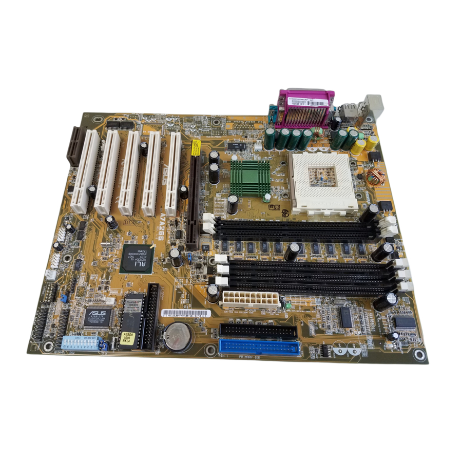
- Page 14 24.5cm (9.64in) PS/2 CPU_FAN USB1 USB2 COM1 JTPWR COM2 PWR_FAN MIC2 AUDIO_PANEL MODEM CLRTC A7A266 WOL_CON AFPANEL USB2 USB1 PANEL IDELED CHA_FAN...
- Page 18 Standby Powered Power A7A266 A7A266 Onboard LED...
- Page 19 1-10: Frequency Multiples A7A266 OFF ON A7A266 DIP Switch ™ ™ Jumper Mode Jumper Free (Default) A7A266 A7A266 Jumper Mode Setting OFF ON...
- Page 20 Enable Disable (Default) A7A266 A7A266 VID Selection A7A266 DDR DRAM SDRAM A7A266 DDR/SDR DIMM Selection...
- Page 21 100MHz 100MHz 120MHz 133MHz SDRAM 100MHz 133MHz 120MHz 133MHz A7A266 A7A266 CPU External Frequency Selection 90MHz 101MHz 126MHz SDRAM 90MHz 101MHz 126MHz...
- Page 22 A7A266 CPU Ratio CPU Ratio Disable Enable A7A266 CPU Ratio Setting 12.5x [OFF] [OFF] [ON] [ON] 12.0x [ON] [OFF] [ON] [ON] 11.5x [OFF] [ON] [ON] [ON] 11.0x [ON] [ON] [ON] [ON] 10.5x [OFF] [OFF] [OFF] [OFF] 10.0x [ON] [OFF] [OFF] [OFF] 9.5x...
- Page 23 5.0x 5.5x 6.0x 6.5x 7.0x 7.5x A7A266 8.0x 8.5x 9.0x 9.5x 10.0x 10.5x A7A266 CPU External Clock (BUS) Frequency Selection 11.0x 11.5x 12.0x >=12.5x...
- Page 25 • • • •...
- Page 26 104 Pins A7A266 80 Pins A7A266 184-Pin DDR DIMM Sockets 88 Pins A7A266 60 Pins 20 Pins A7A266 168-Pin SDR DIMM Sockets Lock 168-Pin DIMM Notch Key Definitions (3.3V) Voltage Key Position DRAM Key Position Reserved Unbuffered 5.0V 3.3V Buffered...
- Page 27 BLANK LEVER LOCK A7A266 NOTCH AMD™ Athlon A7A266 Socket A...
- Page 30 AGP Card without Retention Notch A7A266 TOP VIEW 20-pin bay 28-pin bay Rib (inside slot) A7A266 Accelerated Graphics Port (AGP PRO)
- Page 31 A7A266 A7A266 Audio Modem Riser (AMR) Slot ASUS MR-I Card...
- Page 32 ®...
- Page 33 PS/2 Mouse (6-pin Female) PS/2 Keyboard (6-pin Female)
- Page 34 USB 0 Universal Serial Bus (USB) 1 COM1 COM2 Serial Ports (9-pin Male) Parallel Port (25-pin Female)
- Page 35 Game/MIDI (15-pin Female) Line Out Line In 1/8" Stereo Audio Connectors NOTE: Orient the red markings on the floppy ribbon cable to PIN 1 A7A266 PIN 1 A7A266 Floppy Disk Drive Connector...
- Page 36 Primary Secondary S l a v e UltraDMA/100 UltraDMA/66 Master UltraDMA/100 UltraDMA/66 NOTE: Orient the red markings (usually zigzag) on the IDE ribbon cable to PIN 1. A7A266 PIN 1 A7A266 IDE Connectors...
- Page 37 A7A266 IDELED TIP: If the case-mounted LED does not light, try reversing the 2-pin plug. A7A266 IDE Activity LED A7A266 CHASSIS A7A266 Chassis Open Alarm Lead...
- Page 38 IMPORTANT: Requires an ATX power supply with at least 720mA +5 volt standby power. WOL_CON A7A266 +5 Volt Standby PME Ground A7A266 Wake-On-LAN Connector A7A266 Ground A7A266 Wake-On-Ring Connector...
- Page 39 CPU_FAN PWR_FAN +12V Rotation A7A266 CHA_FAN A7A266 12-Volt Cooling Fan Power JTPWR Power Supply Thermal Sensor A7A266 A7A266 Thermal Sensor Connector...
- Page 40 USB1 USB2 A7A266 A7A266 Front Panel USB Headers A7A266 A7A266 SMBus Connector...
- Page 41 AFPANEL Standard Infrared (SIR) Front View Back View A7A266 IR_CON IRTX (NC) A7A266 Front Panel Connectors IRRX AAPANEL MIC2 MICPWR AGND Line in_L Line out_L AGND2 AGND3 A7A266 Line in_R Line out_R A7A266 Audio Panel Connector...
- Page 42 CD1 (White) Left Audio Channel AUX (Black) Ground Right Audio Channel Modem-Out Ground Ground Modem-In A7A266 MODEM A7A266 Internal Audio Connectors MIC2 A7A266 A7A266 Internal Microphone Connector...
- Page 43 Ground Ground Power Supply On +5.0 Volts A7A266 Ground Ground +3.3 Volts -12.0Volts +3.3 Volts +3.3Volts A7A266 ATX Power Connector Requires an ATX power supply. Speaker Keylock Connector Power LED A7A266 Message LED Reset SW SMI Lead ATX Power Switch*...
- Page 50 ®...
- Page 52 MAIN ADVANCED POWER BOOT EXIT <F1> or <Alt + H> <Esc> or<Alt + X> (keypad arrow) (keypad arrows) - (minus key) + (plus key) or spacebar <Enter> <Home> or <PgUp> <End> or <PgDn> <F5> <F10>...
- Page 59 CR2032 3V Lithium Cell CMOS Power A7A266 CLRTC Short solder points to Clear CMOS A7A266 Clear RTC RAM...
- Page 60 ™...
- Page 74 ®...
- Page 78 ®...
- Page 80 • • • • • • • • • • • • • •...
- Page 91 AUTOEXEC.BAT BIOS Boot Bus Master IDE Byte...
- Page 92 Cache CMOS Cylinder Device Driver DIMM...
- Page 93 DRAM MIDI MPEG NTSC...
- Page 94 PCI Bus PCMCIA Peripherals POST SCSI UltraDMA/33...