Sign In
Upload
Manuals
Brands
York Manuals
Heat Pump
YLUA0248 Series
York YLUA0248 Series Manuals
Manuals and User Guides for York YLUA0248 Series. We have
1
York YLUA0248 Series manual available for free PDF download: Installation Operation & Maintenance
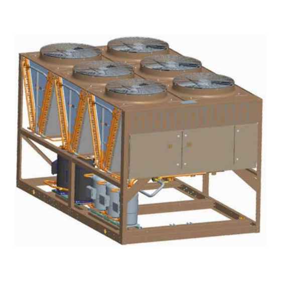
York YLUA0248 Series Installation Operation & Maintenance (158 pages)
AIR-COOLED SCROLL CONDENSING UNITS
Brand:
York
| Category:
Heat Pump
| Size: 8.54 MB
Table of Contents
Table of Contents
5
Section 1 - General Equipment Information and Safety
11
Compressors
11
Condenser
11
Introduction
11
Refrigerant Circuit
11
Warranty
11
About this Manual
12
Safety and Quality
12
Misuse of Equipment
13
FIGURE 1 - Compressors
15
Microcomputer Control Center
16
Refrigerant Circuit
16
Communications
17
High Ambient Kit
17
Power Panel
17
Accessories and Options
18
Unit Components
20
Section 2 - Product Description
15
General System Description
15
Introduction
15
FIGURE 2 - Unit Components Front
20
FIGURE 3 - Power Panel Components
21
FIGURE 4 - Power Panel / Control Components
22
FIGURE 5 - Refrigerant Flow Diagram
28
Process and Instrumentation Diagram
29
Product Identification Number (Pin)
23
Refrigerant Flow Diagram
28
FIGURE 6 - Process and Instrumentation Diagram
29
FIGURE 7 - Unit Rigging
31
Section 3 - Handling and Storage
31
Delivery and Storage
31
Inspection
31
Unit Rigging
31
Section 4 - Installation
33
Handling
33
Installation Checklist
33
Location and Clearances
33
Compressor Mounting
34
Duct Work Connection
34
Pipework Arrangement
34
Spring Isolators (Optional)
34
Wiring
34
Compressor Heaters
35
Electrical Wiring
35
High Pressure Cutout
35
Relief Valves
35
Compressor Heaters
37
Refrigerant Piping
37
Refrigerant Piping Reference
37
YCRL Line Sizing Notes
37
TABLE 2 - Refrigerant Piping Charges
38
TABLE 3 - Miscellaneous Liquid Line Pressure Drops
38
TABLE 5 - Refrigerant Line Pressure Drops (English)
41
FIGURE 8 - Single-Point Supply Connection - Terminal Block, Non-Fused Disconnect Switch
42
FIGURE 9 - Discharge Air Sensor Field Wiring
42
Control Wiring
43
TABLE 1 - Fitting Equivalent Lengths
38
TABLE 4 - Refrigerant Line Connections
39
Filter Driers/ Sight Glasses/ Txvs
40
Oil Traps
40
Refrigerant Charge
40
Refrigerant Line Sizing
40
Refrigerant Piping Notes
41
FIGURE 10 - Control Wiring
43
Section 5 - Technical Data
45
Operational Limitations (English)
45
TABLE 6 - Voltage Limitations
45
TABLE 7 - Physical Data (English)
46
Electrical Data
47
Physical Data (English)
46
TABLE 9 - Voltage Range
47
TABLE 8 - Micro Panel Power Supply
47
TABLE 10 - Unit Electrical Data
48
TABLE 11 - Lug Sizing
49
FIGURE 11 - Elementary Wiring Diagram
54
Wiring Diagrams
54
FIGURE 12 - Elementary Wiring Diagram
56
FIGURE 13 - Elementary Wiring Diagram
58
FIGURE 14 - Elementary Wiring Diagram
60
FIGURE 15 - Elementary Wiring Diagram
62
FIGURE 16 - Power Options Connection Diagram
64
FIGURE 17 - Power Panel
66
FIGURE 18 - Single Point & Dual Point Wiring
68
FIGURE 19 - Wiring
70
FIGURE 20 - Micro Panel Connections
72
FIGURE 21 - Elementary Diagram
74
FIGURE 22 - Elementary Diagram
76
FIGURE 23 - Unit Clearances - All Models
81
Weight Distribution and Isolator Mounting Positions
82
Isolator Information
83
Dimensions (English)
78
Clearances
81
Section 6 - Commissioning
89
Commissioning
89
Preparation - Power off
89
Preparation - Power on
90
Section 7 - Unit Controls
95
Introduction
95
Microprocessor Board
95
Battery Back-Up
96
Display
96
Keypad
96
Single System Select and Programming Number of Compressors
96
Transformer
96
Unit Switch
96
Status Key
97
TABLE 12 - Status Key Messages Quick Reference List
101
TABLE 13 - Operation Data
105
Entry Keys
110
Setpoints Keys
111
Display/Print Keys
102
TABLE 15 - Program Key Limits and Defaults
116
TABLE 14 - Cooling Setpoints Programmable Limits and Defaults
116
FIGURE 24 - Setpoints Quick Reference List
117
Unit Keys
118
FIGURE 25 - Unit Keys Programming Quick Reference List
123
Section 8 - Unit Operation
125
Capacity Control
125
Discharge Air Temperature Control
125
Discharge Pressure Limit Controls
125
Suction Pressure Limit Controls
125
FIGURE 26 - Discharge Air Temperature Control
126
TABLE 16 - Discharge Air Temperature Control for 5 and 6 Compressors (7 and 8 Steps)
126
TABLE 17 - Discharge Air Temperature Control for 4 Compressors (6 Steps)
126
FIGURE 27 - Suction Pressure Control
127
Anti-Coincidence Timer
128
Anti-Recycle Timer
128
Compressor Lead/Lag
128
Evaporator Blower Control
128
Pumpdown Control
128
System Lead/Lag
128
Suction Pressure Control
127
FIGURE 28 - YLUA0248 - YLUA0298 Fan Location (Typical)
129
TABLE 20 - YLUA0248 - YLUA0298 Low Ambient Condenser Fan Control - Discharge Pressure Control
130
FIGURE 29 - YLUA0308 - YLUA0408 Fan Location
131
FIGURE 30 - YLUA0468 - YLUA0498 Fan Location
132
TABLE 23 - Compressor Operation - Load Limiting
133
BAS/EMS Discharge Air Temperature Reset Using a Voltage or Current Signal
134
TABLE 22 - YLUA0468 - YLUA0498 Condenser Fan Control
132
Alarm Status
133
Compressor Run Status
133
Load Limiting
133
TABLE 19 - YLUA0248 - YLUA0298 Condenser Fan Control Using Discharge Pressure Only
129
TABLE 18 - YLUA0248 - YLUA0298 Condenser Fan Control Using Outdoor Ambient Temperature and Discharge Pressure
129
TABLE 21 - YLUA0308 - YLUA0408 Condenser Fan Control
131
Condenser Fan Control
132
Section 9 - Service and Troubleshooting
135
Clearing History Buffers
135
Service Mode
135
Service Mode - Outputs
135
Service Mode - Analog and Digital Inputs
136
Service Mode - Condensing Unit Configuration
136
Control Inputs/Outputs
137
TABLE 25 - I/O Digital Outputs
137
TABLE 28 - Outdoor Air Sensor Temperature/Voltage/ Correlation
139
TABLE 29 - Discharge Air Temp. Sensor Temperature/Voltage/Resistance Correlation
140
TABLE 30 - Pressure Transducers
141
FIGURE 32 - I/O Board Relay Contact Architecture
142
FIGURE 33 - Printer to Microboard Electrical Connections
143
Troubleshooting
144
TABLE 26 - I/O Analog Inputs
137
TABLE 27 - I/O Analog Outputs
137
Optional Printer Installation
143
TABLE 24 - I/O Digital Inputs
137
FIGURE 31 - Microboard Layout
138
Checking Inputs and Outputs
139
TABLE 31 - Troubleshooting
144
Section 10 - Maintenance
147
Compressors
147
Condenser Coils
147
Condenser Fan Motors
147
Important
147
On-Board Battery Back-Up
147
Operating Parameters
147
Overall Unit Inspection
147
ISN Control
148
TABLE 33 - ISN Transmitted Data
148
TABLE 32 - ISN Received Data
148
TABLE 34 - ISN Operational and Fault Codes
150
Bacnet and Modbus Data Communication
151
TABLE 35 - Minimum, Maximum and Default Values
152
TABLE 36 - Real Time Error Numbers
152
TABLE 37 - Serial Communication Analog Value Data
153
TABLE 38 - Serial Communication Binary Value Data
153
TABLE 39 - Serial Communication Analog Input Data
153
TABLE 40 - Serial Communication Binary Input Data
155
Advertisement
Advertisement
Related Products
York YLUA0298 Series
York YLUA0308 Series
York YLUA0408 Series
York YLUA0468 Series YLUA0498 Series
York YLUA0078
York YLUA0158
York YLHA 80
York YLPA
York YLCA Series
York YLCA PLUS 9
York Categories
Air Conditioner
Heat Pump
Chiller
Furnace
Air Handlers
More York Manuals
Login
Sign In
OR
Sign in with Facebook
Sign in with Google
Upload manual
Upload from disk
Upload from URL