Sign In
Upload
Manuals
Brands
York Manuals
Chiller
YLAA0092HE
York YLAA0092HE Manuals
Manuals and User Guides for York YLAA0092HE. We have
1
York YLAA0092HE manual available for free PDF download: Installation Operation & Maintenance
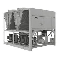
York YLAA0092HE Installation Operation & Maintenance (208 pages)
Air-Cooled Scroll Chillers with Brazed Plate Heat Exchanger Style B (60 Hz) 4 to 12 Fan 40 ton to 230 ton 140 kW to 800 kW
Brand:
York
| Category:
Chiller
| Size: 18.59 MB
Table of Contents
Table of Contents
5
Section 1: General Chiller Information and Safety
11
Introduction
11
Warranty
11
Handling
11
Safety and Quality
12
About this Manual
12
Misuse of Equipment
12
Section 2: Product Description
15
Introduction
15
General System Description
15
Table 1: Canadian Registration Numbers
16
Communications
17
Building Automation System Interface
18
Power Panel
18
Accessories and Options
18
Figure 1: Unit Components, Front View
21
Figure 2: Unit Components, Side View
22
Figure 3: Power Panel Components
23
Figure 4: Power Panel and Control Components
24
Table 2: Complete Pin Number Description
25
Figure 5: Process and Instrumentation Diagram
31
Section 3: Handling and Storage
33
Figure 6: Rigging and Lifting Label
33
Delivery and Storage
34
Inspection
34
Moving the Chiller
34
Figure 7: Unit Rigging/Lifting
35
Lifting Weights
36
Lifting Using Lugs
36
Lifting Using Shackles
36
Figure 8: Lifting Lugs
36
Section 4: Installation
37
Installation Checklist
37
Location and Clearances
37
Spring Isolators: Optional
38
Compressor Mounting
38
Chilled Liquid Piping
38
Pipework Arrangement
39
Wiring
39
Figure 9: Chilled Liquid System
39
Relief Valves
40
High Pressure Cutout
40
Single-Point Supply Connection - Terminal Block, Non-Fused Disconnect Switch or Circuit Breaker
41
Figure 10: Single-Point Supply Connection - Terminal Block, Non-Fused Disconnect Switch or Circuit Breaker
41
Figure 11: Control Wiring Inputs
42
Table 3: Chemical Specification of Water
43
Figure 12: Thermal Dispersion Flow Switch
44
Figure 13: Wiring of Thermal Dispersion Flow Switch
44
Figure 14: Control Wiring Outputs
46
Section 5: Technical Data
47
Table 4: Temperatures and Flows
47
Table 5: Ethylene and Propylene Glycol Correction Factors
49
Physical Data YLAA0041 to YLAA0230, 60 Hz
50
Table 6: Physical Data and Nominal Data
50
Electrical Data
57
Compressor Heaters
57
Table 7: Micropanel Power Supply
57
Table 8: Voltage Range
57
Table 9: Pump Electrical Data 60 Hz
58
Table 10: Transformer Load
58
Table 11: Electrical Data Without Pumps, R-410A
59
Table 12: Electrical Data Without Pumps R-454B
65
Table 13: Wiring Lugs
70
Electrical Notes
73
Figure 15: Elementary Wiring Diagram
78
Figure 16: Elementary Wiring Diagram
79
Figure 17: Fan Wiring, Standard Air Flow
82
Figure 18: Fan Wiring, High Air Flow
84
Figure 19: Single and Dual Point Wiring Options
86
Figure 20: Pump Wiring
88
Figure 21: EEV Controller Elementary Diagram
90
Figure 22: Compressor Wiring
92
Figure 23: Power Options Connection Diagram
94
Figure 24: Power Panel
96
Figure 25: Micro Panel Connections
99
Figure 26: Four Fan Units Dimensions - YLAA0041HE, YLAA0048HE, YLAA0058HE, YLAA0065HE
100
Figure 27: Four Fan Units Dimensions - YLAA0070SE, YLAA0080SE, YLAA0089SE
101
Figure 28: Four Fan Units Dimensions - YLAA0070ZJ
102
Figure 29: Five Fan Units Dimensions - YLAA0100SE
103
Figure 30: Five Fan Units Dimensions - YLAA0100ZJ
104
Figure 31: Six Fan Units Dimensions - YLAA0092HE, YLAA0101HE, YLAA0115SE, YLAA0120SE
105
Figure 32: Eight Fan Units Dimensions - YLAA0125HE, YLAA0136SE, YLAA0139HE, YLAA0142HE
106
Figure 33: Eight Fan Units Dimensions - YLAA0155ZJ
107
Figure 34: Ten Fan Units Dimensions - YLAA0170SE, YLAA0156HE, YLAA0175HE
108
Figure 35: Twelve Fan Units Dimensions - YLAA200HE, YLAA0230HE
109
Weight Distribution and Isolator Mounting Positions
110
Figure 36: Sample Printout Supplied in the Isolator Package and in the Chiller Panel Literature Packet
110
Clearances
111
Figure 37: Unit Clearances - All Models
111
Isolator Locations
112
Isolator Information
115
Section 6: Commissioning
121
Preparation, with Power off
121
Figure 38: EEV IB-G Interface Board
123
Commissioning the Pump VFD
124
Preparation, with Power on
124
Figure 39: Drive Display
126
Table 14: Drive Programming Parameters
126
Figure 40: Circuit Breaker Panel
127
Determining Proper Oil Levels
128
Figure 41: Tandem Set
128
Figure 42: Trio Set
128
Section 7: Unit Controls
133
Introduction
133
IPU II and I/O Boards
133
Transformer
134
Display
134
Keypad
134
Unit Switch
134
Battery Backup
134
Programming the Number of Compressors
134
Status Key
135
Table 15: YLAA Fault and Inhibit Codes
142
Table 16: Legend
142
Figure 43: Status Key Messages Quick Reference List
143
Display/Print Keys
144
Figure 44: Operation Data
147
Entry Keys
152
Setpoints Keys
153
Schedule/Advance Day Key
154
Table 17: Cooling Setpoint, Programmable Limits, and Defaults
155
Program Key
156
Table 18: Program Key Limits and Default
158
Figure 45: Setpoints Quick Reference List
159
Table 19: Program Key Limits and Default
160
Unit Keys
162
Figure 46: Unit Keys Options Programming Quick Reference List
169
Bacnet, Modbus, N2, and Yorktalk 2 Communications
170
Figure 47: Micro Panel Connections
171
Table 20: Minimum, Maximum and Default Values
171
Table 21: Values Required for BAS Communication
172
Table 22: Real Time Error Numbers
173
Section 8: Unit Operation
175
Capacity Control
175
Suction Pressure Limit Controls
176
Discharge Pressure Limit Controls
176
Leaving Chilled Liquid Control
176
Figure 48: Leaving Water Temperature Control Example
176
Leaving Chilled Liquid Control Override to Reduce Cycling
177
Figure 49: Setpoint Adjust
177
Table 23: Sample Compressor Staging for Return Water Control
177
Leaving Chilled Liquid System Lead/Lag and Compressor Sequencing
178
Return Chilled Liquid System Lead/Lag and Compressor Sequencing
178
Anti-Recycle Timer
178
Anti-Coincidence Timer
178
Evaporator Pump Control and YORK Hydro Kit Pump Control
178
Evaporator Heater Control
179
Pumpdown Control
179
Standard Condenser Fan Control
179
VSD Fan
179
Changing the Switch Point of the Thermal Dispersion Flow Switch
179
Figure 50: Condenser Fan Locations
180
Table 24: YLAA Standard Condenser Fan Control Using Discharge Pressure Only (2, 3, or 4 Fans Per System)
181
Table 25: YLAA Standard Condenser Fan Control Using Discharge Pressure Only (5 or 6 Fans Per System)
182
Load Limiting
183
Compressor Run Status
183
Alarm Status
183
Table 26: Compressor Operation Load Limiting
183
Remote BAS/EMS Temperature Reset Using a Voltage or Current Signal
184
Section 9: Service and Troubleshooting
185
Clearing History Buffers
185
Resetting System Lockout Faults
185
Service Mode
185
Service Mode, Outputs
185
Service Mode, Chiller Configuration
186
Service Mode, Analog and Digital Inputs
186
Control Inputs/Outputs
187
Table 27: I/O Digital Inputs
187
Table 28: I/O Digital Outputs
187
Table 29: I/O Analog Inputs
187
Table 30: I/O Analog Outputs
187
Figure 51: Microboard Layout
188
Checking Inputs and Outputs
189
Table 31: Outdoor Air Sensor Temperature/Voltage/Correlation
189
Table 32: Entering/Leaving Chilled Liquid Temp. Sensor, Temperature/Voltage Correlation
190
Table 33: Pressure Transducers
191
Figure 52: I/O Board Relay Contact Architecture
192
Table 34: Data Logging to Flash
193
Optional Printer Installation
195
Figure 53: Printer to Microboard Electrical Connections
196
Troubleshooting
197
Table 35: Troubleshooting
197
Section 10: Maintenance
199
Compressors
199
Condenser Fan Motors
199
Condenser Round Tube Coils
199
Condenser MCHX
199
Microchannel Coil Cleaning
199
Operating Parameters
202
On-Board Battery Backup
202
Thermal Dispersion Flow Switch
202
Brazed Plate Heat Exchanger (Evaporator) Heater
202
Overall Unit Inspection
202
Table 36: Cleaning Materials
202
Table 37: Temperature Conversion Chart
203
Table 38: R-410A Pressure Temperature Chart
204
Table 39: R-454B Pressure Temperature Chart
205
Temperature
206
Table 40: SI-Metric Conversion
206
Advertisement
Advertisement
Related Products
York YLAA0092
York YLAA0058
York YLAA0065
York YLAA0080
York YLAA0070
York YLAA0089
York YLAA0070SE
York YLAA0089SE
York YLAA0070ZJ
York YLAA0048HE
York Categories
Air Conditioner
Heat Pump
Chiller
Furnace
Air Handlers
More York Manuals
Login
Sign In
OR
Sign in with Facebook
Sign in with Google
Upload manual
Upload from disk
Upload from URL