Sign In
Upload
Manuals
Brands
York Manuals
Chiller
YK LB LB G4 THRU YK SE SC J4
York YK LB LB G4 THRU YK SE SC J4 Manuals
Manuals and User Guides for York YK LB LB G4 THRU YK SE SC J4. We have
1
York YK LB LB G4 THRU YK SE SC J4 manual available for free PDF download: Operating & Maintenance Manual
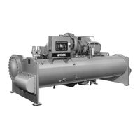
York YK LB LB G4 THRU YK SE SC J4 Operating & Maintenance Manual (61 pages)
CENTRIFUGAL LIQUID CHILLERS WITH MICROCOMPUTER CONTROL CENTER
Brand:
York
| Category:
Chiller
| Size: 2.13 MB
Table of Contents
Table of Contents
2
Nomenclature
3
Description of System and Fundamentals of Operation
4
Capacity Control
5
Compressor Prerotation Vanes View
5
Refrigerant Flow-Thru Chiller View
5
Microcomputer Control Center and Keypad
6
SECTION 2 – Microcomputer Control Center
6
Control Center Description
8
Operation
8
Displaying System Parameters
8
To Display Chilled Liquid Temperatures
9
To Display Refrigerant Pressure
9
To Display Oil Pressure
9
To Display Options
9
System Setpoints
10
Chilled Liquid Temp
10
% Current Limit
10
Pull down Demand
10
Daily Schedule
11
Holiday
11
Remote/Reset Temp Range
11
Low/High Line Voltage Trip/Reset Values
11
Displaying System Setpoints
12
To Display Chilled Liquid Temp Setpoint
12
To Display % Current Limit Setpoint
12
To Display Daily Schedule Setpoints
12
To Display Holiday Setpoint
13
To Display Remote Reset Temp Range Setpoint
13
To Display Data Logger Setpoints
13
To Display Undervoltage Setpoints
13
Programming the Microcomputer Control Center
14
Programming System Setpoints
14
To Enter Chilled Liquid Temp Setpoint
15
To Enter % Current Limit Setpoint
15
To Enter Pull down Demand Setpoint
16
To Enter Clock Setpoint
16
To Enter Daily Schedule Setpoint
17
To Enter Holiday Setpoint
18
To Enter Remote/Reset Temp Range Setpoint
18
Service Keys
19
Pre-Rotation Vanes Keys
19
Manual Oil Pump
20
Display Data
20
Manual Vane Operatoin Allowed Message
20
Manual Level Control Allowed Message
20
Operating Modes
21
Display Messages
22
Compressor Switch
22
To Reset Control Center
22
System Run - Current Limit in Effect Message
22
System Run - Vanes Opening Message
23
System Run - Vanes Closing Message
23
System Run - Vanes Holding Message
23
System Run - Auto Level Control Message
23
System Shutdown Messages
24
Warning: Cond or Evap Transducer Error Message
24
Syster Run - Leaving Temp Control Message
24
System Shutdown - Press Status Message
24
Mon XX:XX am - Power Failure Message
25
System Run - Leaving Termp Control Message
25
Remote Stop Message
25
Anti-Recycle, 00 Min Left Message
25
Mon XX:XX am - Evap Trans or Probe Error Message
26
Mon XX:XX am - Motor Controller - Ext. Reset Message
26
Mon XX:XX am - Power Fault - Autostart Message
26
Mon XX:XX am - Faulty Cond Pressure XDCR Message
26
System Ready to Start - Press Status Message
27
Start Sequence Initiated Message
27
System Coastdown Message
27
Mon XX:XX am - MTR Phase Current Unbalance Message
27
Mon XX:XX am - High Line Voltage Message
28
Mon XX:XX am - Low Oil Temp Diff - Autostart Message
28
Day - Time - Oil Pressure XDCR Error Message
28
Mon XX:XX am - Prox Sensor Safety Shutdown Message
28
Mon XX:XX am - High Speed Drain Temp
29
Mon XX:XX am - Open Drain Temp Thermocouple
29
Mon XX:XX am - DC Undervoltage
29
Replace RTC. U16 - Reprogram Setpoints
29
Start-Up Procedure
30
Pre-Starting
30
Checking the Oil Level in the Oil Reservoir
30
SECTION 3 – System Operating Procedures
30
Chiller Operation
31
Chiller Starting Sequence and Shutdown Sequence
32
Condenser Water Temperature Control
32
Checking Operation
33
Operating Log Sheet
33
Operating Inspections
34
Need for Maintenance or Service
35
Normal and Safety System Shutdown
35
Safety Shutdowns/Cycling Shutdowns
35
Stopping the System
35
Prolonged Shutdown
36
Start-Up after Prolonged Shutdown
36
Product View and Parts Identification
37
SECTION 4 – System Component Description
37
Compressor
38
Compressor Lubrication System
38
Oil Pump
38
Schematic Drawing - (YK) Compressor Lubrication System
39
Oil Heater
40
Motor Driveline
40
Heat Exchangers
40
Refrigerant Flow Control
40
Microcomputer Control Center
41
Solid State Starter
41
Variable Speed Drive
41
Actual Level = XXX%; Level Setp = XXX% Message
41
Oil Return System
42
Changing the Dehydrator
42
SECTION 5 – Operational Maintenance
42
The Oil Charge
43
Charging Oil Reservoir with Oil View
43
Troubleshooting
44
Causes of Normal and Safety System Shutdowns
44
Operating Analysis Chart
47
Evacuation and Dehydration of Unit
49
Leak Testing During Operation
49
Conducting R-22 Pressure Test
49
SECTION 7 – Maintenance
49
Vacuum Testing
50
System Pressures Table
50
Vacuum Dehydration
51
Saturatoin Curve
51
Refrigerant Charging
52
Checking the Refrigerant Charge During Unit Shutdown
52
Handling Refrigerant for Dismantling and Repairs
53
Megging the Motor
53
Minimum Insulation Resistance Vs. Temperature
54
Condensers and Coolers
55
Chemical Water Treatment
55
Cleaning Cooler and Condenser Tubes
55
Tube Cleaning Procedures
55
Testing for Cooler and Condenser Tube Leaks
56
Compressor Maintenance
57
SECTION 8 – Preventive Maintenance
58
Advertisement
Advertisement
Related Products
York LB360
York LB480
York LB600
York LB 180
York LB 240
York LEU360
York LEU600
York LF8S Series
York LVD 503
York LHA-90
York Categories
Air Conditioner
Heat Pump
Chiller
Furnace
Air Handlers
More York Manuals
Login
Sign In
OR
Sign in with Facebook
Sign in with Google
Upload manual
Upload from disk
Upload from URL