Sign In
Upload
Manuals
Brands
York Manuals
Chiller
YCIV Series
York YCIV Series Air-Cooled Screw Chiller Manuals
Manuals and User Guides for York YCIV Series Air-Cooled Screw Chiller. We have
1
York YCIV Series Air-Cooled Screw Chiller manual available for free PDF download: Installation Operation & Maintenance
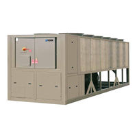
York YCIV Series Installation Operation & Maintenance (326 pages)
AIR-COOLED SCREW LIQUID CHILLERS E/V HIGH EFFICIENCY AND S/P STANDARD EFFICIENCY
Brand:
York
| Category:
Chiller
| Size: 12 MB
Table of Contents
Table of Contents
5
Section 1 - General Chiller Information and Safety
11
Introduction
11
Warranty
11
Safety
11
About this Manual
12
Misuse of Equipment
12
Section 2 - Product Description
15
Introduction
15
FIGURE 2 - Compressor
16
FIGURE 1 - Chiller Control System
16
FIGURE 4 - PWM Voltage Waveform
21
FIGURE 3 - PWM Current Waveform
21
Accessories and Options
22
Complete Pin Number Description
25
Section 3 - Rigging, Handling and Storage
29
Lifting Weights
29
Delivery and Storage
29
Inspection
29
Moving the Chiller
30
Unit Removal from Shipping Container
30
Lifting Using Lugs
30
Lifting Using Shackles
30
Section 4 - Installation
33
Indoor Installations
33
Location Clearances
33
Location Requirements
33
Outdoor Installations
33
Chilled Liquid Piping
34
Shipping Braces
34
Vibration Isolators
34
Water Treatment
35
Connection Types and Sizes
36
Cooler Connections
36
FIGURE 7 - Flange Attachment
36
FIGURE 6 - Grooved Nozzle
36
FIGURE 5 - Pipework Arrangement
36
Pipework Arrangement
36
Refrigerant Relief Valve Piping
36
Ductwork Connection
37
Electrical Connection
37
115 Vac Control Supply Transformer
38
Control Panel Wiring
38
Power Supply Wiring
38
Power Wiring
38
System Inputs
39
Volts Free Contacts
39
Section 5 - Commissioning
41
Preparation
41
Preparation - General
41
First Time Start-Up
42
Section 6 - Technical Data
51
Glycol Correction Factors
55
FIGURE 9 - Two Compressor Wiring Diagram with Terminal Block
66
FIGURE 11 - Three Compressor Wiring Diagram with Terminal Block - Single Point
67
FIGURE 10 - Three Compressor Wiring Diagram with Circuit Breaker - Single Point
67
TABLE 1 - Typical Compressor Starting Current (First Four Seconds of Start-Up)
80
TABLE 2 - Voltage Utilization Range
80
Electrical Wiring Diagrams - 2 Compressor Models
82
FIGURE 8 - Two Compressor Wiring Diagram with Circuit Breaker
66
Electrical Notes
80
FIGURE 12 - Elementary Control Wiring Diagram 2 Compressor Models
82
FIGURE 17 - Control Elementary Diagram - YCIV0257-0397 3 Compressor Models
96
FIGURE 18 - Power Elementary Diagram - YCIV0257-0397 3 Compressor Models
100
FIGURE 19 - Control Wiring Connection Diagram - YCIV0257-0397 3 Compressor Models
102
FIGURE 20 - Power Wiring Connection Diagram - YCIV1050-1500 3 Compressor Models
106
FIGURE 21 - Power Elementary Diagram - YCIV0257-0397 3 Compressor Models
108
FIGURE 22 - Refrigerant Flow Diagram
161
FIGURE 23 - Process and Instrumentation Diagram
162
Process and Instrumentation Diagram
162
Component Locations
163
Dimensions - 2 and 3 Compressor si
112
Technical Data - Clearances
132
Isolator Information for Units Shipped on or after June 15, 2008
133
Isolator Information for Units Shipped before June 15, 2008
156
Refrigerant Flow Diagram
161
FIGURE 13 - Elementary Power Wiring Diagram - YCIV0157-0267 2 Compressor Models
84
FIGURE 14 - Power Wiring Connection Diagram - YCIV0157-0267 2 Compressor Models
86
FIGURE 15 - Control Wiring Connection Diagram - YCIV0157-0267 2 Compressor Models
88
FIGURE 16 - Power Elementary Wiring Diagram - YCIV0157-0267 2 Compressor Models
91
Electrical Wiring Diagrams - 3 Compressor Models
96
FIGURE 24 - Component Locations
163
FIGURE 25 - Control and VSD Cabinet Components
164
FIGURE 26 - Chiller Control Board, Relay Boards, Microgateway, and Optional Circuit Breaker
165
FIGURE 27 - Chiller Control Board, Relay Boards, and Microgateway, 2 Compressor
166
FIGURE 28 - Chiller Control Board, Relay Boards, and Microgateway, 3 Compressor
167
FIGURE 29 - VSD Logic Board
168
FIGURE 30 - VSD Logic Board (Original - Obsolete), P/N 031-02477-000
169
FIGURE 31 - VSD Logic Board (New), P/N 031-02507-XXX
170
FIGURE 32 - Power Components, 2 Compressor
171
FIGURE 33 - Power Components, 3 Compressor
172
FIGURE 34 - Fan Contactors and 3T Transformer, 2 Compressor
173
FIGURE 35 - Fan Contactors, 3 Compressor
174
FIGURE 36 - VSD Components
175
FIGURE 37 - VSD Components, 2 Compressor
176
FIGURE 38 - VSD Components, 3 Compressor
177
FIGURE 39 - VSD Components, 2 Compressor
178
FIGURE 40 - VSD Components, 3 Compressor
179
FIGURE 41 - Inverter Power Components, 2 Compressor
180
FIGURE 42 - Inverter Power Components, 3 Compressor
181
FIGURE 44 - Glycol Pump and Fill Tube Locations
184
FIGURE 45 - Glycol Piping and Fill Tube Location
185
FIGURE 46 - Compressor Components
186
Chiller Electronic Components
187
FIGURE 47 - New Board P/N 031-02507-000
192
FIGURE 48 - Obsolete Board P/N 031-02477-000
192
Chiller Configuration Jumpers
195
TABLE 3 - Compressors and the Appropriate Jumper Positions
195
Maximum VSD Frequency/Model Designator
196
VSD Logic to Chiller Microprocessor Board RS-485 Communication Configuration Jumpers
196
Compressor Components
186
FIGURE 43 - Inverter Power Components
182
Glycol System Components
184
TABLE 4 - VSD Logic Board Address Jumper
196
TABLE 5 - Maximum Frequency / Model Designator Jumper
196
Section 7 - Operation
197
Operating Controls
197
Basic Operating Sequence
198
FIGURE 49 - Chiller Control (Cooling) Range
199
Number of Compressors to Start
199
FIGURE 50 - Number of Compressors to Start
200
FIGURE 51 - Minimum VSD Start Frequency
200
FIGURE 52 - Minimum VSD Run Frequency
201
Optional High IPLV Capacity Control
203
TABLE 6 - Fuzzy Logic Loading/Unloading Vs. Error
203
TABLE 7 - Fuzzy Logic Loading/Unloading Vs. Error
205
Load Limiting Control
206
Minimum VSD Compressor Start / Run Frequency
200
Acceleration / Deceleration Rate When Starting / Stopping Compressors
201
Standard IPLV Capacity Control
201
TABLE 8 - Current Limit Load Limiting/Unloading
206
TABLE 10 - Suction Pressure Load Limiting/Unloading
207
TABLE 9 - Discharge Pressure Load Limiting/Unloading
207
FIGURE 53 - Flash Tank Drain and Feed Valve Controller
208
TABLE 12 - VSD Baseplate Temperature Load Limiting/Unloading
208
FIGURE 54 - LED Locations
210
FIGURE 55 - Power and Comms Led's
210
FIGURE 56 - Power, Comms and System Open/Close Led's
210
Economizer Control
211
Condenser Fan Control
212
FIGURE 57 - Condenser Fan Locations
212
TABLE 13 - Fan Stages and Corresponding Outputs
212
FIGURE 58 - Standard IPLV Fan Control
213
FIGURE 59 - High IPLV Fan Control
213
Remote Temperature Reset Control
214
Remote Current Limit Reset Control
215
Sound Limit Control
217
VSD Temperature Control, Operation of the Coolant Pump, and VSD Cabinet Cooling Fans
213
TABLE 11 - VSD Internal Ambient Load Limiting/Unloading
207
Flash Tank Drain and Feed Valve Controller
208
Section 8 - Micropanel
219
VSD Operation and Controls
219
TABLE 14 - VSD Operating Display Parameters
223
FIGURE 60 - Microboard 331-03478-XXX
230
Program Update
231
Data Logging
232
VSD Safeties (Faults)
223
Microboard (331-03478-XXX)
229
Unit Warnings
229
TABLE 15 - Flash Card Update Error XXXXX
232
TABLE 17 - Low Differential Oil Pressure Cutout
237
TABLE 18 - Start Inhibit Sensor Thresholds
239
TABLE 19 - Sensor Min/Max Outputs
247
VSD Data Key
248
Operating Hours / Start Counter Key
250
History Key
251
Setpoints Key
258
TABLE 20 - Setpoint Limits
259
Program Key
260
TABLE 21 - Programmable Operating Parameters
262
Options Key
263
Date / Time and Schedule Keys
266
Manual Override Key
270
Print Key
271
TABLE 22 - Printout Types
271
Service Key
274
System Switches Key
280
Serial Number Programming
281
Enabling Optimized High IPLV Mode
282
TABLE 23 - Unit Setup Programmable Values
283
Unit Setup Mode
283
Default Programmable Values
284
Serial Port Connections
284
Analog Input Connections
285
TABLE 24 - Serial Port Connections
285
TABLE 25 - Analog Input Connections
285
Digital Intput Connections
287
TABLE 26 - Digital Input Connections
287
Analog Output Connections
288
TABLE 27 - Analog Output Connections
288
Digital Output Connections
289
TABLE 28 - Digital Output Connections
289
BACNET, MODBUS and YORKTALK 2 Communications
291
TABLE 16 - Data Logging
232
Status Key
240
Unit Data Key
243
System Data Keys 1 through 4
245
Unit Safeties
233
System Safeties (Faults)
235
FIGURE 61 - Control Board Connections
292
TABLE 29 - Minimum, Maximum and Default Values
292
TABLE 30 - Values Required for BAS Communication
293
TABLE 31 - Real Time Error Numbers
293
TABLE 32 - Bacnet and Modbus Communications Data Map
295
TABLE 33 - Yorktalk 2 Communications Data Map
301
Section 9 - Maintenance
305
Evacuating a System
305
General Requirements
305
R-134A Conversion Tables
306
TABLE 34 - R-134A Pressure to Saturated Temperature Conversion
306
Maintenance Requirements for YCIV Chillers
307
Troubleshooting Guide
308
Limited Warranty
310
Chilled Liquid and Suction Temperature Sensor Input Voltage
311
TABLE 35 - Temperature Input Voltage Sensor (Measured Signal to Shield at the Sensor)
311
TABLE 36 - Outside Air Temperature Sensor Input Voltage (Measured Signal to Shield at the Sensor)
312
TABLE 37 - Pressure Transducer Output Voltage (Measured Signal to Return at the Transducer)
313
TABLE 38 - Motor Temperature Sensor Resistance (Check at the Motor)
314
TABLE 39 - Compressor Motor Overload Settings and Max. VSD Frequency
315
FIGURE 62 - Print Cable - Chiller to Serial Printer
318
Operating Log Sheet
320
Recommended Spare Parts
324
Printer Wiring
318
Advertisement
Advertisement
Related Products
York Latitude YCIV0267P
York Latitude YCIV0287P
York Latitude YCIV0207V
York Latitude YCIV0327V
York Latitude YCIV1180P
York Latitude YCIV1340P
York Latitude YCIV0207S
York Latitude YCIV0930E
York YCIV0247S/P
York YCIV0227E/V
York Categories
Air Conditioner
Heat Pump
Chiller
Furnace
Air Handlers
More York Manuals
Login
Sign In
OR
Sign in with Facebook
Sign in with Google
Upload manual
Upload from disk
Upload from URL