Sign In
Upload
Manuals
Brands
York Manuals
Chiller
YCAS0685EB Series
User Manuals: York YCAS0685EB Series Water Chiller
Manuals and User Guides for York YCAS0685EB Series Water Chiller. We have
1
York YCAS0685EB Series Water Chiller manual available for free PDF download: Installation Operation & Maintenance
York YCAS0685EB Series Installation Operation & Maintenance (216 pages)
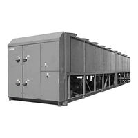
AIR-COOLED SCREW LIQUID CHILLERS
Brand:
York
| Category:
Chiller
| Size: 7.97 MB
Table of Contents
Table of Contents
4
Section 1 - General Chiller Information & Safety
9
Warranty
9
About this Manual
10
Misuse of Equipment
10
Suitability for Application
10
Structural Support
10
Mechanical Strength
10
General Access
10
Pressure Systems
10
Electrical
11
Rotating Parts
11
Sharp Edges
11
Refrigerants and Oils
11
High Temperature and Pressure Cleaning
11
Responsibility for Safety
10
Emergency Shutdown
11
Introduction
9
Safety
9
Standards for Safety
9
Fig. 1 - Component Locations
12
Evaporator
13
Condenser
13
Introduction
12
General Description
12
Compressor
12
Section 2 - Product Description
12
Fig. 2 - Screw Compressor
13
Economizer
14
Oil Separator/System
14
Capacity Control
15
Microprocessor Controls
15
Motor Current Protection
15
Power and Control Panel
15
Current Overload
16
Motor Protection Modules (2ACE)
16
Current Imbalance (Loaded & Unloaded)
17
Improper Phase Sequence
17
Loss of Phase
17
Thermal Overload
17
Table 1 - Motor Protector Dip Switch Setting
18
Keypad Controls
20
Display
20
Program
21
Motor Starting
20
Accessories and Options
21
Multiple Point Power Connection
21
Single-Point Power Connection with Individual Circuit Protection
21
Control Circuit Terminal Block
21
Building Automation System (BAS) Interface
21
Condenser Coil Protection
21
DX Evaporator and Starter Options
22
Fan Options
22
Sound Reduction Options
22
Unit Enclosure Options
22
Vibration Isolation
22
Nameplate Engineering Data
23
Unit Nomenclature
23
Product Identification Number (Pin)
24
Delivery and Storage
25
Inspection
25
Moving the Chiller
25
Lifting Weights
25
Section 3 - Handling and Storage
25
Fig. 3 - Unit Rigging
26
Fig. 4 - Lifting Lugs
26
Unit Rigging
26
Indoor Installations
27
Location Clearances
27
Location Requirements
27
Outdoor Installations
27
Section 4 - Installation
27
Compressor Feet Bolt Removal
28
Fig. 5 - Compressor Mounting
28
Pipework Connection
29
General Requirements
29
Shipping Braces
29
Vibration Isolators
29
Installation
29
Fig. 6 - Pipework Arrangement
30
Water Treatment
30
Connection Types & Sizes
31
Ductwork Connection
31
General Requirements
31
Evaporator Connections
31
Option Flanges
31
Fig. 7 - Victaulic Groove
31
Fig. 8 - Flange Attachments
31
Pipework Arrangement
31
Refrigerant Relief Valve Piping
31
115Vac Control Supply Transformer
32
Remote Emergency Stop Device
33
Electrical Connection
32
Power Wiring
32
Standard Units with Multi Point Power Supply Wiring
32
Units with Single-Point Power Supply Wiring
32
Control Panel Wiring
33
System Inputs
33
Flow Switch
33
Remote Run / Stop
33
Remote Print
33
Volts Free Contacts
33
Chilled Liquid Pump Starter
33
Run Contact
33
Alarm Contacts
33
Fig. 9 - Power Panel Section
34
Fig. 10 - Option Panel Section
35
Fig. 11 - Logic Section Layout
36
Fig. 12 - Logic Section Layout with
37
Fig. 13 - Customer Connections
38
Fig. 14 - Customer Connections
38
Preparation
40
Preparation - Power off
40
Inspection
40
Refrigerant Charge
40
Valves
40
Compressor Oil
40
Fans
40
Isolation/Protection
40
Control Panel
40
Switch Settings
41
Compressor Heaters
41
Water System
41
Flow Switch
41
Temperature Sensor(S)
41
Control Supply
41
Programmed Options
41
Programmed Settings
41
Date and Time
41
Start/Stop Schedule
41
Section 5 - Commissioning
40
First Time Start-Up
42
Interlocks
42
System Switches
42
Start-Up
42
Oil Pressure
42
Refrigerant Flow
42
Fan Rotation
42
Suction Superheat
42
Expansion Valve
42
Economizer Superheat
42
General Description
44
Normal Running and Cycling
44
Section 6 - Operation
44
Shutdown
44
Start-Up
44
Fig. 15 - Flow Rate and Pressure Drop
46
Fig. 16 - Glycol Correction Factors
46
Flow Rate and Pressure Drop Charts
46
Glycol Correction Factors
46
Section 7 - Technical Data
46
Physical Data - Ycas R-407C (si Units)
48
Operating Limitations and Sound Power Data
49
Electrical Data
50
Fig. 17 - Multiple Point Power Supply Connection
50
Multiple Point Power Supply Connection
50
Fig. 18 - Multiple Point Power Supply Connection with Individual System Circuit Breakers
51
Multiple Point Power Supply Connection
51
Fig. 19 - Optional Single-Point Power Supply Connection with Individual System Circuit Breakers
52
Optional Single Point Power Supply Connection and Individual System Circuit Breakers
52
Electrical Notes
54
Table 2 - Compressor Data
55
Fig. 20 - Elementary Wiring Diagram - Dxst Direct Drive 3 Compressor
56
Wiring Diagrams
56
Fig. 21 - Elementary Wiring Diagram - Across The-Line Start 3 Compressor
57
Fig. 22 - Elementary Wiring Diagram - Wye Delta Start 3 Compressor
58
Fig. 23 - Control Power Transformer Kit
59
Fig. 24 - Elementary Wiring Diagram Dxst Direct Drive Control Circuit
60
Fig. 25 - Connection Diagram 3 Compressor
62
Fig. 26 - Connection Diagram 3 Compressor
63
Fig. 27 - Connection Diagram 3 Compressor
64
Fig. 28 - Connection Diagram 3 Compressor
66
Fig. 29 - Connection Diagram 3 Compressor
67
Fig. 30 - Elementary Diagram 3 Compressor Dxst Direct Drive Control Circuit
68
Fig. 31 - Elementary Diagram Dxst Direct Drive - 3 Compressor
69
Fig. 32 - Connection Diagram System Wiring 3 Compressor
70
Fig. 33 - Connection Diagram Ststem Wiring
71
Fig. 34 - Elementary Wiring Diagram - 4 Compressor
72
Fig. 35 - Elementary Wiring Diagram - Across-The-Line Start
73
Wiring Diagrams
73
Fig. 36 - Elementary Wiring Diagram - Wye Delta Start
74
Fig. 37 - Control Power Transformer Kit
75
Fig. 38 - Elementary Wiring Diagram
76
Fig. 39 - Connection Diagram 4 Compressor
78
Fig. 40 - Connection Diagram 4 Compressor
79
Fig. 41 - Elementary Wiring Diagram
80
Fig. 42 - Connection Diagram 4 Compressor
82
Fig. 43 - Connection Diagram 4 Compressor
83
Fig. 44 - Connection Diagram 4 Compressor
84
Fig. 45 - Elementary Diagram - Dxst Direct Drive Control Circuit
86
Fig. 46 - Elementary Diagram - Dxst Direct Drive Control Circuit
87
Fig. 47 - Connection Diagram System Wiring
88
Fig. 48 - Connection Diagram System Wiring
89
Fig. 49 - Compressor Terminal Box, System
90
Dimensions - Ycas0685 (Si)
94
Fig. 50 - Model Ycas0685 Dimensions (Si)
94
Dimensions - Ycas0775 - Ycas0905 (Si)
96
Fig. 51 - Model Ycas0775 - 0905 Dimensions (Si)
96
Dimensions - Ycas0965 (Si)
98
Fig. 52 - Model Ycas0965 Dimensions (Si)
98
Dimensions - Ycas1065 - Ycas1215 (Si)
100
Fig. 53 - Model Ycas1065 - Ycas1215 (Si)
100
Fig. 54 - Clearances
102
Technical Data
102
Weight Distribution and Isolator Mounting Positions
103
Fig. 55 - Cp-2-XX
104
Fig. 56 - Isolator Details
105
Fig. 57 - Cp-2-XX
108
Fig. 58 - Isolator Details
109
Fig. 59 - Cp-2-XX
112
Fig. 60 - Isolator Details
113
Fig. 61 - Cp-2-XX
116
Fig. 62 - Isolator Details
117
Installation Instructions for VMC Series Awr/Awmr and Cp Restrained Mountings
119
Fig. 63 - Refrigerant Flow Diagram
120
Fig. 64 - Process and Instrumentation
121
Fig. 65 - Component Locations
122
Compressor Components
124
Fig. 66 - Compressor Components
124
Fig. 67 - Compressor Components
125
Fig. 68 - Compressor Components
126
Fig. 69 - Compressor Components
127
Fig. 70 - Compressor Components
128
Fig. 71 - Compressor Components
129
System Startup Checklist
130
Unit Checks (no Power)
130
Panel Checks
131
Switches "Off")
131
Programmed Values
131
Initial Start-Up
132
Checking Subcooling and Superheat
132
Checking Economizer Superheat
132
Leak Checking
133
Chiller Control Panel
134
Display and Status Information Keys
134
On / off Rocker Switch
134
Program & Setup Keys
134
Programming and Data Access Keys
134
Section 8 - Micro Panel Contents
134
1 Introduction & Physical Description
135
1.1 General
135
1.2 Keypad & Display
135
1.3 Unit (Chiller) on / off Switch
136
1.4 Microprocessor Board
136
1.5 Ancillary Circuit Boards
136
Circuit Breakers
137
1.8 Transformers
138
1.9 Motor Protector Modules
138
Fig. 72 - Motor Protection Module
139
Ems/Bas Controls
140
Microprocessor Board Layout
142
Fig. 73 - Component Layout
142
Logic Section Layout
143
Fig. 74 - Logic Section Layout
143
Anti-Recycle Timer
144
Anti-Coincidence Timer
144
Evaporator Pump Control
144
Compressor Heater Control
144
Evaporator Heater Control
144
Pumpdown (Eev) Control
144
Alarms
145
Run Status (Chiller)
145
Lead / Lag Compressor Selection
145
Or 4 Compressor Chiller Configuration
146
Economizer Solenoid Control
146
2 Status Key: General Status Messages & Fault Warnings
148
General
148
General Status Messages
148
Unit Warnings
149
Anticipation Control Status
150
Unit Fault Status Messages
151
System Fault (Safety) Status Messages
152
Fig. 75 - Suction Pressure Cutout
153
Printout on Fault Shutdown
155
3 Display Keys & Option Switches
156
General
156
Chilled Liquid Temps Key
156
System # Data Keys
157
Ambient Temp Key
157
Motor Current Key
158
Operating Hrs / Start Counter Key
158
Options Key & Dip Switch Settings
158
Fig. 77 - Enlarged Photograph of Dip Switches on Microprocessor Board
159
Function Key
160
4 Print Keys
161
General
161
Oper Data Key
161
Operating Data - Software Version
163
Operating Data - Remote Printout
163
History Key
164
Fault History Data - Local Display Messages
164
Fault History Data - Remote Printout
168
5 Entry Keys
169
General
169
Numerical Keypad
169
Enter Key
169
Cancel Key
169
Keys
169
6 Setpoints Keys & Chilled Liquid Control
170
6.1 General
170
Chilled Liquid Temperature Control
170
Local Cooling Setpoints Key
174
Remote Cooling Setpoints Key
174
7 Clock Keys
175
General
175
Set Time Key
175
Set Schedule / Holiday Key
176
Manual Override Key
177
8 Program Key
178
Cut-Out
178
General
178
Programming "Default" Values
182
Table 3 - Default Values Table
183
8.4 Electronic Expansion Valve
184
Fig. 78 - Electronic Expansion Valve
184
8.5 Eev Operation
185
8.6 Eev Programming
187
Table 4 - Programmable Values Table
187
8.7 Eev Troubleshooting
188
Compressor Condenser Fan Control
189
Table 5 - Condenser Fan Control and Fan Contactor Data for Dxst Units
189
Table 8 - Condenser Fan Control and Fan Contactor Data for Dxst Units
189
Fig. 79 - Condenser Fan Control Layout for Dxst Compressors Units
189
Compressor Condenser Fan Control
190
Table 6 - Condenser Fan Control and Fan Contactor Data for Dxst Units
191
Table 7 - Condenser Fan Control and Fan Contactor Data for Dxst Units
191
Fig. 80 - Condenser Fan Control Layout for Dxst Compressors Units
191
Table 9 - Condenser Fan Control and Fan Contactor Data for Dxst Units
192
8.10 Service Mode: Unit Setup
193
Table 10 - Service Mode Programmable Values
193
Table 11 - Ycas Style G, Across the Line Start - 50 Hz
194
Table 12 - Ycas Style G, Wye Delta Start - 50 Hz
195
8.11 Control Inputs/Outputs
197
Table 13 - Digital Outputs
197
Table 14 - Analog Inputs
198
Table 16 - Analog Outputs
199
Table 15 - Digital Inputs
199
8.12 Sensor Calibration Charts
200
8.13 Isn Control
201
Table 17 - Isn Received Data
201
Table 18 - Isn Transmitted Data
201
Table 19 - Isn Operational and Fault Codes
204
Section 9 - Maintenance
206
General Requirements
206
Condenser Coils
206
Chiller / Compressor Operating Log
207
Scheduled Maintenance
207
On-Board Battery Back-Up
207
Overall Unit Inspection
207
Compressor Unit Operation
207
General Periodic Maintenance Checks
210
Standard Units
210
Section 10 - Spare Parts
211
Recommended Spares
211
Recommended Compressor Oils
211
Section 11 - Troubleshooting
212
Guide
212
Engineered Systems
214
Warranty on New Equipment
214
Warranty on Reconditioned or Replacement Materials
214
Temperature Conversion Chart - Differential Temperatures
214
Temperature Conversion Chart
215
Actual Temperatures
215
Pressure Conversion Chart - Gauge or Differential
215
Advertisement
Advertisement
Related Products
York eco YCAS0685EB
York YCAS0685
York MILLENNIUM YCAS0623
York MILLENNIUM YCAS0653
York YCAS0605EB
York YCAS0623SC
York YCAS0693
York YCAS0653SB
York YCAS 0623
York YCAS 0653
York Categories
Air Conditioner
Heat Pump
Chiller
Furnace
Air Handlers
More York Manuals
Login
Sign In
OR
Sign in with Facebook
Sign in with Google
Upload manual
Upload from disk
Upload from URL