Sign In
Upload
Manuals
Brands
YOKOGAWA Manuals
Measuring Instruments
DL850 ScopeCorder
YOKOGAWA DL850 ScopeCorder Recorder Manuals
Manuals and User Guides for YOKOGAWA DL850 ScopeCorder Recorder. We have
1
YOKOGAWA DL850 ScopeCorder Recorder manual available for free PDF download: User Manual
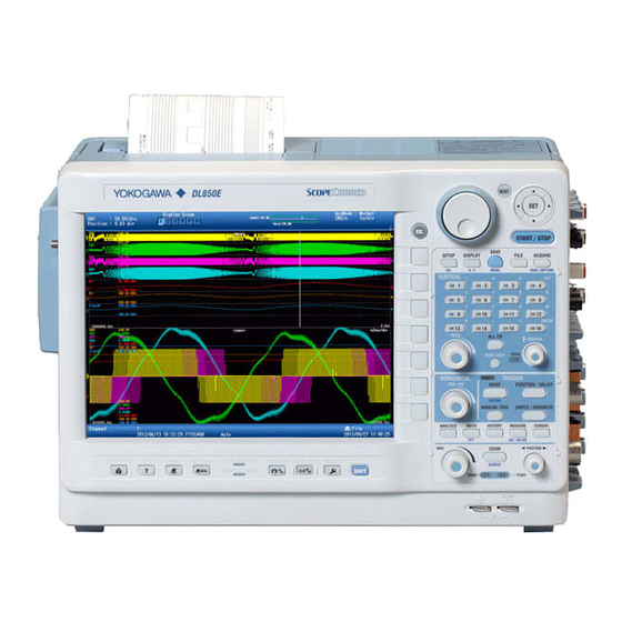
YOKOGAWA DL850 ScopeCorder User Manual (190 pages)
4CH Analog +16 /32bit Logic
Brand:
YOKOGAWA
| Category:
Measuring Instruments
| Size: 20 MB
Table of Contents
Optional Accessories (Sold Separately)
9
Product Registration
2
Checking the Contents of the Package
5
Standard Accessories
6
Separately
8
Table of Contents
9
Isolated Probe
10
Safety Precautions
12
New EU Battery Directive
15
Waste Electrical and Electronic Equipment
15
Symbols and Notation Used in this Manual
16
Table of Contents
17
Chapter 1 Names and Functions of Parts
19
Top Panel, Front Panel, Right Side Panel, and Left Side Panel
19
Front Panel
20
Current Probe
21
Panel Keys and Knobs
24
Help Key
27
Screens
28
System Configuration
30
Measurement Lead
30
Chapter 2 Main Features
31
Vertical and Horizontal Axes
31
Triggering
34
Waveform Acquisition
37
Waveform Display
39
Waveform Computation and Analysis
40
App
41
Chapter 3 Making Preparations for Measurements
42
Handling Precautions
42
Cable.
43
Installing the Instrument
44
Installing Input Modules
46
Connecting to a Power Supply and Turning the Power Switch on and off
50
Index
50
Connecting Probes
55
Correcting the Probe Phase
61
Connecting Measurement Leads
63
Connecting Thermocouples
65
Connecting Bridgeheads
66
Connecting a Logic Probe to the Logic Input Module
69
High-Speed Logic Probe
69
Isolated Logic Probe
70
3.11 Connecting an Acceleration Sensor
71
3.12 Connecting Sensors to the Frequency Module
73
Connecting Wires to the 16-CH Voltage Input Module
75
Connecting Wires to the 16-CH Temperature/Voltage Input Module
77
Connecting a Cable to the CAN Bus Monitor Module
80
Connecting a Cable to the CAN & LIN Bus Monitor Module
81
Attaching the Panel Sheet
82
Loading Roll Paper into the Built-In Printer (Optional)
83
Chapter 4 Common Operations
85
Key and Jog Shuttle Operations
85
Entering Values and Strings
87
Using USB Keyboards and Mouse Devices
89
Connection Procedure
89
Synchronizing the Clock
94
Performing Auto Setup
95
Initializing Settings
97
Calibrating the DL850/DL850V
98
Cal Menu
98
Starting and Stopping Waveform Acquisition
99
Displaying Help
100
Chapter 5 External Signal I/O
101
External Trigger Input (TRIGGER IN)
101
Trigger Output (TRIGGER OUT)
102
External Clock Input (EXT CLK IN)
103
Video Signal Output (VIDEO out (XGA))
104
GO/NO-GO Determination I/O and External Start/Stop Input (EXT I/O)
105
External I/O Cable
105
Output Signal
106
IRIG Signal Input (IRIG Option)
108
Chapter 6 Specifications
108
Signal Input Section
109
Triggering Section
109
Time Axis
111
Display
111
Features
112
Data Storage
113
Fft
118
Built-In Printer
119
Storage
119
USB for Peripherals
119
Sd Memory Card
119
6.10 Auxiliary I/O Section
120
6.11 Computer Interface
122
6.12 General Specifications
123
Bridgehead
124
6.13 Module Specifications
127
6.14 Logic Probe Specifications
159
6.15 16-CH Scanner Box Specifications
160
External Dimensions
161
Appendix
162
Appendix 1 Relationship between the Time Axis Setting, Record Length, and Sample Rate
163
Appendix 2 Relationship between the Record Length and the Acquisition Mode
178
Appendix 3 Default Values
180
Appendix 4 USB Keyboard Key Assignments
185
Appendix 5 Block Diagrams
187
Appendix 6 High-Voltage 100 Ks/S, 16-Bit Isolation Module (with RMS) (701260) Specifications
189
Advertisement
Advertisement
Related Products
YOKOGAWA DL850V ScopeCorder
YOKOGAWA ScopeCorder DL750P
YOKOGAWA ScopeCorder DL750
YOKOGAWA DY040
YOKOGAWA digitalYEWFLO DY080/R2
YOKOGAWA DX104P
YOKOGAWA DX204P
YOKOGAWA DX106P
YOKOGAWA DX102P
YOKOGAWA DAQSTATION DX200P
YOKOGAWA Categories
Measuring Instruments
Test Equipment
Transmitter
Controller
Media Converter
More YOKOGAWA Manuals
Login
Sign In
OR
Sign in with Facebook
Sign in with Google
Upload manual
Upload from disk
Upload from URL