Sign In
Upload
Manuals
Brands
YASKAWA Manuals
Servo Drives
R90FE5A
YASKAWA R90FE5A Manuals
Manuals and User Guides for YASKAWA R90FE5A. We have
1
YASKAWA R90FE5A manual available for free PDF download: User Manual
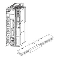
YASKAWA R90FE5A User Manual (332 pages)
AC Servo Drives
Brand:
YASKAWA
| Category:
Servo Drives
| Size: 5 MB
Table of Contents
About this Manual
3
Safety Precautions
7
Warranty
13
Compliance with UL Standards, EU Directives, UK Regulations and Other Safety Standards
15
Table of Contents
18
Chapter 1 Outline
24
Σ-V Series Servopacks
24
Servopacks
24
Part Names
24
SERVOPACK Ratings and Specifications
25
Ratings
25
Basic Specifications
26
SERVOPACK Internal Block Diagrams
29
Single-Phase 100 V, SGDV-R70FE5A, -R90FE5A, -2R1FE5A Models
29
Single-Phase 100 V, SGDV-2R8FE5A Model
30
Three-Phase 200 V, SGDV-R70AE5A, -R90AE5A, -1R6AE5A Models
30
Three-Phase 200 V, SGDV-2R8AE5A Model
31
Three-Phase 200 V, SGDV-3R8AE5A, -5R5AE5A, -7R6AE5A Models
31
Three-Phase 200 V, SGDV-120AE5A Model
32
Three-Phase 200 V, SGDV-180AE5A, -200AE5A Models
32
Three-Phase 200 V, SGDV-330AE5A Model
33
Three-Phase 200 V, SGDV-550AE5A Models
33
Three-Phase 400 V, SGDV-1R9DE5A, -3R5DE5A, -5R4DE5A Models
34
Three-Phase 400 V, SGDV-8R4DE5A, -120DE5A Models
34
Three-Phase 400 V, SGDV-170DE5A Model
35
Three-Phase 400 V, SGDV-260DE5A Model
35
Examples of Servo System Configurations
36
Connecting to SGDV-FE5A SERVOPACK
36
Connecting to SGDV-AE5A SERVOPACK
37
Connecting to SGDV-DE5A SERVOPACK
39
SERVOPACK Model Designation
40
Servo Drive Maintenance and Inspection
41
SERVOPACK Inspection
41
Servopack's Parts Replacement Schedule
41
Servomotor Inspection
42
Chapter 2 Panel Display and Operation of Digital Operator
44
Panel Display
44
Status Display
44
Alarm and Warning Display
44
Hard Wire Base Block Display
44
Overtravel Display
44
Operation of Digital Operator
45
Utility Functions (Fn)
45
Parameters (Pn)
46
Parameter Classification
46
Notation for Parameters
46
Setting Parameters
47
Monitor Displays (Un)
49
Chapter 3 Wiring and Connection
52
Main Circuit Wiring
52
Main Circuit Terminals
52
Using a Standard Power Supply (Single-Phase 100 V, Three-Phase 200 V, or Three-Phase 400 V)
53
Using the SERVOPACK with Single-Phase, 200 V Power Input
61
Using the SERVOPACK with a DC Power Input
64
Using more than One SERVOPACK
68
General Precautions for Wiring
69
I/O Signal Connections
70
I/O Signal (CN1) Names and Functions
70
Safety Function Signal (CN8) Names and Functions
71
Example of I/O Signal Connections
72
I/O Signal Allocations
73
Input Signal Allocations
73
Output Signal Allocations
75
Examples of Connection to Host Controller
76
Sequence Input Circuit
76
Sequence Output Circuit
77
Wiring Communications Using Command Option Modules
79
Linear Scale Connection
80
Linear Scale Signal (CN2) Names and Functions
80
Serial Converter Unit
80
Linear Scale Connection Examples
83
Connecting Regenerative Resistors
87
Setting Regenerative Resistor Capacity
89
Noise Control and Measures for Harmonic Suppression
90
Wiring for Noise Control
90
Noise Filter Wiring and Connection Precautions
92
Connecting a Reactor for Harmonic Suppression
93
Chapter 4 Operation
97
Option Module Function Settings
97
Settings for Common Basic Functions
98
Inspection and Checking before Operation
98
Servomotor Movement Direction
98
Overtravel
100
Electronic Gear
103
Encoder Output Pulses
106
Setting Encoder Output Pulse
112
Holding Brakes
113
Stopping Servomotors after Servo off Command or Alarm Occurrence
117
Instantaneous Power Interruption Settings
119
Motor Maximum Speed
120
SEMI F47 Function
120
Setting Motor Overload Detection Level
123
Test Without Motor Function
125
Motor Information
125
Motor Position and Speed Responses
126
Limitations
126
Digital Operator Displays During Testing Without Motor
127
Limiting Force
128
Internal Force Limit
128
External Force Limit
129
Checking Output Force Limiting During Operation
130
Absolute Linear Scales
131
Absolute Data Request (Sensor on Command)
131
Absolute Data Reception Sequence
132
Other Output Signals
135
Servo Alarm Output Signal (ALM)
135
Warning Output Signal (/WARN)
135
Movement Detection Output Signal (/TGON)
136
Servo Ready Output Signal (/S-RDY)
136
Speed Coincidence Output Signal (/V-CMP)
137
Positioning Completed Output Signal (/COIN)
138
Positioning Near Output Signal (/NEAR)
139
Speed Limit Detection Signal (/VLT)
140
Safety Function
142
Hard Wire Base Block (HWBB) Function
142
External Device Monitor (EDM1)
147
Application Example of Safety Functions
149
Confirming Safety Functions
150
Safety Device Connections
151
Precautions for Safety Functions
152
Chapter 5 Adjustments
155
Type of Adjustments and Basic Adjustment Procedure
155
Adjustments
155
Basic Adjustment Procedure
156
Monitoring Operation During Adjustment
157
Safety Precautions on Adjustment of Servo Gains
160
Tuning-Less Function
162
Tuning-Less Levels Setting (Fn200) Procedure
164
Related Parameters
166
Advanced Autotuning (Fn201)
167
Advanced Autotuning
167
Advanced Autotuning Procedure
170
Related Parameters
176
Advanced Autotuning by Reference (Fn202)
177
Advanced Autotuning by Reference
177
Advanced Autotuning by Reference Procedure
179
Related Parameters
183
One-Parameter Tuning (Fn203)
184
One-Parameter Tuning
184
One-Parameter Tuning Procedure
185
One-Parameter Tuning Example
191
Related Parameters
193
Anti-Resonance Control Adjustment Function (Fn204)
194
Anti-Resonance Control Adjustment Function
194
Anti-Resonance Control Adjustment Function Operating Procedure
195
Related Parameters
199
Vibration Suppression Function (Fn205)
200
Vibration Suppression Function
200
Vibration Suppression Function Operating Procedure
201
Related Parameters
204
Additional Adjustment Function
205
Switching Gain Settings
205
Manual Adjustment of Friction Compensation
209
Current Control Mode Selection Function
211
Current Gain Level Setting
211
Speed Detection Method Selection
211
Compatible Adjustment Function
212
Feedforward Reference
212
Mode Switch (P/PI Switching)
213
Force Reference Filter
215
Position Integral
217
Chapter 6 Utility Functions (Fn)
220
List of Utility Functions
220
Alarm History Display (Fn000)
221
JOG Operation (Fn002)
222
Origin Search (Fn003)
224
Program JOG Operation (Fn004)
226
Initializing Parameter Settings (Fn005)
230
Clearing Alarm History (Fn006)
231
Offset Adjustment of Analog Monitor Output (Fn00C)
232
Gain Adjustment of Analog Monitor Output (Fn00D)
234
Automatic Offset-Signal Adjustment of the Motor Current Detection Signal (Fn00E)
236
Signal (Fn00E)
236
Manual Offset-Signal Adjustment of the Motor Current Detection Signal (Fn00F)
237
Signal (Fn00F)
239
Write Prohibited Setting (Fn010)
239
Servomotor Model Display (Fn011)
241
Software Version Display (Fn012)
242
Resetting Configuration Errors in Option Modules (Fn014)
243
Vibration Detection Level Initialization (Fn01B)
244
Display of SERVOPACK and Servomotor ID (Fn01E)
246
Origin Setting (Fn020)
248
Software Reset (Fn030)
249
Polarity Detection (Fn080)
250
Easyfft (Fn206)
251
Online Vibration Monitor (Fn207)
254
Chapter 7 Monitor Displays (Un)
258
List of Monitor Displays
258
Viewing Monitor Displays
259
Monitoring Input Signals
260
Interpreting Input Signal Display Status
260
Input Signal Display Example
261
Monitoring Input Signals
261
Monitoring Output Signals
262
Interpreting Output Signal Display Status
262
Output Signal Display Example
262
Monitoring Safety Input Signals
263
Interpreting Safety Input Signal Display Status
263
Safety Input Signal Display Example
263
Chapter 8 Troubleshooting
266
Alarm Displays
266
List of Alarms
266
Troubleshooting of Alarms
270
Warning Displays
289
List of Warnings
289
Troubleshooting of Warnings
290
The Servomotor
290
Troubleshooting Malfunction Based on Operation and Conditions
294
Of the Servomotor
295
Chapter 9 Appendix
301
List of Parameters
302
Parameter Recording Table
322
Index
327
Revision History
330
Advertisement
Advertisement
Related Products
YASKAWA R Series
YASKAWA RC5 Series
YASKAWA RM2-755-RDR
YASKAWA RM2-755/1255SL
YASKAWA R1000 Series
YASKAWA 04D
YASKAWA A01
YASKAWA A02
YASKAWA CACP-JU series
YASKAWA CACR-HR BAB Series
YASKAWA Categories
Controller
DC Drives
Servo Drives
Robotics
Inverter
More YASKAWA Manuals
Login
Sign In
OR
Sign in with Facebook
Sign in with Google
Upload manual
Upload from disk
Upload from URL