Sign In
Upload
Manuals
Brands
YASKAWA Manuals
Servo Drives
CIPR-LA70C4039ABA-9600
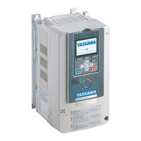
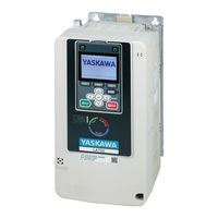
YASKAWA CIPR-LA70C4039ABA-9600 Manuals
Manuals and User Guides for YASKAWA CIPR-LA70C4039ABA-9600. We have
3
YASKAWA CIPR-LA70C4039ABA-9600 manuals available for free PDF download: Technical Manual, Installation And Operation Instruction Manual, Quick Setup
YASKAWA CIPR-LA70C4039ABA-9600 Technical Manual (716 pages)
AC Drive for Elevator Applications
Brand:
YASKAWA
| Category:
Industrial Equipment
| Size: 65 MB
Table of Contents
Table of Contents
3
Preface and General Precautions
13
Receiving
14
Glossary
14
About Registered Trademarks
14
Using the Product Safely
15
Explanation of Signal Words
15
Section Safety
15
Warning Label Content and Location
18
Warranty Information
21
Exclusion of Liability
21
1 Receiving
23
Section Safety
24
Verifying the Drive Model and Nameplate
25
Features and Advantages of Control Methods
28
2 Mechanical Installation
29
Section Safety
30
Installation Environment
32
Installation Position and Clearances
33
Install Single Drive
33
External Heatsink Installation
33
Moving the Drive
35
Using the Hanging Brackets to Move the Drive
35
Instructions on Drive Suspension
35
Drive Watt Loss
37
Drive Watt Loss (Without Built-In EMC Filter)
37
Drive Watt Loss (with Built-In EMC Filter)
38
Remove and Reattach the Keypad
39
Remove the Keypad
39
Reattach the Keypad
39
Install the Keypad in a Control Panel or Another Device
40
Connect the Keypad from a Remote Location
40
Removing/Reattaching Covers
45
Remove the Front Cover (Models: 2022 to 2225 and 4012 to 4188)
45
Install the Front Cover (Models: 2022 to 2225 and 4012 to 4188)
45
Remove the Front Cover (Models: 2269 to 2519 and 4225 to 4380)
46
Reattach the Front Cover (Models: 2269 to 2519 and 4225 to 4380)
47
Remove the Terminal Cover (Models: 2269 to 2519 and 4225 to 4380)
48
Reattach the Terminal Cover (Models: 2269 to 2519 and 4225 to 4380)
48
Installation Methods
50
Standard Installation
50
External Heatsink Installation
50
3 Electrical Installation
53
Section Safety
54
Standard Connection Diagram
56
Main Circuit Wiring
59
Motor and Main Circuit Connections
59
Configuration of Main Circuit Terminal Block
59
Main Circuit Terminal Functions
64
Wire Selection
64
Main Circuit Terminal and Motor Wiring
71
Protection of Main Circuit Terminals
74
Main Circuit Terminal Block Wiring Procedure
75
Wire the Main Circuit Terminal Block
75
Control Circuit Wiring
81
Control Circuit Connection Diagram
81
Control Circuit Terminal Block Functions
82
Control Circuit Terminals
86
Wiring the Control Circuit Terminal
88
Switches and Jumpers on the Terminal Board
90
Control I/O Connections
91
Set Sinking Mode/Sourcing Mode
91
Set Input Signals for MFAI Terminals A1 to A3
91
Set MFAI Terminal A3 to PTC Input
92
Set Output Signals for MFAO Terminals FM, am
92
Switch on Termination Resistor for Memobus/Modbus Communications
92
Connect the Drive to a PC
94
Braking Resistor Installation
95
Install a Braking Resistor Unit: LKEB-Type
95
Install a Braking Unit: CDBR-Type
95
Connect Braking Units in Parallel
99
Dynamic Braking Option Overload Protection
100
Drive Wiring Protection
101
Installing a Residual Current Monitor/Residual Current Device (RCM/RCD)
101
Installing a Molded-Case Circuit Breaker (MCCB) or Residual Current Monitor/Residual Current Device (RCM/RCD)
101
Dynamic Braking Option, Motor Protection
102
Installing an Electromagnetic Contactor (MC) at the Input Side of the Drive
102
Installing a Thermal Overload Relay on the Drive Output
102
Improve the Power Factor
104
Connect an AC Reactor or a DC Reactor
104
Prevent Switching Surge
105
Decrease Noise
106
Connect a Noise Filter to the Input Side (Primary Side)
106
Connect a Noise Filter to the Output Side (Secondary Side)
106
Protect the Drive During Failures
108
Factory-Recommended Branch Circuit Protection for UL Listing
108
Wiring Checklist
110
Motor Application Precautions
111
Precautions for Existing Standard Motors
111
4 Startup Procedure and Test Run
113
Section Safety
114
Keypad Components and Functions
116
LCD Display
117
Indicator Leds and Drive Status
118
Keypad Mode and Menu Displays
120
LED Indicator Status
122
Start-Up Procedures
124
Flowchart A: Connect and Run the Motor with Minimum Setting Changes
124
Sub-Chart A-1: Induction Motor Auto-Tuning and Test Run Procedure
125
Sub-Chart A-2: PM Motor Auto-Tuning and Test Run Procedure
126
Items to Check before Starting up the Drive
129
Check before Energizing the Drive
129
Check after Energizing the Drive
129
Make the Initial Settings
129
Control Method Selection
130
Setting the Motor Rotation Direction
130
Setting the Encoder (Pulse Generator)
131
Keypad Display Unit Selection
131
Keypad Operation
133
Home Screen Display Selection
133
Examine User Custom Parameters
134
Change Parameter Setting Values
135
Check Modified Parameters
136
Restore Modified Parameters to Defaults
137
Show Fault History
139
Show the Monitor
139
Set Custom Monitors
140
Show Custom Monitors
141
Auto-Tuning the Drive
142
Start Data Logging
144
Configuring the Data Log Content
145
Set Backlight to Automatically Turn off
147
Show Information about the Drive
149
Save a Backup of Parameters
150
Write Backed-Up Parameters to the Drive
151
Verify Keypad Parameters and Drive Parameters
152
Delete Parameters Backed up to the Keypad
153
Set the Keypad Language Display
154
Set the Date and Time
155
Set Parameters Using the Setup Wizard
157
Disable the Initial Setup Screen
158
Write Automatically Backed-Up Parameters to the Drive
159
Auto-Tuning
160
Auto-Tuning for Induction Motors
160
Auto-Tuning for Motor Parameters for PM Motor
161
Precautions before Auto-Tuning
162
Rotation Direction Trouble Shoot Function
164
Setup Procedure for Elevator Applications
166
External Interlock
166
Speed Reference Selection and Up/Down Command Selection
166
Speed Selection Using Digital Inputs (B1-01 = 0)
167
Multi-Function Terminal Setup
169
Accel/Decel Ramp and Jerk Settings
170
Elevator Emergency Stop
170
Inspection Operation
171
Brake Sequence
172
Brake Torque Check Function
175
Adjustments for Elevator Ride Comfort
178
Rescue Operation
179
Brake Response Monitor
191
Short Circuit Braking Function
199
Improve Ride Comfort
201
Test Run Checklist
203
5 Standards Compliance
205
Section Safety
206
European Standards
208
CE Low Voltage Directive Compliance
208
EMC Directive
218
United Kingdom Conformity Assessed Marking
225
UL Standards
227
Area of Use
227
Wire the Main Circuit Terminal Block
227
UL Standards Compliance for DC Power Supply Input
238
Low Voltage Wiring for Control Circuit Terminals
240
Drive Motor Overload and Overheat Protection
240
China Rohs Compliance
245
Information on Hazardous Substances in this Product
245
对应中国Rohs指令
246
本产品中含有有害物质的信息
246
Safe Disable Input
247
Safe Disable Specifications
247
Notes
247
Using the Safe Disable Function
248
No Motor Contactor Solution
254
6 Network Communications
255
Section Safety
256
Field Bus Network Support
257
Memobus/Modbus Communications
258
Configure Master/Slave
258
Communication Specifications
258
Communication with the PLC
258
Memobus/Modbus Drive Operations
259
Communications Timing
260
Message Format
261
Examples of Messages for Commands/Responses
263
Enter Command
267
Self-Diagnostics
267
Communications Data Table
268
Error Codes
288
7 Troubleshooting
291
Section Safety
292
Types of Faults, Minor Faults, Alarms, and Errors
294
List of Fault, Minor Fault, Alarm, and Error Codes
295
Fault
300
Minor Faults/Alarms
325
Parameter Setting Errors
334
Auto-Tuning Errors
337
Backup Function Operating Mode Display and Errors
341
Diagnosing and Resetting Faults
342
Fault and Power Loss Occur at the same Time
342
Fault Occurs Without Power Loss
342
Fault Reset
342
Troubleshooting Without Fault Display
343
Typical Problems
343
The Parameter Settings will Not Change
343
The Motor Does Not Rotate after Entering Up/Down Command
344
The Motor Rotates in the Opposite Direction from the Up/Down Command
344
The Motor Is too Hot
345
The Correct Auto-Tuning Mode Is Not Available
345
More
345
Ope02 Error Occurs When Decreasing the Motor Rated Current Setting
345
The Motor Stalls During Acceleration or Accel/Decel Ramp Is too Long
346
Command
346
There Is too Much Motor Oscillation and the Rotation Is Irregular
347
Deceleration Takes Longer than Expected When You Enable Dynamic Braking
347
The Elevator Car Rolls Back When You Apply or Release the Brake
347
Drive
347
Run
347
The Motor Rotation Causes Oscillation or Hunting
348
The Starting Torque Is Not Sufficient
348
The Motor Rotates after the Drive Output Is Shut off
348
The Output Speed Is Lower than the Speed Reference
348
The Motor Speed Is Not Stable When You Use a PM Motor
348
The Motor Is Making an Audible Noise
348
8 Periodic Inspection and Maintenance
349
Section Safety
350
Inspection
352
Recommended Daily Inspection
352
Recommended Periodic Inspection
352
Maintenance
354
Replaceable Parts
354
Part Replacement Guidelines
354
Monitors that Display the Lifespan of Drive Components
354
Alarm Outputs for Maintenance Monitors
355
Related Parameters
355
Replace Cooling Fans and Circulation Fans
356
Cooling Fans and Circulation Fans by Drive Model
356
Fan Replacement (Procedure A)
356
Fan Replacement (Procedure B)
358
Fan Replacement (Procedure C)
360
Fan Replacement (Procedure D)
362
Fan Replacement (Procedure E)
365
Fan Replacement (Procedure F)
367
Replace the Drive
373
About the Control Circuit Terminal Block
373
Drive Replacement
373
Replace the Keypad Battery
378
Storage Guidelines
380
9 Disposal
381
Section Safety
382
Disposal Instructions
383
10 Specifications
385
Section Safety
386
Model Specifications (Three-Phase 200 V Class)
387
Model Specifications (Three-Phase 400 V Class)
389
Drive Specifications
391
Drive Derating
394
Carrier Frequency Settings and Rated Current Values
394
Altitude Derating
395
Drive Exterior and Mounting Dimensions
396
IP20/UL Open Type
396
Peripheral Devices and Options
404
11 Parameter List
407
Section Safety
408
How to Read the Parameter List
409
Parameter Groups
410
A: Initialization Parameters
411
A1: Initialization
411
A2: User Parameters
412
B: Application
415
B1: Operation Mode Selection
415
B2: Magnetic Flux Compensation
415
B4: Timer Function
416
B6: Dwell Function
416
B7: Droop Control
416
B8: Energy Saving
416
C: Tuning
417
C1: Accel & Decel Ramp
417
C2: Jerk Characteristics
418
C3: Slip Compensation
418
C4: Torque Compensation
419
C5: Auto Speed Regulator (ASR)
419
C6: Carrier Frequency
420
D: References
421
D1: Speed Reference
421
D6: Field Forcing
422
E: Motor Parameters
423
E1: V/F Pattern for Motor 1
423
E2: Motor Parameters
424
E3: V/F Pattern for Motor 2
424
E4: Motor 2 Parameters
425
E5: PM Motor Settings
425
F: Options
426
F1: Encoder Option Setup
426
F3: Digital Input Option
429
F4: Analog Output Option
430
F5: Digital Output Option
431
F6: Communication Options
431
11.10 H: Terminal Functions
433
H1: Digital Inputs
433
H1-XX: MFDI Setting Values
434
H2: Digital Outputs
439
H2-XX: MFDO Setting Values
440
H3: Analog Inputs
447
H3-XX: MFAI Setting Values
448
H4: Analog Outputs
449
H5: Serial Communication
449
11.11 L: Protection Functions
451
L1: Motor Protection
451
L2: Undervoltage Detection
451
L3: Stall Prevention
452
L4: Speed Detection
452
L5: Automatic Fault Reset
453
L6: Torque Detection
453
L7: Torque Limit
454
L8: Drive Protection
454
11.12 N: Special Adjustment
456
N1: Hunting Prevention
456
N2: Auto Freq Regulator (AFR)
456
N5: Feed Forward Control
456
N6: Online Tuning
457
N8: PM Motor Control Tuning
457
Na: PM Motor Control Tuning
458
11.13 O: Keypad-Related Settings
459
O1: Keypad Display
459
O2: Keypad Operation
461
O3: Copy Keypad Function
462
O4: Maintenance Monitors
462
O5: Log Function
464
11.14 S: Elevator Parameters
466
S1: Brake/Contactor Sequence
466
S2: Elevator Slip Compensation
466
S3: Start/Stop Optimization
467
S4: Rescue Operation
468
S5: Elevator Functionality
469
S6: Elevator Error Detection
471
11.15 T: Auto-Tuning
473
T0: Tuning Mode Selection
473
T1: Induction Motor Auto-Tuning
473
T2: PM Motor Auto-Tuning
474
11.16 U: Monitors
475
U1: Operation Status Monitors
475
U2: Fault Trace
477
U3: Fault History
480
U4: Maintenance Monitors
481
U6: Operation Status Monitors
486
U9: Fault Trace
488
Parameters that Change from the Default Settings with A1-02
491
Selection]
491
Parameters that Change from the Default Settings with A1-02 [Control Method Selection]
491
Parameters Changed by E1-03 [V/F Pattern Selection]
493
11.19 Defaults by Drive Model
494
Selection]
500
Defaults and Setting Ranges Changed by O1-03 [Speed Display Unit Selection]
500
12 Parameter Details
503
Section Safety
504
A: Initialization Parameters
505
A1: Initialization
505
A2: User Parameters
509
B: Application
511
B1: Operation Mode Selection
511
B2: Magnetic Flux Compensation
516
B4: Timer Function
516
B6: Dwell Function
517
B7: Droop Control
518
B8: Energy Saving
519
C: Tuning
522
C1: Accel & Decel Ramp
522
C2: Jerk Characteristics
527
C3: Slip Compensation
528
C4: Torque Compensation
530
C5: Auto Speed Regulator (ASR)
531
C6: Carrier Frequency
536
D: References
539
D1: Speed Reference
539
D6: Field Forcing
543
E: Motor Parameters
545
E1: V/F Pattern for Motor 1
545
E2: Motor Parameters
547
E3: V/F Pattern for Motor 2
550
E4: Motor 2 Parameters
551
E5: PM Motor Settings
553
F: Options
556
F1: Encoder Option Setup
556
F3: Digital Input Option
565
F4: Analog Monitor Option
570
F5: Digital Output Option
572
F6: Communication Options
575
H: Terminal Functions
578
H1: Digital Inputs
578
MFDI Setting Values
583
H2: Digital Outputs
592
MFDO Setting Values
594
H3: Analog Inputs
607
MFAI Setting Values
611
H4: Analog Outputs
613
H5: Serial Communication
616
L: Protection Functions
620
L1: Motor Protection
620
L2: Undervoltage Detection
625
L3: Stall Prevention
625
L4: Speed Detection
627
L5: Automatic Fault Reset
628
L6: Torque Detection
630
L7: Torque Limit
633
L8: Drive Protection
635
12.10 N: Special Adjustment
642
N1: Hunting Prevention
642
N2: Auto Freq Regulator (AFR)
643
N5: Feed Forward Control
644
N6: Online Tuning
647
N8: PM Motor Control Tuning
648
Na: PM Motor Control Tuning
651
12.11 O: Keypad-Related Settings
652
O1: Keypad Display
652
O2: Keypad Operation
658
O3: Copy Keypad Function
660
O4: Maintenance Monitors
662
O5: Log Function
668
12.12 S: Elevator Parameters
674
S1: Brake/Contactor Sequence
674
S2: Elevator Slip Compensation
676
S3: Start/Stop Optimization
677
S4: Rescue Operation
682
S5: Elevator Functionality
684
S6: Elevator Error Detection
695
12.13 T: Auto-Tuning
700
T0: Tuning Mode Selection
700
T1: Induction Motor Auto-Tuning
700
T2: PM Motor Auto-Tuning
702
Index
706
Revision History
714
Advertisement
YASKAWA CIPR-LA70C4039ABA-9600 Installation And Operation Instruction Manual (378 pages)
AC Drive for Elevator Applications
Brand:
YASKAWA
| Category:
Servo Drives
| Size: 27 MB
Table of Contents
Table of Contents
3
English
10
General Information
10
Qualifications for the Intended User
10
Safety
10
Explanation of Signal Words
10
General Safety Instructions
10
Intended Use
12
Exclusion of Liability
12
Model Number and Nameplate Check
12
Warning Label Content and Location
14
Keypad Overview
16
Mechanical Installation
19
Installation Environment
20
Electrical Installation
20
Standard Connection Diagram
21
Control Circuit Terminals
23
Drive Start-Up
23
Drive Setup Procedure
23
Check before Energizing the Drive
24
Setup Wizard
25
Control Method Selection
25
Setting the Motor Rotation Direction
25
Setting the Encoder (Pulse Generator)
26
Keypad Display Unit Selection
26
Drive Parameters
27
Speed Reference Selection and Up/Down Command Selection
29
Brake Sequence
30
Brake Torque Check Function
31
Inspection Operation
33
Troubleshooting
33
Disposal Instructions
38
European Standards
38
CE Low Voltage Directive Compliance
39
EMC Directive
39
United Kingdom Conformity Assessed Marking
41
Safe Disable Input
42
Safe Disable Specifications
42
Using the Safe Disable Function
43
Deutsch
46
Allgemeine Informationen
46
Anwenderzielgruppe
46
Sicherheit
46
Erläuterung der Signalwörter
46
Allgemeine Sicherheitshinweise
46
Bestimmungsgemäßer Gebrauch
49
Haftungsausschluss
49
Überprüfung von Modellnummer und Typenschild
49
Inhalt und Position von Warnetiketten
51
Bedienteil Übersicht
53
Mechanische Installation
57
Installationsumgebung
57
Elektrische Installation
58
Standard-Anschlussdiagramm
58
Steuerkreisklemmen
60
Inbetriebnahme des Frequenzumrichters
60
Verfahren zur Einrichtung des Frequenzumrichters
60
Prüfungen vor dem Einschalten des Frequenzumrichters
61
Einrichtungsassistent
62
Auswahl Regelverfahren
62
Einstellung der Motordrehrichtung
62
Einstellung des Gebers (Impulsgeber)
63
Bedienteil-Einheiten Auswahl
63
FU-Parameter
64
Auswahl des Drehzahlsollwerts und Auswahl des Auf/Ab-Befehls
67
Bremsfolgesteuerung
68
Funktion zur Überprüfung des Bremsmoments
68
Prüfbetrieb
70
Fehlerbehebung
71
Hinweise zur Entsorgung
76
Europäische Normen
76
Konformität mit der CE-Niederspannungsrichtlinie
77
EMV-Richtlinie
77
Konformitätskennzeichnung für das Vereinigte Königreich
79
Eingang „Sicherer Halt
80
Spezifikationen für „Sicherer Halt
80
Verwenden der Funktion „Sicherer Halt
82
Français
84
Informations Générales
84
Qualifications de L'utilisateur Visé
84
Sécurité
85
Explication de la Signalétique
85
Consignes Générales de Sécurité
85
Utilisation Prévue
87
Exclusion de Responsabilité
87
Vérification du Numéro de Modèle et de la Plaque Signalétique
87
Contenu et Emplacement de L'étiquette D'avertissement
89
Aperçu de la Console Numérique
91
Installation Mécanique
94
Environnement D'installation
95
Installation Électrique
95
Schéma de Connexion Standard
96
Borniers du Circuit de Commande
98
Démarrage du Variateur de Vitesse
98
Procédure de Configuration du Variateur
98
À Vérifier Avant la Mise Sous Tension du Variateur
99
Assistant de Configuration
100
Sélection de la Méthode de Commande
100
Réglage du Sens de Rotation du Moteur
100
Réglage du Codeur (Générateur D'impulsions)
101
Sélection de L'unité D'affichage de la Console Numérique
101
Paramètres du Variateur de Vitesse
102
Sélection de la Référence de Vitesse et Sélection de la Commande Vers le Haut/Bas
105
Séquence de Freinage
106
Fonction Vérifier le Couple de Freinage
106
Opération D'inspection
108
Dépannage
108
Instructions de Traitement
113
Normes Européennes
114
Conformité à la Directive Basse Tension CE
114
Directive CEM
115
Marquage de Conformité du Royaume-Uni
117
Entrée de Mise en Sécurité
118
Spécifications de Mise en Sécurité
118
Utilisation de la Fonction D'arrêt de Sécurité
119
Italiano
122
Informazioni Generiche
122
Qualifiche Per L'utente
122
Sicurezza
122
Descrizione Dei Segnali DI Avvertimento
122
Istruzioni Generali DI Sicurezza
123
Uso Previsto
125
Esclusione DI Responsabilità
125
Controllo del Numero DI Modello E Della Targhetta Identificativa
125
Contenuto Dell'etichetta DI Avvertenza E Posizione
127
Panoramica Tastierino
129
Installazione Meccanica
132
Ambiente DI Installazione
133
Installazione Elettrica
133
Schema Connessione Standard
134
Morsetti del Circuito DI Controllo
136
Avvio Dell'inverter
136
Procedura DI Messa in Funzione
136
Controllo Prima Dell'alimentazione Dell'inverter
137
Procedura Guidata Config
138
Selezione Metodo Controllo
138
Impostazione Della Direzione DI Rotazione del Motore
138
Impostazione Dell'encoder (Generatore DI Impulsi)
139
Selezione Unità Display Tastiera
139
Parametri Inverter
140
Selezione Riferimento DI Velocità E Selezione Comando Su/Giù
143
Sequenza DI Frenata
143
Funzione Controllo Coppia Frenante
144
Funzione Ispezione
146
Individuazione Dei Guasti
146
Istruzioni Per lo Smaltimento
151
Norme Europee
152
Conformità alle Direttive CE Sulla Bassa Tensione
152
Direttiva EMC
153
Marchio United Kingdom Conformity Assessed
154
Ingresso Disabilitazione Sicura
155
Specifiche Disabilitazione Sicura
156
Utilizzo Della Funzione Disabilitazione Sicura
157
Español
160
Información General
160
Cualificaciones del Usuario Previsto
160
Seguridad
160
Explicación de Los Términos Indicativos
160
Instrucciones de Seguridad Generales
160
Uso Previsto
163
Exclusión de Responsabilidad
163
Comprobación del Número de Modelo y de la Placa de Características
163
Contenido y Ubicación del Rótulo de Advertencia
165
Vista General del Teclado
167
Instalación Mecánica
171
Lugar de Instalación
171
Instalación Eléctrica
172
Diagrama de Conexión Estándar
172
Terminales del Circuito de Control
174
Puesta en Marcha del Variador
174
Procedimiento de Configuración del Variador
174
Comprobación Antes de Encender el Variador
175
Asistente de Configuración
176
Selección del Método de Control
176
Ajuste de la Dirección de Rotación del Motor
176
Ajuste del Codificador (Generador de Pulsos)
177
Selección de la Unidad de Visualización del Teclado
177
Parámetros del Variador
178
Selección de la Referencia de Velocidad y Selección del Comando Arriba/Abajo
181
Secuencia de Freno
181
Función de Comprobación del Par de Freno
182
Operación de Inspección
184
Solución de Problemas
184
Instrucciones para el Desecho
189
Normas Europeas
189
Cumplimiento de la Directiva de Baja Tensión CE
190
Directiva CEM
191
Marcado de Evaluación de Conformidad del Reino Unido
192
Entrada de Desactivación Segura
193
Especificaciones de la Desactivación Segura
193
Uso de la Función de Desactivación Segura
195
Čeština
198
Všeobecné Informace
198
Kvalifikace Pro Určeného Uživatele
198
Bezpečnost
198
Vysvětlení Signálních Slov
198
Všeobecné Bezpečnostní Pokyny
198
Určené Použití
200
Vyloučení Zodpovědnosti
201
Číslo Modelu a Typový Štítek
201
Obsah a Umístění Výstražného Štítku
202
Přehled Klávesnice
204
Mechanická Instalace
207
Prostředí Pro Instalaci
208
Elektrická Instalace
208
Standardní Schéma Zapojení
209
Svorky ŘíDICího Obvodu
211
Uvedení Měniče Do Chodu
211
Postup Nastavení Měniče
211
Kontrola Před PřipojeníM Napájení Měniče
212
Průvodce NastaveníM
213
Volba Způsobu Řízení
213
Nastavení Směru Otáčení Motoru
213
Nastavení Snímače Polohy (Pulsní Generátor)
214
Volba Jednotky Displeje Klávesnice
214
Parametry Měniče
215
Volba Referenčních Otáček a Volba Povelu Nahoru/Dolů
218
Sekvence Brzdění
218
Funkce Kontroly Brzdného Momentu
219
Kontrolní Provoz
221
Odstraňování Poruch
221
Pokyny K Likvidaci
226
Evropské Normy
226
Soulad Se Směrnicí CE Pro Nízká Napětí
227
Směrnice EMC
227
Označení Shody Pro Velkou Británii
229
Vstup Bezpečné Deaktivace
230
Specifikace Bezpečné Deaktivace
230
Použití Funkce Bezpečného Vypnutí
232
Polski
234
Informacje Ogólne
234
Kwalifikacje Użytkownika
234
Bezpieczeństwo
234
Opis Ostrzeżeń
234
Ogólne Zalecenia Dotyczące Bezpieczeństwa
235
Zastosowanie
237
Wyłączenie OdpowiedzialnośCI
237
Oznaczenie Modelu Przemiennika I Tabliczka Znamionowa
237
Treść I Lokalizacja Etykiety Ostrzegawczej
239
Omówienie Klawiatury
241
Instalacja Mechaniczna
244
Środowisko Instalacji
245
Instalacja Elektryczna
245
Standardowy Schemat Połączeń
246
Zaciski Obwodu Sterującego
248
Uruchamianie Przemiennika
248
Procedura Ustawiania Przemiennika
248
Sprawdzenia Przed Włączeniem Zasilania Przemiennika
249
Kreator Konfiguracji
250
Wybór Metody Sterowania
250
Ustawienie Kierunku Obrotów Silnika
250
Konfiguracja Przetwornika (Generatora Impulsów)
251
Wybór Jednostek Wyświetlania Na Klawiaturze
251
Parametry Przemiennika
252
Wybór PrędkośCI Zadanej I Wybór Polecenia Do Góry/Na Dół
255
Sekwencja Hamowania
256
Funkcja Sprawdzania Momentu Obrotowego Hamowania
256
Działanie Kontrolne
258
Rozwiązywanie Problemów
259
Zalecenia Dotyczące Utylizacji
263
Normy Europejskie
264
Oznaczenie CE ZgodnośCI Z Dyrektywą Niskonapięciową
264
Dyrektywa KompatybilnośCI Elektromagnetycznej
265
Znak Oceny ZgodnośCI W Wielkiej Brytanii
267
Wejście Bezpiecznego Wyłączania
268
Specyfikacje Bezpiecznego Wyłączania
268
Korzystanie Z Funkcji Bezpiecznego Wyłączenia
269
Türkçe
272
Genel Bilgi
272
Hedef KullanıCıda Aranan Niteliklikler
272
Güvenlik
272
Sinyal Kelimelerinin Açıklaması
272
Genel Güvenlik Talimatları
273
KullanıM Amacı
275
Yükümlülük İstisnası
275
Model Numarası Ve İsim Plakası Kontrolü
275
Uyarı Etiketi İçeriğI Ve Konumu
277
Tuş TakıMına Genel Bakış
279
Mekanik Kurulum
282
Kurulum Ortamı
283
Elektriksel Kurulum
283
Standart Bağlantı Şeması
284
Kontrol Devresi Terminalleri
286
SürüCü Çalıştırma
286
SürüCü Kurulum Prosedürü
286
SürüCüye Enerji Vermeden Önce Kontrol Edin
287
Ayar Sihirbazı
288
Kontrol Metodu SeçIMI
288
Motor Dönüş Yönünün Ayarlanması
288
Enkoderin Ayarlanması (Puls Üreteci)
289
Tuş TakıMı Ekran Birimi SeçIMI
289
SürüCü Parametreleri
290
Hız Referansı SeçIMI Ve Yukarı/Aşağı Komut SeçIMI
293
Fren Sırası
293
Fren Tork Kontrol Fonksiyonu
294
İnceleme İşlemi
296
Sorun Giderme
296
İmha Talimatları
301
Avrupa Standartları
301
CE Düşük Gerilim Direktifi Uyumu
302
EMC Direktifi
302
Birleşik Krallık Uygunluk Değerlendirmeli İşaretleme
304
Güvenli Devredışı Bırakma GirişI
305
Güvenli Devredışı Bırakma Özellikleri
305
Güvenli Devredışı Bırakma Fonksiyonunu Kullanma
307
Русский
309
Общая Информация
309
Квалификация Пользователя
309
Безопасность
309
Значение Сигнальных Слов
309
Общие Правила Техники Безопасности
310
Назначение
312
Отказ От Ответственности
312
Проверка Номера Модели И Данных По Паспортной Табличке
313
Содержание И Расположение Предупредительной Этикетки
314
Обзор Пульта Управления
316
Механический Монтаж
320
Среда Установки
320
Электрический Монтаж
321
Стандартная Схема Соединений
321
Клеммы Цепи Управления
323
Запуск Привода
323
Процедура Настройки Привода
323
Проверка Перед Подачей Питания На Привод
324
Мастер Настройки
325
Выбор Метода Управления
325
Настройка Направления Вращения Двигателя
325
Настройка Энкодера (Генератора Импульсов)
326
Выбор Единиц Отображения Для Дисплей На Пульте Оператора
326
Параметры Привода
327
Выбор Задания Скорости И Команды "Вверх/Вниз
330
Последовательность Торможения
331
Функция Проверки Тормозного Момента
331
Операция Проверки
334
Поиск И Устранение Неисправностей
334
Инструкции По Утилизации
339
Европейские Стандарты
340
Соответствие Директиве ЕС По Низковольтному Оборудованию
340
Директива По Электромагнитной Совместимости
341
Маркировка Подтверждения Соответствия Соединенного Королевства
343
Вход Безопасной Блокировки
344
Характеристики Функции Безопасной Блокировки
344
Применение Функции Безопасной Блокировки
346
Attachment
349
UL Standards
349
Area of Use
349
Wire the Main Circuit Terminal Block
349
China Rohs Compliance
359
对应中国Rohs指令
359
CE-Compliant Fuse and RCM/RCD (Input Side)
360
CE Standards Compliance for DC Power Supply Input
361
Wire Selection
363
Main Circuit Wire Gauges and Tightening Torques for UL Compliance
363
Main Circuit Wire Gauges and Tightening Torques for CE Compliance
370
Revision History
377
YASKAWA CIPR-LA70C4039ABA-9600 Quick Setup (4 pages)
Brand:
YASKAWA
| Category:
Industrial Equipment
| Size: 9 MB
Advertisement
Advertisement
Related Products
YASKAWA CIPR-LA70C4023ABA-9600
YASKAWA CIPR-LA70C4019ABA-9600
YASKAWA CIPR-LA70C4012ABA-9600
YASKAWA CIPR-LA70C 9600 Series
Yaskawa CACR-SR20BB
Yaskawa CACR-SR44BB
YASKAWA CACR-HR BB Series
YASKAWA SERVOPACK CACR-SR03AB1FR
YASKAWA SERVOPACK CACR-SR05AB1ER
YASKAWA SERVOPACK CACR-SR05AB1ERY3
YASKAWA Categories
Controller
DC Drives
Servo Drives
Robotics
Inverter
More YASKAWA Manuals
Login
Sign In
OR
Sign in with Facebook
Sign in with Google
Upload manual
Upload from disk
Upload from URL