Sign In
Upload
Manuals
Brands
YASKAWA Manuals
Industrial Equipment
CIPR-LA70C4030ABA-9600
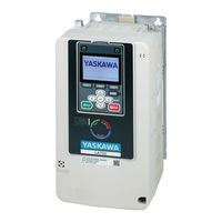
YASKAWA CIPR-LA70C4030ABA-9600 Manuals
Manuals and User Guides for YASKAWA CIPR-LA70C4030ABA-9600. We have
2
YASKAWA CIPR-LA70C4030ABA-9600 manuals available for free PDF download: Technical Manual, Quick Setup
YASKAWA CIPR-LA70C4030ABA-9600 Technical Manual (716 pages)
AC Drive for Elevator Applications
Brand:
YASKAWA
| Category:
Industrial Equipment
| Size: 65 MB
Table of Contents
Table of Contents
3
Preface and General Precautions
13
Receiving
14
Glossary
14
About Registered Trademarks
14
Using the Product Safely
15
Explanation of Signal Words
15
Section Safety
15
Warning Label Content and Location
18
Warranty Information
21
Exclusion of Liability
21
1 Receiving
23
Section Safety
24
Verifying the Drive Model and Nameplate
25
Features and Advantages of Control Methods
28
2 Mechanical Installation
29
Section Safety
30
Installation Environment
32
Installation Position and Clearances
33
Install Single Drive
33
External Heatsink Installation
33
Moving the Drive
35
Using the Hanging Brackets to Move the Drive
35
Instructions on Drive Suspension
35
Drive Watt Loss
37
Drive Watt Loss (Without Built-In EMC Filter)
37
Drive Watt Loss (with Built-In EMC Filter)
38
Remove and Reattach the Keypad
39
Remove the Keypad
39
Reattach the Keypad
39
Install the Keypad in a Control Panel or Another Device
40
Connect the Keypad from a Remote Location
40
Removing/Reattaching Covers
45
Remove the Front Cover (Models: 2022 to 2225 and 4012 to 4188)
45
Install the Front Cover (Models: 2022 to 2225 and 4012 to 4188)
45
Remove the Front Cover (Models: 2269 to 2519 and 4225 to 4380)
46
Reattach the Front Cover (Models: 2269 to 2519 and 4225 to 4380)
47
Remove the Terminal Cover (Models: 2269 to 2519 and 4225 to 4380)
48
Reattach the Terminal Cover (Models: 2269 to 2519 and 4225 to 4380)
48
Installation Methods
50
Standard Installation
50
External Heatsink Installation
50
3 Electrical Installation
53
Section Safety
54
Standard Connection Diagram
56
Main Circuit Wiring
59
Motor and Main Circuit Connections
59
Configuration of Main Circuit Terminal Block
59
Main Circuit Terminal Functions
64
Wire Selection
64
Main Circuit Terminal and Motor Wiring
71
Protection of Main Circuit Terminals
74
Main Circuit Terminal Block Wiring Procedure
75
Wire the Main Circuit Terminal Block
75
Control Circuit Wiring
81
Control Circuit Connection Diagram
81
Control Circuit Terminal Block Functions
82
Control Circuit Terminals
86
Wiring the Control Circuit Terminal
88
Switches and Jumpers on the Terminal Board
90
Control I/O Connections
91
Set Sinking Mode/Sourcing Mode
91
Set Input Signals for MFAI Terminals A1 to A3
91
Set MFAI Terminal A3 to PTC Input
92
Set Output Signals for MFAO Terminals FM, am
92
Switch on Termination Resistor for Memobus/Modbus Communications
92
Connect the Drive to a PC
94
Braking Resistor Installation
95
Install a Braking Resistor Unit: LKEB-Type
95
Install a Braking Unit: CDBR-Type
95
Connect Braking Units in Parallel
99
Dynamic Braking Option Overload Protection
100
Drive Wiring Protection
101
Installing a Residual Current Monitor/Residual Current Device (RCM/RCD)
101
Installing a Molded-Case Circuit Breaker (MCCB) or Residual Current Monitor/Residual Current Device (RCM/RCD)
101
Dynamic Braking Option, Motor Protection
102
Installing an Electromagnetic Contactor (MC) at the Input Side of the Drive
102
Installing a Thermal Overload Relay on the Drive Output
102
Improve the Power Factor
104
Connect an AC Reactor or a DC Reactor
104
Prevent Switching Surge
105
Decrease Noise
106
Connect a Noise Filter to the Input Side (Primary Side)
106
Connect a Noise Filter to the Output Side (Secondary Side)
106
Protect the Drive During Failures
108
Factory-Recommended Branch Circuit Protection for UL Listing
108
Wiring Checklist
110
Motor Application Precautions
111
Precautions for Existing Standard Motors
111
4 Startup Procedure and Test Run
113
Section Safety
114
Keypad Components and Functions
116
LCD Display
117
Indicator Leds and Drive Status
118
Keypad Mode and Menu Displays
120
LED Indicator Status
122
Start-Up Procedures
124
Flowchart A: Connect and Run the Motor with Minimum Setting Changes
124
Sub-Chart A-1: Induction Motor Auto-Tuning and Test Run Procedure
125
Sub-Chart A-2: PM Motor Auto-Tuning and Test Run Procedure
126
Items to Check before Starting up the Drive
129
Check before Energizing the Drive
129
Check after Energizing the Drive
129
Make the Initial Settings
129
Control Method Selection
130
Setting the Motor Rotation Direction
130
Setting the Encoder (Pulse Generator)
131
Keypad Display Unit Selection
131
Keypad Operation
133
Home Screen Display Selection
133
Examine User Custom Parameters
134
Change Parameter Setting Values
135
Check Modified Parameters
136
Restore Modified Parameters to Defaults
137
Show Fault History
139
Show the Monitor
139
Set Custom Monitors
140
Show Custom Monitors
141
Auto-Tuning the Drive
142
Start Data Logging
144
Configuring the Data Log Content
145
Set Backlight to Automatically Turn off
147
Show Information about the Drive
149
Save a Backup of Parameters
150
Write Backed-Up Parameters to the Drive
151
Verify Keypad Parameters and Drive Parameters
152
Delete Parameters Backed up to the Keypad
153
Set the Keypad Language Display
154
Set the Date and Time
155
Set Parameters Using the Setup Wizard
157
Disable the Initial Setup Screen
158
Write Automatically Backed-Up Parameters to the Drive
159
Auto-Tuning
160
Auto-Tuning for Induction Motors
160
Auto-Tuning for Motor Parameters for PM Motor
161
Precautions before Auto-Tuning
162
Rotation Direction Trouble Shoot Function
164
Setup Procedure for Elevator Applications
166
External Interlock
166
Speed Reference Selection and Up/Down Command Selection
166
Speed Selection Using Digital Inputs (B1-01 = 0)
167
Multi-Function Terminal Setup
169
Accel/Decel Ramp and Jerk Settings
170
Elevator Emergency Stop
170
Inspection Operation
171
Brake Sequence
172
Brake Torque Check Function
175
Adjustments for Elevator Ride Comfort
178
Rescue Operation
179
Brake Response Monitor
191
Short Circuit Braking Function
199
Improve Ride Comfort
201
Test Run Checklist
203
5 Standards Compliance
205
Section Safety
206
European Standards
208
CE Low Voltage Directive Compliance
208
EMC Directive
218
United Kingdom Conformity Assessed Marking
225
UL Standards
227
Area of Use
227
Wire the Main Circuit Terminal Block
227
UL Standards Compliance for DC Power Supply Input
238
Low Voltage Wiring for Control Circuit Terminals
240
Drive Motor Overload and Overheat Protection
240
China Rohs Compliance
245
Information on Hazardous Substances in this Product
245
对应中国Rohs指令
246
本产品中含有有害物质的信息
246
Safe Disable Input
247
Safe Disable Specifications
247
Notes
247
Using the Safe Disable Function
248
No Motor Contactor Solution
254
6 Network Communications
255
Section Safety
256
Field Bus Network Support
257
Memobus/Modbus Communications
258
Configure Master/Slave
258
Communication Specifications
258
Communication with the PLC
258
Memobus/Modbus Drive Operations
259
Communications Timing
260
Message Format
261
Examples of Messages for Commands/Responses
263
Enter Command
267
Self-Diagnostics
267
Communications Data Table
268
Error Codes
288
7 Troubleshooting
291
Section Safety
292
Types of Faults, Minor Faults, Alarms, and Errors
294
List of Fault, Minor Fault, Alarm, and Error Codes
295
Fault
300
Minor Faults/Alarms
325
Parameter Setting Errors
334
Auto-Tuning Errors
337
Backup Function Operating Mode Display and Errors
341
Diagnosing and Resetting Faults
342
Fault and Power Loss Occur at the same Time
342
Fault Occurs Without Power Loss
342
Fault Reset
342
Troubleshooting Without Fault Display
343
Typical Problems
343
The Parameter Settings will Not Change
343
The Motor Does Not Rotate after Entering Up/Down Command
344
The Motor Rotates in the Opposite Direction from the Up/Down Command
344
The Motor Is too Hot
345
The Correct Auto-Tuning Mode Is Not Available
345
More
345
Ope02 Error Occurs When Decreasing the Motor Rated Current Setting
345
The Motor Stalls During Acceleration or Accel/Decel Ramp Is too Long
346
Command
346
There Is too Much Motor Oscillation and the Rotation Is Irregular
347
Deceleration Takes Longer than Expected When You Enable Dynamic Braking
347
The Elevator Car Rolls Back When You Apply or Release the Brake
347
Drive
347
Run
347
The Motor Rotation Causes Oscillation or Hunting
348
The Starting Torque Is Not Sufficient
348
The Motor Rotates after the Drive Output Is Shut off
348
The Output Speed Is Lower than the Speed Reference
348
The Motor Speed Is Not Stable When You Use a PM Motor
348
The Motor Is Making an Audible Noise
348
8 Periodic Inspection and Maintenance
349
Section Safety
350
Inspection
352
Recommended Daily Inspection
352
Recommended Periodic Inspection
352
Maintenance
354
Replaceable Parts
354
Part Replacement Guidelines
354
Monitors that Display the Lifespan of Drive Components
354
Alarm Outputs for Maintenance Monitors
355
Related Parameters
355
Replace Cooling Fans and Circulation Fans
356
Cooling Fans and Circulation Fans by Drive Model
356
Fan Replacement (Procedure A)
356
Fan Replacement (Procedure B)
358
Fan Replacement (Procedure C)
360
Fan Replacement (Procedure D)
362
Fan Replacement (Procedure E)
365
Fan Replacement (Procedure F)
367
Replace the Drive
373
About the Control Circuit Terminal Block
373
Drive Replacement
373
Replace the Keypad Battery
378
Storage Guidelines
380
9 Disposal
381
Section Safety
382
Disposal Instructions
383
10 Specifications
385
Section Safety
386
Model Specifications (Three-Phase 200 V Class)
387
Model Specifications (Three-Phase 400 V Class)
389
Drive Specifications
391
Drive Derating
394
Carrier Frequency Settings and Rated Current Values
394
Altitude Derating
395
Drive Exterior and Mounting Dimensions
396
IP20/UL Open Type
396
Peripheral Devices and Options
404
11 Parameter List
407
Section Safety
408
How to Read the Parameter List
409
Parameter Groups
410
A: Initialization Parameters
411
A1: Initialization
411
A2: User Parameters
412
B: Application
415
B1: Operation Mode Selection
415
B2: Magnetic Flux Compensation
415
B4: Timer Function
416
B6: Dwell Function
416
B7: Droop Control
416
B8: Energy Saving
416
C: Tuning
417
C1: Accel & Decel Ramp
417
C2: Jerk Characteristics
418
C3: Slip Compensation
418
C4: Torque Compensation
419
C5: Auto Speed Regulator (ASR)
419
C6: Carrier Frequency
420
D: References
421
D1: Speed Reference
421
D6: Field Forcing
422
E: Motor Parameters
423
E1: V/F Pattern for Motor 1
423
E2: Motor Parameters
424
E3: V/F Pattern for Motor 2
424
E4: Motor 2 Parameters
425
E5: PM Motor Settings
425
F: Options
426
F1: Encoder Option Setup
426
F3: Digital Input Option
429
F4: Analog Output Option
430
F5: Digital Output Option
431
F6: Communication Options
431
11.10 H: Terminal Functions
433
H1: Digital Inputs
433
H1-XX: MFDI Setting Values
434
H2: Digital Outputs
439
H2-XX: MFDO Setting Values
440
H3: Analog Inputs
447
H3-XX: MFAI Setting Values
448
H4: Analog Outputs
449
H5: Serial Communication
449
11.11 L: Protection Functions
451
L1: Motor Protection
451
L2: Undervoltage Detection
451
L3: Stall Prevention
452
L4: Speed Detection
452
L5: Automatic Fault Reset
453
L6: Torque Detection
453
L7: Torque Limit
454
L8: Drive Protection
454
11.12 N: Special Adjustment
456
N1: Hunting Prevention
456
N2: Auto Freq Regulator (AFR)
456
N5: Feed Forward Control
456
N6: Online Tuning
457
N8: PM Motor Control Tuning
457
Na: PM Motor Control Tuning
458
11.13 O: Keypad-Related Settings
459
O1: Keypad Display
459
O2: Keypad Operation
461
O3: Copy Keypad Function
462
O4: Maintenance Monitors
462
O5: Log Function
464
11.14 S: Elevator Parameters
466
S1: Brake/Contactor Sequence
466
S2: Elevator Slip Compensation
466
S3: Start/Stop Optimization
467
S4: Rescue Operation
468
S5: Elevator Functionality
469
S6: Elevator Error Detection
471
11.15 T: Auto-Tuning
473
T0: Tuning Mode Selection
473
T1: Induction Motor Auto-Tuning
473
T2: PM Motor Auto-Tuning
474
11.16 U: Monitors
475
U1: Operation Status Monitors
475
U2: Fault Trace
477
U3: Fault History
480
U4: Maintenance Monitors
481
U6: Operation Status Monitors
486
U9: Fault Trace
488
Parameters that Change from the Default Settings with A1-02
491
Selection]
491
Parameters that Change from the Default Settings with A1-02 [Control Method Selection]
491
Parameters Changed by E1-03 [V/F Pattern Selection]
493
11.19 Defaults by Drive Model
494
Selection]
500
Defaults and Setting Ranges Changed by O1-03 [Speed Display Unit Selection]
500
12 Parameter Details
503
Section Safety
504
A: Initialization Parameters
505
A1: Initialization
505
A2: User Parameters
509
B: Application
511
B1: Operation Mode Selection
511
B2: Magnetic Flux Compensation
516
B4: Timer Function
516
B6: Dwell Function
517
B7: Droop Control
518
B8: Energy Saving
519
C: Tuning
522
C1: Accel & Decel Ramp
522
C2: Jerk Characteristics
527
C3: Slip Compensation
528
C4: Torque Compensation
530
C5: Auto Speed Regulator (ASR)
531
C6: Carrier Frequency
536
D: References
539
D1: Speed Reference
539
D6: Field Forcing
543
E: Motor Parameters
545
E1: V/F Pattern for Motor 1
545
E2: Motor Parameters
547
E3: V/F Pattern for Motor 2
550
E4: Motor 2 Parameters
551
E5: PM Motor Settings
553
F: Options
556
F1: Encoder Option Setup
556
F3: Digital Input Option
565
F4: Analog Monitor Option
570
F5: Digital Output Option
572
F6: Communication Options
575
H: Terminal Functions
578
H1: Digital Inputs
578
MFDI Setting Values
583
H2: Digital Outputs
592
MFDO Setting Values
594
H3: Analog Inputs
607
MFAI Setting Values
611
H4: Analog Outputs
613
H5: Serial Communication
616
L: Protection Functions
620
L1: Motor Protection
620
L2: Undervoltage Detection
625
L3: Stall Prevention
625
L4: Speed Detection
627
L5: Automatic Fault Reset
628
L6: Torque Detection
630
L7: Torque Limit
633
L8: Drive Protection
635
12.10 N: Special Adjustment
642
N1: Hunting Prevention
642
N2: Auto Freq Regulator (AFR)
643
N5: Feed Forward Control
644
N6: Online Tuning
647
N8: PM Motor Control Tuning
648
Na: PM Motor Control Tuning
651
12.11 O: Keypad-Related Settings
652
O1: Keypad Display
652
O2: Keypad Operation
658
O3: Copy Keypad Function
660
O4: Maintenance Monitors
662
O5: Log Function
668
12.12 S: Elevator Parameters
674
S1: Brake/Contactor Sequence
674
S2: Elevator Slip Compensation
676
S3: Start/Stop Optimization
677
S4: Rescue Operation
682
S5: Elevator Functionality
684
S6: Elevator Error Detection
695
12.13 T: Auto-Tuning
700
T0: Tuning Mode Selection
700
T1: Induction Motor Auto-Tuning
700
T2: PM Motor Auto-Tuning
702
Index
706
Revision History
714
Advertisement
YASKAWA CIPR-LA70C4030ABA-9600 Quick Setup (4 pages)
Brand:
YASKAWA
| Category:
Industrial Equipment
| Size: 9 MB
Advertisement
Related Products
YASKAWA CIMR-R5U20181A
YASKAWA CIMR-R5U20221A
YASKAWA CIMR-R5U20301A
YASKAWA CIMR-R5U20370A
YASKAWA CIMR-R5U47P51A
YASKAWA CIMR-R5U40111A
YASKAWA CIMR-R5U40151A
YASKAWA CIMR-R5U40370A
YASKAWA CIMR-R5U40550A
YASKAWA CIMR-E7C47P5
YASKAWA Categories
Controller
DC Drives
Servo Drives
Robotics
Inverter
More YASKAWA Manuals
Login
Sign In
OR
Sign in with Facebook
Sign in with Google
Upload manual
Upload from disk
Upload from URL