Sign In
Upload
Manuals
Brands
YASKAWA Manuals
DC Drives
CIPR-CR70C Series
YASKAWA CIPR-CR70C Series Manuals
Manuals and User Guides for YASKAWA CIPR-CR70C Series. We have
1
YASKAWA CIPR-CR70C Series manual available for free PDF download: Technical Manual
YASKAWA CIPR-CR70C Series Technical Manual (894 pages)
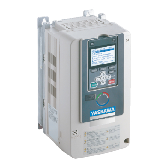
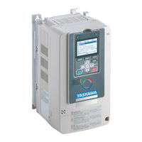
AC Drive
Brand:
YASKAWA
| Category:
DC Drives
| Size: 85 MB
Table of Contents
Table of Contents
3
Preface and General Precautions
13
Receiving
14
Glossary
14
Registered Trademarks
14
Using the Product Safely
15
Explanation of Signal Words
15
Section Safety
15
Warning Label Content and Locations
17
Warranty Information
18
Exclusion of Liability
18
Receiving
19
Section Safety
20
Crane Application Instructions
21
Model Number and Nameplate Check
22
Nameplate
22
How to Read the Model Number
22
Control Method Type and Corresponding Features
26
Mechanical & Electrical Installation
29
Section Safety
30
Installation Environment
33
Installation Orientation and Spacing
34
Moving the Drive
36
Using the Hanging Brackets to Move the Drive
36
Instructions on Drive Suspension
36
Drive Watt Loss
38
Remove and Reattach the Keypad
40
Remove the Keypad
40
Reattach the Keypad
40
Install the Keypad in a Control Panel or Another Device
41
Operate the Keypad from a Remote Location
41
Connect the Keypad from a Remote Location
41
Removing/Reattaching Covers
46
Removing/Reattaching the Cover Using Procedure a
46
Removing/Reattaching the Cover Using Procedure B
47
Change the Drive Enclosure Type
51
Remove the Knock-Out Holes
51
Attach the Protective Cover (Procedure A)
51
Attach the Protective Cover (Procedure B)
53
Attach the Protective Cover (Procedure C)
55
Attach the Protective Cover (Procedure D)
56
Attach the Protective Cover (Procedure E)
58
Attach the Protective Cover (Procedure F)
61
Attach the Protective Cover (Procedure G)
64
Installation Methods
67
Electrical Installation
71
Standard Connection Diagram
71
Main Circuit Wiring
74
Motor and Main Circuit Connections
74
Configuration of Main Circuit Terminal Block
74
Main Circuit Terminal Functions
79
Main Circuit Wire Gauges and Tightening Torques
80
Main Circuit Terminal and Motor Wiring
90
Protection of Main Circuit Terminals
93
Main Circuit Terminal Block Wiring Procedure
94
Wire the Main Circuit Terminal Block with Procedure a
94
Wire the Main Circuit Terminal Block with Procedure B
97
Control Circuit Wiring
100
Control Circuit Connection Diagram
100
Control Circuit Terminal Block Functions
101
Terminal Configuration
106
Wiring the Control Circuit Terminal
108
Switches and Jumpers on the Terminal Board
110
Control I/O Connections
112
Set Sinking Mode/Sourcing Mode
112
Select Input Signals for Multi-Function Analog Input Terminals A1 to A3
112
Set Multi-Function Analog Input Terminal A3 to PTC Input
113
Select Output Signals for Multi-Function Analog Output Terminals FM, am
113
Switch on Termination Resistor for Memobus/Modbus Communications
113
Connect the Drive to a PC
115
Braking Resistor Installation
116
Installing a Braking Resistor: ERF Type
116
Installing a Braking Resistor Unit : LKEB Type
116
Installing a Braking Unit Connection: CDBR Type
117
Connect Braking Units in Parallel
123
Dynamic Braking Option Overload Protection
123
Drive Wiring Protection
125
(Rcm/Rcd)
125
Installing a Residual Current Monitoring/Detection (RCM/RCD)
125
Dynamic Braking Option, Motor Protection
126
Install an Electromagnetic Contactor (MC) at the Input Side of the Drive
126
Installing a Thermal Overload Relay on the Drive Output
126
Improve the Power Factor
128
Connect an AC Reactor or a DC Reactor
128
Prevent Switching Surge
129
Decrease Noise
130
Connect a Noise Filter to the Input Side (Primary Side)
130
Connect a Noise Filter to the Output Side (Secondary Side)
130
Protect the Drive During Failures
132
Factory-Recommended Branch Circuit Protection
132
Wiring Checklist
134
Motor Application Precautions
135
Precautions for Existing Standard Motors
135
Precautions Concerning Use of Specialized Motors
136
Notes on the Power Transmission Mechanism
136
Startup Procedure and Test Run
137
Section Safety
138
Component Names and Functions
139
LCD Display
140
Indicator Leds and Drive Status
141
Keypad Mode and Menu Displays
143
LED Status Ring
145
Keypad Operation
147
Use the HOME Screen
147
Show the Monitor
148
Set Custom Monitors
149
Show Custom Monitors
150
Set the Monitors to Show as a Bar Graph
150
Show Monitors as Bar Graphs
152
Set the Monitors to Show as Analog Gauges
152
Display Monitors as an Analog Gauge
153
Set Monitoring Items to be Shown as a Trend Plot
154
Show Monitor Items as a Trend Plot
157
Change Parameter Setting Values
158
Examine User Custom Parameters
160
Save the Backup of Parameters
161
Write Backed-Up Parameters to the Drive
162
Verify Keypad Parameters and Drive Parameters
163
Erase Parameters Backed up to the Keypad
164
Check Modified Parameters
165
Restore Modified Parameters to Defaults
166
Show Fault History
168
Auto-Tuning the Drive
168
Set the Keypad Language Display
171
Set the Date and Time
171
Disable the Initial Setup Screen
173
Start Data Logging
174
Configuring the Data Log Content
175
Set Backlight to Automatically Turn off
177
Show Information about the Drive
178
Write Automatically Backed-Up Parameters to the Drive
179
Items to Check before Starting up the Drive
180
Check before Energizing the Drive
180
Check after You Energize the Drive
180
Perform the Initial Settings
180
Control Method Selection
181
Parameter Settings for Operation Without the Brake Sequence
181
Setting the Direction of Motor Rotation
181
Setting the Encoder (Pulse Generator)
182
Application Preset
183
Test Run Procedure
185
Test Run Flowchart
186
Auto-Tuning
188
Auto-Tuning for Induction Motors
188
ASR and Inertia Tuning
189
Precautions before Auto-Tuning
190
Load Test Runs
193
Perform a No-Load Test Run
193
Crane Application Setup Procedure
194
External Interlock
194
Run Command
194
Operation When the External Baseblock Command Is Input and Cleared
194
Speed Reference
195
Brake Sequence
195
Adjusting the Run Command
204
Impact Stop Function
206
Light-Load Acceleration 1 Function
207
Light-Load Acceleration 2 Function
210
Overload Detection
213
Overtorque Detection
214
Travel Limit Function
215
Motor Switch Function
216
Parameter Switching Function for Reverse Operation
220
Crane Maintenance Monitor
221
Frequency Reduction Gain
223
Rapid Deceleration Function
224
Problems that Can Frequently Occur During Setup and Possible Solutions
226
Cannot Change Parameter Settings
227
The Correct Auto-Tuning Mode Is Not Available
227
Crane Sequence Does Not Operate
227
Motor Does Not Rotate after Entering Run Command
227
The Starting Torque Is Not Sufficient
228
Motor Does Not Restart after Power Loss
228
Motor Rotates in the Opposite Direction from the Run Command
229
Motor Rotates in One Direction Only
229
Motor Stops When Operating at the Brake Release Frequency Speed
229
Response Is Slow at Start
229
Motor Stalls During Acceleration or Accel/Decel Time Is too Long
229
Output Frequency Is Not as High as Frequency Reference
230
Drive Frequency Reference Differs from the Controller Frequency Reference
231
Command
231
Large Inconsistency in Stopping Position Due to the Load Rate
231
Deceleration Takes Longer than Expected When Dynamic Braking Is Enabled
231
The Motor Rotates after the Drive Output Is Shut off
231
Suspension Drops (Falls)
231
Load Slips at Start
232
Load Slips at Stop
232
Slipping Occurs During Extremely Fast Inching
232
Load Falls When Brake Is Applied
232
Excessive Current Occurs at Start
232
Excessive Output Current at Constant Speed
233
Too Much Output Current, Oscillation
233
Start Take too Long
233
Excessive Current Flow When Starting to Hoist Immediately after Stopping
233
Lowering
233
Brake Slips at Start
234
Brake Grinding Occurs at Stop
234
Impact Stop Is Not Available after the Motor Stops
234
Motor Keeps Rotating at the Creep Frequency During Impact Stop Operation
234
Accelerates Despite a Heavy Load When Using the Light-Load Acceleration
234
Function
234
No Acceleration Despite a Light Load When Using the Light-Load Acceleration
234
Function
235
No Acceleration Despite a Light Load When Using the Light-Load Acceleration
235
Excessive Motor Oscillation and Erratic Rotation
235
Oscillation Occurs When Lowering in a Hoist/Lowering Crane Without a
235
Counterweight
235
With a Traverse Crane
235
Unexpected Noise from Connected Machinery Occurs When Motor Rotates
235
Oscillation or Hunting Occurs When Motor Rotates
235
The Motor Is Making an Audible Noise
236
The Motor Is too Hot
236
Drive
236
Residual Current Monitoring/Detection (RCM/RCD) Trips During Run
236
Flux Compensation (Current Suppression at Start)
236
Controllability Problems and Possible Solutions
238
V/F Control and Closed Loop V/F Control
238
Open Loop Vector Control Method
238
Closed Loop Vector Control
240
AOLV Control
240
Test Run Checklist
242
Standards Compliance
245
Section Safety
246
European Standards
248
CE Low Voltage Directive Compliance
248
EMC Directive
262
UL Standards
273
Area of Use
273
Wiring to the Main Circuit Terminal
273
Low Voltage Wiring for Control Circuit Terminals
288
Drive Motor Overload and Overheat Protection
288
China Rohs Compliance
293
Information on Hazardous Substances in this Product
293
对应中国Rohs指令
294
本产品中含有有害物质的信息
294
Safe Disable Input
295
Safe Disable Specifications
295
Precautions
296
Using the Safe Disable Function
296
Network Communications
299
Section Safety
300
Field Bus Network Support
301
Memobus/Modbus Communications
302
Configure Master/Slave
302
Communication Specifications
302
Communication with the PLC
302
Drive Operations by Memobus/Modbus
304
Communications Timing
304
Message Format
305
Examples of Messages for Commands/Responses
307
Enter Command
311
Self-Diagnostics
312
Communications Data Table
313
Error Codes
332
Troubleshooting
333
Section Safety
334
Types of Faults, Minor Faults, Alarms, and Errors
336
List of Fault, Minor Fault, Alarm, and Error Codes
337
Fault
342
Minor Faults/Alarms
363
Parameter Setting Errors
373
Auto-Tuning Errors
377
Backup Function Operating Mode Display and Errors
381
Diagnosing and Resetting Faults
382
Fault and Power Loss Occur at the same Time
382
Fault Occurs Without Power Loss
382
Fault Reset Procedure
382
Periodic Inspection and Maintenance
383
Section Safety
384
Inspection
386
Recommended Daily Inspection
386
Recommended Periodic Inspection
386
Maintenance
388
Replace Cooling Fans and Circulation Fans
389
Number of Cooling Fans and Circulation Fans Used
389
Fan Replacement (Procedure A)
389
Fan Replacement (Procedure B)
391
Fan Replacement (Procedure C)
394
Fan Replacement (Procedure D)
396
Fan Replacement (Procedure E)
398
Fan Replacement (Procedure F)
400
Fan Replacement (Procedure G)
405
Replace the Drive
414
About the Control Circuit Terminal Block
414
Replace the Keypad Battery
419
Storage Guidelines
421
Disposal
423
Section Safety
424
Disposal Instructions
425
Specifications
427
Section Safety
428
Model Specifications (200 V Class)
429
Model Specifications (400 V Class)
431
Drive Specifications
434
Drive Derating
437
Carrier Frequency Settings and Rated Current Values
437
Altitude Derating
438
Drive Exterior and Mounting Dimensions
439
IP20/UL Open Type
439
IP20/UL Type 1
448
Knock-Out Hole Dimensions (UL Type 1)
457
Peripheral Devices and Options
461
Parameter List
465
Section Safety
466
How to Read the Parameter List
467
Icons and Terms that Identify Parameters and Control Methods
467
Parameter Groups
468
A: Initialization Parameters
469
A1: Initialization
469
A2: User Parameters
470
B: Application
471
B1: Operation Mode Selection
471
B2: DC Injection Braking
472
B4: Timer Function
472
B7: Droop Control
473
B9: Zero Servo
473
C: Tuning
474
C1: Accel & Decel Time
474
C2: S-Curve Characteristics
475
C3: Slip Compensation
475
C4: Torque Compensation
476
C5: Auto Speed Regulator (ASR)
477
C6: Carrier Frequency
478
D: Reference Settings
479
D1: Frequency Reference
479
D2: Reference Limits
480
D3: Jump Frequency
480
D4: Frequency Ref Up/Down & Hold
480
D6: Field Forcing
481
D7: Offset Frequency
481
E: Motor Parameters
482
E1: V/F Pattern for Motor 1
482
E2: Motor Parameters
483
E3: V/F Pattern for Motor 2
484
E4: Motor 2 Parameters
485
E7: Motor 3 Parameters
485
F: Options
487
F1: Encoder Option Setup
487
F2: Analog Input Option
488
F3: Digital Input Option
489
F4: Analog Output Option
490
F5: Digital Output Option
490
F6: Communication Options
491
F7: Communication Options
494
10.10 H: Terminal Functions
499
H1: Digital Inputs
499
H2: Digital Outputs
503
H3: Analog Inputs
509
H4: Analog Outputs
511
H5: Memobus/Modbus Communications
512
H7: Virtual Inputs / Outputs
513
10.11 L: Protection Functions
515
L1: Motor Protection
515
L2: Power Loss Ride through
515
L3: Stall Prevention
516
L4: Speed Detection
517
L7: Torque Limit
518
L8: Hardware Protection
518
L9: Drive Protection 2
520
10.12 N: Special Adjustment
521
N1: Hunting Prevention
521
N2: Auto Freq Regulator (AFR)
521
N3: Overexcitation Deceleration
522
N4: Adv Open Loop Vector Tune
522
N5: Feed Forward Control
523
N6: Online Resistance Tuning
523
10.13 O: Keypad-Related Settings
524
O1: Keypad Display
524
O2: Keypad Operation
526
O3: Copy Keypad Function
527
O4: Maintenance Monitors
527
O5: Log Function
528
10.14 S: Crane Parameters
530
S1: Brake Sequence
530
S2: Run Command Tuning, Maintenance Monitors, Frequency Derating Gain, Rapid
532
Deceleration
532
S3: Impact Stop
533
S4: Light-Load Acceleration
533
S5: Overload Detection
535
S6: Overtorque Detection
535
10.15 T: Motor Tuning
537
T0: Tuning Mode Selection
537
T1: Induction Motor Auto-Tuning
537
T3: ASR and Inertia Tuning
538
10.16 U: Monitors
539
U1: Operation Status Monitors
539
U2: Fault Trace
541
U3: Fault History
543
U4: Maintenance Monitors
544
U6: Operation Status Monitors
548
Parameters that Change from the Default Settings with A1-02
551
Selection
551
Parameters that Change from the Default Settings with E3-01
554
Mode Selection]
554
Parameters Changed by E1-03 [V/F Pattern Selection]
555
Parameters Changed by O2-04 [Drive Model (KVA) Selection]
557
Class
557
Class
561
Parameter Details
567
Section Safety
568
A: Initialization Parameters
569
A1: Initialization
569
A2: User Parameters
582
B: Application
584
B1: Operation Mode Selection
584
B2: DC Injection Braking
593
B4: Timer Function
595
B7: Droop Control
597
B9: Zero Servo
598
C: Tuning
600
C1: Accel & Decel Time
600
C2: S-Curve Characteristics
604
C3: Slip Compensation
605
C4: Torque Compensation
609
C5: Auto Speed Regulator (ASR)
612
C6: Duty & Carrier Frequency
620
D: References
622
D1: Frequency Reference
622
D2: Reference Limits
628
D3: Jump Frequency
629
D4: Frequency Ref Up/Down & Hold
630
D6: Field Forcing
631
D7: Offset Frequency
632
E: Motor Parameters
633
E1: V/F Pattern for Motor 1
633
E2: Motor Parameters
641
E3: V/F Pattern for Motor 2
644
E4: Motor 2 Parameters
646
E7: Motor 3 Parameters
649
F: Options
651
F1: Encoder Option Setup
651
F2: Analog Input Option
656
F3: Digital Input Option
658
F4: Analog Monitor Option
662
F5: Digital Output Option
664
F6, F7: Communication Options
667
H: Terminal Functions
686
H1: Digital Inputs
686
MFDI Function Selections
690
H2: Digital Outputs
701
H2 MFDO Parameters
704
MFDO Setting Values
711
H3: Analog Inputs
724
H3: MFAI Parameters
725
Multi-Function Analog Input Terminal Settings
730
H4: Analog Outputs
734
H5: Memobus/Modbus Communication
737
H7: Virtual MFIO Selection
741
L: Protection Function
745
L1: Motor Protection
745
L2: Power Loss Ride through
750
L3: Stall Prevention
750
L4: Speed Detection
757
L7: Torque Limit
759
L8: Drive Protection
762
L9: Drive Protection 2
768
11.10 N: Special Adjustment
769
N1: Hunting Prevention
769
N2: Auto Freq Regulator (AFR)
771
N3: Overexcitation Braking
772
N4: Adv Open Loop Vector Tune
774
N5: Feed Forward Control
777
N6: Online Tuning
780
11.11 O: Keypad-Related Settings
781
O1: Keypad Display Selection
781
O2: Keypad Operation
788
O3: Copy Function
791
O4: Maintenance Mon Settings
792
O5: Log Function
795
11.12 T: Auto-Tuning
800
T0: Tuning Mode Selection
800
T1: Induction Motor Auto-Tuning
800
Revision History
816
Basic Specifications
817
Function Details
818
Cargo Swing Suppression (Anti Swing Control)
818
Wire Length Detection
821
Parameter List
837
Revision History
845
Basic Specifications
846
Synchronous Control
847
3.1 Overview
847
3.2 Application Precautions
847
3.3 System Configuration
848
3.4 Block Diagram
849
3.5 Descriptions of Parameters
850
Parameter List
869
F1: PG Option Setup (Encoder)
869
4.2 H1: Multi-Function Digital Input Settings
869
4.3 H2: Multi-Function Digital Output Settings
871
H3: Multi-Function Analog Input Settings
871
4.5 SA: Crane Special Func
871
4.6 U9: Crane Monitors
876
4.7 Troubleshooting
878
Revision History
880
Basic Specifications
881
Function Details
881
Parameter List
892
Advertisement
Advertisement
Related Products
YASKAWA CIPR-CR70A Series
YASKAWA CIPR-CH70 Series
YASKAWA CIPR-CR70 Series
YASKAWA CIPR-GA50UB001AJ Series
YASKAWA CIPR-GA50UB002AJ Series
YASKAWA CIPR-GA50UB012AJ Series
YASKAWA CIPR-GA50U2012AJ Series
YASKAWA CIPR-GA50U2042AJ Series
YASKAWA CIPR-GA50U4002AJ Series
YASKAWA CIPR-GA50U4005AJ Series
YASKAWA Categories
Controller
DC Drives
Servo Drives
Robotics
Control Unit
More YASKAWA Manuals
Login
Sign In
OR
Sign in with Facebook
Sign in with Google
Upload manual
Upload from disk
Upload from URL