Sign In
Upload
Manuals
Brands
Yaesu Manuals
Transceiver
FTC-2640
Yaesu FTC-2640 Manuals
Manuals and User Guides for Yaesu FTC-2640. We have
1
Yaesu FTC-2640 manual available for free PDF download: Service Manual
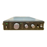
Yaesu FTC-2640 Service Manual (86 pages)
VHF FM Mobile Transceiver
Brand:
Yaesu
| Category:
Transceiver
| Size: 8.98 MB
Table of Contents
Contents
4
VHF Land Mobile Transceiver
6
General Description
6
Performance Specifications
7
General
7
Frequency Range
7
External Connections
7
Semiconductors
8
Ics
8
Fets
8
Transistors
8
Front Panel Controls and Switches
9
Microphone Jack
9
Volume
9
Power
9
Rear Apron Connections
10
Ant
10
Ext Sp
10
Power Cable/Connector
10
Installation
11
Antenna Considerations
11
While Transmitting
11
Typical SWR Test Setup
11
Physical Location of Transceiver
12
Power Connections
12
Power Cord Diagra M
12
Installation Step-By-Step Outline
13
Fmb-4
13
Base Station Installation
14
Power Transformer Primary Connections
14
Theft Guard Installation Using FHR-1
15
Installation Procedure
15
Microphone Connections
16
Operation
17
Technical Notes
18
Circuit Information
19
Parts Designations on Circuit Boards
19
Functions of Circuit Components
19
Circuit Description
22
Receiver
22
Transmitter
22
Automatic Final Protection Circuit
23
Automatic Power Control C Circuit
23
DC Voltage Changeover Circuit
23
PLL Local Signal Oscillator
23
Spurious Suppression at Antenna Jack
24
Spurious Radiation from the Case, Power Cable, Etc.
24
Deviation Circuit
24
Audio Filtering
24
Crystal Data
25
Frequency Relationships
26
Horn Relay Unit
27
AC Power Supply
27
Band Programming
28
Simplex/Duplex Programming
28
Viewed from Solder Side
28
Band Select Jumper Connections
29
Main Board PLL Section
29
Channel Frequency Programming
30
Additional Frequency Programming Examples
36
Band Table
40
Exploded View
42
Servicing
42
Board Layout
43
Top View
43
Bottom View
43
Main Board Part Layout
44
Power Amplifier Board Parts Layout
46
Diode Matrix Board Parts Layout
47
LED Board Parts Layout
48
Relay Board Parts Layout
48
Transistor & IC Pinouts
49
Level Diagram
50
Transmitter Section
50
Receiver Section
51
Voltage Chart
52
Soldering and Desoldering Technique on Printed Circuit Boards
53
Notes on Use of CMOS Components
53
Insertion of Parts on Circuit Boards
53
Basic Soldering Practice
54
Examples of Poor Soldering Practice
54
Soldering to Terminal Posts
54
Fault Localization
55
Typical Part Failures, Causes and Symptoms
55
Maintenance and Servicing
56
Regular Maintenance Plan
56
Performance Checks
56
RX Sensitivity Test Setup
56
Alignment
57
Recommended Alignment Equipment
57
Alignment Frequencies and Matrix Programming Chart
57
PLL Circuit
58
Pll VCV
58
PLL Frequency
58
PLL Level
58
PLL Section Alignment Points
59
Auto Tune
60
Exciter
60
Transmitter Section Alignment Points
61
Power Amplifier
62
APC and AFP
62
Spurious Check with Supply Voltage Variation
63
Modulation and Deviation
63
Receiver Circuits
64
First Local PLL
64
Second Local
64
Sensitivity
64
Squelch
66
Audio Output Distortion and S/N
66
Spurious Response
66
Troubleshooting
67
Parts List
74
Advertisement
Advertisement
Related Products
Yaesu FTC-4625
Yaesu FTC-4610
Yaesu FTC-703A
Yaesu FT-2000 - MENU MODE LIST
Yaesu FT-23R MKII
Yaesu FT-1900E
Yaesu FT-690RII
Yaesu FT-767GX
Yaesu FT-857 HF
Yaesu FTM-200DE
Yaesu Categories
Transceiver
Radio
Receiver
Two-Way Radio
Amplifier
More Yaesu Manuals
Login
Sign In
OR
Sign in with Facebook
Sign in with Google
Upload manual
Upload from disk
Upload from URL