Sign In
Upload
Manuals
Brands
Xylem Manuals
Industrial Equipment
Duron 6
Xylem Duron 6 Manuals
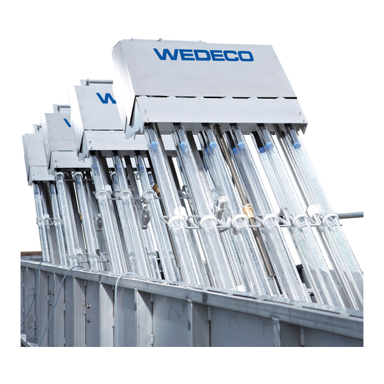
Manuals and User Guides for Xylem Duron 6. We have
1
Xylem Duron 6 manual available for free PDF download: Installation, Operation And Maintenance Manual
Xylem Duron 6 Installation, Operation And Maintenance Manual (128 pages)
Brand:
Xylem
| Category:
Industrial Equipment
| Size: 5 MB
Table of Contents
Table of Contents
3
Introduction and Safety
7
Introduction
7
Safety Terminology and Symbols
7
User Safety
9
Special Hazards
9
UV Exposure
9
Mercury in UV Lamps
10
DI(2-Ethylhexyl)Phthalate (DEHP) and Cadmium (CD) in Cables
10
For USA Only: Labels for FIFRA and California Proposition 65
10
Interference Emission
11
Protecting the Environment
11
End-Of-Life Product Disposal
11
Spare Parts
12
Warranty
12
Transportation and Storage
13
Precautions
13
Examine the Delivery
13
Examine the Package
13
Examine the Unit
14
Lifting Guidelines
14
Lifting
14
Storage Guidelines
14
Long-Term Storage
15
System Description
17
System Overview
17
UV Bank
18
Automatic Wiping System
20
Level Control
21
Low-Level Probe
22
Ultrasonic Level Sensor
22
Downward Opening Penstock
23
Finger Weir
23
Fixed Pipe Weir
24
UV Transmittance Monitor
24
Channel Cover
25
Cabinets
25
ICA Cabinet
26
Electronic Ballast Cabinet
26
Lift Control Cabinet
27
Wiper Control Cabinet
27
Optional Cabinets
28
Mechanical Installation
30
Precautions
30
Necessary Tools and Equipment
31
Requirements
31
Drill Size and Depth
32
Install the Anchor Bolt
33
Drilling: Mounting Plates and Mixing Rods
34
Attach the Drilling Template
35
Drill the Holes for the Mounting Plate and the Mixing Rod
36
Remove the Drilling Template
37
Drilling: Ultrasonic Level Sensor and Low-Level Probe
37
Install the Mounting Plate
37
Install the Mixing Rod
39
Install the Module Guide Rack
40
UV Module Installation
41
Prepare the UV Module
41
Install the UV Module
42
Adjust the Sealing Plate on the UV Module
43
Install the Centering Angle Bracket
44
Adjust the Electric Lift Box
45
Install the UV Light Shield
47
Adjust the UV Light Shield at the UV Module
48
Install the Ultrasonic Level Sensor
49
Adjust the Ultrasonic Level Sensor
49
Install the Low-Level Probe
51
Adjust the Low-Level Probe
52
Installation of Optional Equipment
52
Fixed Weir
52
Downward Opening Penstock
52
Air Compressor
52
UV Transmittance Monitor
52
Electrical Installation
53
Precautions
53
Necessary Tools and Equipment
54
Cabinet Installation
54
Requirements
54
Install the Cabinet
54
Install the Additional Cabinets
55
Install the Wiper Control Cabinet or the Lift Control Cabinet
57
Cable Installation
57
Requirements
57
Install the Cables
58
Maintenance
60
Precautions
60
Inspection
62
Clean the Transparent Surfaces
64
Isolate the UV System
64
Operation of the UV Module Lift
65
Electric Lift Operation
65
Manual Lift Operation
67
UV Module Removal
69
Remove the UV Module: Electric Lift
69
Remove the UV Module: Manual Lift
70
UV Module Installation
71
Install the UV Module: Electric Lift
71
Install the UV Module: Manual Lift
72
Clean the UV Module Manually
72
Replace the UV Lamps
73
Remove the UV Lamp
73
Install the UV Lamp
74
Replace the Wiper Rings
75
Remove the Wiper Rings
75
Install the Wiper Rings
76
Replace the Spindle Nut
77
Remove the Spindle Nut
77
Install the Spindle Nut
80
Replace the UV Sensor
81
Remove the UV Sensor
81
Install the UV Sensor
83
Clean the Filter Mat
84
Water Sampling
85
Precautions
85
Standard
85
Examples of Equipment
85
Sampling Plan
86
Prepare the UV System
87
Sample Collection
88
Collect the Sample: Manually
88
Collect the Sample: Depth Sampler
88
Troubleshooting
89
Precautions
89
Warning
90
AIR CONDITIONER FAILURE, CHANNEL 'X' BANK 'Y
90
Air Compressor Overload
91
Air Pressure Low
91
LAMP FAILURE, CHANNEL 'X' BANK 'Y
91
LAMP HOUR GUARANTEE EXCEEDED, CHANNEL 'X' BANK 'Y
92
LAMP HOUR GUARANTEE EXCEEDED, CHANNEL 'X' BANK 'Y' ROW 1
92
LAMP HOUR GUARANTEE EXCEEDED, CHANNEL 'X' BANK 'Y' ROW 2
93
MODULE LIFT FAILURE, CHANNEL 'X' BANK 'Y
93
SIGNAL FAILURE: INLET PENSTOCK POSITION, CHANNEL 'X
93
SURGE SUPPRESSOR FAILURE, CHANNEL 'X' BANK 'Y
94
Ups Not Ok
94
UV DOSE LOW WARNING, CHANNEL 'X
94
UV INTENSITY LOW WARNING, CHANNEL 'X' BANK 'Y
95
Uv Transmittance below Minimum Design Uvt
96
Uv Transmittance Manual Override Is Enabled
97
WIPE COUNT EXCEEDS WARRANTY, CHANNEL 'X' BANK 'Y
97
WIPE COUNT EXCEEDS WARRANTY, CHANNEL 'X' BANK 'Y' MODULE 1
97
WIPER FAILURE, CHANNEL 'X' BANK 'Y' MODULE 1
97
WIPER NOT at END, CHANNEL 'X' BANK 'Y
98
WIPER NOT at REST, CHANNEL 'X' BANK 'Y
98
Alarm
99
BALLAST INTERMEDIATE VOLTAGE FAILURE, CHANNEL 'X' BANK 'Y
99
BALLAST TEMPERATURE HIGH, CHANNEL 'X' BANK 'Y
100
ECOTOUCH COMMUNICATION FAILURE, CHANNEL 'X' BANK 'Y
100
ENCLOSURE OVERLOAD BREAKER, CHANNEL 'X' BANK 'Y
100
ENCLOSURE TEMPERATURE HIGH, CHANNEL 'X' BANK 'Y
101
FLOW PER LAMP EXCEEDS MAXIMUM VALIDATED LIMIT. RED IS EXTRAPOLATED, CHANNEL 'X
101
Ica 24V Psu #1 Failure
102
Ica 24V Psu #1 Overload
102
Ica Enclosure 24V Psu Failure
103
Ica Enclosure Overload
103
Ica Is on Ups Power
103
Ica Mains Failure
104
INLET PENSTOCK FAILURE, CHANNEL 'X
104
INLET PENSTOCK FAILED to CLOSE, CHANNEL 'X
105
INLET PENSTOCK FAILED to OPEN, CHANNEL 'X
105
INLET PENSTOCK NOT in REMOTE, CHANNEL 'X
105
INLET PENSTOCK OVERLOAD FAILURE, CHANNEL 'X
106
INLET PENSTOCK TORQUE CLOSE, CHANNEL 'X
106
INLET PENSTOCK TORQUE OPEN, CHANNEL 'X
106
I/O BOARD FAILURE, CHANNEL 'X' BANK 'Y
107
LAMP FAILURE, Channel 'X' Bank 'Y' ROW 1
107
MULTIPLE LAMP FAILURE, CHANNEL 'X' BANK 'Y
107
OUTLET PENSTOCK FAILURE, CHANNEL 'X
108
OUTLET PENSTOCK FAILED to CLOSE, CHANNEL 'X
108
OUTLET PENSTOCK FAILED to OPEN, CHANNEL 'X
109
OUTLET PENSTOCK NOT in REMOTE, CHANNEL 'X
109
OUTLET PENSTOCK OVERLOAD FAILURE, CHANNEL 'X
110
OUTLET PENSTOCK POSITION FAILURE, CHANNEL 'X
110
OUTLET PENSTOCK TORQUE CLOSE, CHANNEL 'X
111
OUTLET PENSTOCK TORQUE OPEN, CHANNEL 'X
111
RACK 1 BALLAST OVERLOAD, CHANNEL 'X' BANK 'Y
112
REMOTE IO COMMUNICATIONS FAILURE, CHANNEL 'X
112
SAFETY RELAY FAILURE, CHANNEL 'X' BANK 'Y
113
Scada Communications Failure
113
SIGNAL FAILURE: FLOW RATE, CHANNEL 'X
114
SIGNAL FAILURE: OUTLET PENSTOCK POSITION, CHANNEL 'X
114
SIGNAL FAILURE: ULTRASONIC LEVEL SENSOR 1, CHANNEL 'X
114
SIGNAL FAILURE:ULTRASONIC LEVEL SENSOR 2, CHANNEL 'X
115
SIGNAL FAILURE: UV INTENSITY, CHANNEL 'X' BANK 'Y
115
Signal Failure: Uv System Flow Rate
116
Signal Failure: Uv Transmittance Monitor
116
UV DOSE below MINIMUM DESIGN DOSE, CHANNEL 'X
117
UV INTENSITY LOW ALARM, CHANNEL 'X' BANK 'Y
118
Uv System Flow below Minimum Design Flow
119
Uv System Flow Exceeds Maximum Design Flow
119
Uv Transmittance below Minimum Validated Limit. Red Is Extrapolated
120
Uv Transmittance Monitor Not Ok
120
WATER LEVEL HIGH, CHANNEL 'X
120
WATER LEVEL LOW, CHANNEL 'X
121
WATER LEVEL LOW VIA ULTRASONIC SENSOR, CHANNEL 'X
121
Other Relevant Documentation or Manuals
122
Reference Documents
122
Glossary
123
Terms
123
Advertisement
Advertisement
Related Products
Xylem WEDECO Duron 8
Xylem DREDGEPACK
Xylem WTW DurOx 325
Xylem Ditch Wizard
Xylem Sensus Cordonel DN 65
Xylem Domo M M-Bus
Xylem DIQ/S 281
Xylem Goulds Smart Pump e-SM Drive 111
Xylem Goulds Smart Pump e-SM Drive 303
Xylem Goulds Smart Pump e-SM Drive 315
Xylem Categories
Water Pump
Measuring Instruments
Controller
Industrial Equipment
Accessories
More Xylem Manuals
Login
Sign In
OR
Sign in with Facebook
Sign in with Google
Upload manual
Upload from disk
Upload from URL