Sign In
Upload
Manuals
Brands
XITRON Manuals
Measuring Instruments
XT2640
XITRON XT2640 Manuals
Manuals and User Guides for XITRON XT2640. We have
1
XITRON XT2640 manual available for free PDF download: Operating Manual
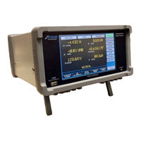
XITRON XT2640 Operating Manual (187 pages)
PRECISION MULTI-CHANNEL HARMONIC POWER ANALYZER
Brand:
XITRON
| Category:
Measuring Instruments
| Size: 3 MB
Table of Contents
Table of Contents
2
About this Manual
7
Warranty Information
8
Product Features
9
Safety
11
Safety Specifications
11
Power and Grounding
11
Terminals and Wiring
11
Environment
11
Inspection
12
Front and Rear Panel Layout
13
Front Panel Layout
13
Rear Panel Layout
13
Getting Started
14
Applications
16
Channels
16
Electrical Channels
16
Mechanical Channel
16
Virtual Power Analyzers (or Vpa)
16
Typical Single Vpa Applications
17
Typical Dual Vpa Applications
18
Typical Triple Vpa Applications
19
Mechanical (Motor/Generator) Applications
19
Wiring to Channels
20
Ø Wiring Using Internal Current Measurement
20
Ø Wiring Using External Current Measurement
21
Ø Wiring Using 280X Iec Adaptor Cord
22
Ø 3 W or 3 Ø 3 W (2 Ch ) Wiring Using Internal Current Measurement
23
Ø 3 W or 3 Ø 3 W (2 Ch ) Wiring Using External Current Measurement
24
Ch ) or 3 Ø 4 W Wiring Using Internal Current Measurement
25
Ch ) or 3 Ø 4 W Wiring Using External Current Measurement
26
Mechanical (Motor) Measurement Wiring
26
Mechanical Speed and Direction Inputs
27
Mechanical Torque Inputs
27
Powering the Xt2640
28
Turning Power On
28
Turning Power off
28
Measurement Result Terminology
29
Wiring Phase Indications
29
Leading/Lagging Determination
29
Peak and Valley Results
29
Individual Channel Results
29
Individual Vpa Total Results
30
Voltage Results
30
Wye Voltage Result
30
Delta Voltage Result
30
Current Results
30
Watts Results
30
VAR and VA Results
30
Power Factor Results
30
Inrush Results
30
Phase Results
30
Non-Harmonic Phase Results
31
Harmonic Phase Results
31
Relative Individual Harmonics Results
31
Percentage Distortion Results
31
Thc, Pohc and Pwhc Results
31
Mechanical (Motor) Results
31
Using the Xt2640 from an Interface
31
Operating from the Front Panel
32
Touch Panel
32
Buttons
32
Main Screen Layout
32
Main Screen Select Buttons
32
July
32
Remote Button
33
Power Button
33
Data Area
33
Error Info Area
33
Holding or Releasing Measurements
33
Integration Info Area
34
USB Drive Info Area
34
Interface Info Area
34
Time and Date Info Area
34
System Configuration and Viewing Build Information - the Sys Config Screen
34
Setting Power and Measurement User Preferences
35
Configuring the Interface
37
Setting the Clock and Time/Date Formats
39
Upgrading the XT2640 Option Content
39
Configuring Measurements - the Meas Config Screen
39
Selecting the Overall Measurement Mode
39
Configuring a VPA
40
Configuring Mechanical Measurements (Motor or Generator)
44
Importing, Exporting or Recording the Measurement Configuration
46
Viewing Numerical Measurements - the Power Data Screen
47
Viewing Measurement Results for an Individual Channel
47
Viewing Measurement Results for a VPA
49
Viewing Efficiency and Power Loss Measurement Results
51
Viewing Mechanical Measurement Results
52
Exporting Or Recording Measurements
52
Viewing Custom Numerical Measurements - the Custom Data Screen
53
Viewing Harmonics Measurements - the Harmonics Screen
53
Using the Numerical Listing
54
Comparing Harmonics against Limits
55
Exporting or Recording Harmonics
55
Viewing Fundamental Signal Vectors - the Vectors Screen
56
Recording Vectors
56
Graphically Viewing Past Measurements - the History Screen
57
Selecting and Configuring the Traces to Show
57
Changing the Way in Which Time Is Displayed on the Chart
58
Starting, Stopping, and Restarting the Chart
58
Prohibiting Data Collection Temporarily
58
Using the Cursor and Zooming the Chart
58
Rescaling the Chart Traces
59
Exporting or Recording History
59
Historical Data Availability
60
Screens
61
Viewing Periodic Waveforms - the CYCLE VIEW Screen
61
The Scope S Creens
61
An Oscilloscope - the SCOPE VIEW Screen
63
Performing En50564 Low Power Measurements - the Stby Power Screen
67
Performing En61000-3-2
67
Screen
67
Performing and Viewing a Spectrum Analysis - the Spectrum Screen
67
Configuring Spectrum Analysis
67
Optimising Configuration for Spectrum Measurements
67
Holding Measurements While Performing Spectrum Analysis
68
Viewing Spectrum Analysis Results
68
Exporting or Recording SPECTRUM Data
68
Optimizing Low-Level DC Performance
70
Nternal DC Ero Djustment
70
External DC Zero Adjustment
70
Using an X Current Option Input at Low Levels
70
Performing Startup or Inrush Measurements
71
Obtaining a Graphical and Numerical Inrush Current Measurement
71
Obtaining a Numerical Inrush Current Measurement
73
Recording Inrush Data
74
Integrating Data
75
Configuring Integration
75
Selecting to Perform Manually Timed Integration
75
Selecting to Perform an Automatically Timed Integration
75
Starting and Stopping Integration
76
Exporting or Recording Integrated Measurements
76
Performing Measurements of Pwm Generated Signals
78
Choice of Channels
78
Wiring Recommendations
78
Recommended 3-Phase, 3-Wire Wiring Method Selection
78
Configuration Recommendations
79
Recommended FREQ SPEED System Preference
79
Recommended MEAS CONFIG Settings
79
PWM Generator Efficiency Measurements
80
Performing En50564 Low Power Measurements
82
VPA Measurement Configuration for EN50564:2011 Measurements
82
Low Power Measurement Configuration
83
Performing a Low Power Measurement and Viewing the Results
85
Recording STBY POWER Data
86
Testing Compliance to Harmonics Emissions Standards
87
Standards Compliance
87
Relevant Standards
87
Supply, XT2640 and EUT Wiring
88
Repeatability Requirements
89
EUT Classifications and Limits Selection
89
Range of XT2640 Measurements for Compliance
90
Compliance Tests Performed by the XT2640 During Assessment
92
Measurements
93
Xt2640 for En61000‐3‐2 or ‐12 M Easurements
93
Using the Other Results Screens
94
Using the HARMONICS Screen
94
Performing an Assessment of Aeut
94
Selecting the Channel to View Results
94
Selecting How the Limits Reference(S) Are Obtained
95
Configuring and Starting an Assessment
95
Viewing the Results of an Assessment
97
Changing the Configuration and Reassessing the EUT
100
Continuing a Paused Assessment
100
Stopping an Assessment
100
Recording the Results of an Assessment
100
Measuring Electrical Power to Avionics Requirements
106
Connecting the Xt2640
106
Configuring the Measurements Made by the Xt2640
106
AC 3-Phase Supplies
106
AC 1-Phase Supplies
107
DC Supplies
108
Using the Xt2640 to Monitor the Supply
108
Confirming the Voltage and Frequency of the Supply
108
Confirming the Voltage Modulation Depth of the Supply
108
Confirming the DC Voltage Content of the Supply
109
Confirming the Voltage Distortion of the Supply
109
Confirming the Voltage Ripple Content of the Supply
109
Using the Xt2640 to Test Compliance to Loading Requirements
109
Testing the Load Current Distortion Meets Requirements
110
Testing the Load Phase Imbalance Meets Requirements
110
Testing the Load DC Current Content Meets Requirements
110
Testing the Load Inrush Current Meets Requirements
110
Testing the Load Current Modulation Meets Requirements
111
Testing the Load Power Factor Meets Requirements
111
Sharing Measurements and Activities Within Multiple Instruments
112
Interconnecting Multiple Xt2640S
112
Interconnecting Not Using the LAN Interface with a Computer
112
Interconnecting While also Using the Lan Interfaces with Acomputer
112
Having Several Groups of Xt2640S Within a Single Network
112
Configuring Multi-Unit Capability
112
Synchronizing Measurements Within a Group of Units
113
Holding and Releasing Measurements in a Group of Units
113
Starting , Stopping and Configuring Integration in a G
113
Units
113
Starting and Stopping Historical Data Collection in a Group of Units
113
In, MID and out Total Power and Efficency Data in a Group of Units
114
Synchronizing Measurements between Vpas
115
Using a Usb Drive
117
Drive Compatibility
117
Checking Drive Compatibility
117
Files
118
Checking the Drive File Structure
118
Exporting Files to a Drive
118
Screen Image File (.BMP Extension)
119
Binary (.CFG Extension) Files
119
Comma Separated Value (.CSV Extension) Files
119
Importing Files from a Drive
122
Importing Binary Configuration, Custom Screen and Harmonic Limits Files
122
Creating and Importing an ASCII Harmonics Limits File
123
Creating and Importing an ASCII Custom Screen Definition File
123
Updating the Firmware or the FPGA
125
Changing the Welcoming Screen
125
Data Logging
125
Configuring the Data Log
126
Configuring Data Logging Timing
127
Configuring Data Logging Record Contents
127
Starting and Stopping Data Logging
128
Clearing the Data from a Completed Unsaved Data Log
128
Viewing Data Logging Status
128
Exporting a Data Log from the Internal Memory
129
Internal Buffer Usage
129
Optimizing and Testing File Write Speed
129
Computer Control of the Xt2640
131
RS232 (Serial) Interface
131
Using the Xt2640 from an Interface 1
131
LAN (Ethernet) Interface
132
USB Interface
134
GPIB Interface
137
Command Syntax
138
Special Characters
138
Fields Within a Command
139
Responses to Commands
140
Response Fields
140
Command Keywords and Fields
141
Interface Clear Commands
141
Local/Remote State Control Commands
141
Error Register Query Commands
141
Unit and Channel Identification Query Commands
142
GPIB Specific Commands
142
Date and Time Control and Query Commands
143
System Preferences Set and Query Commands
143
Measurement State Control and Query Commands
144
Measurement Configuration Edit Commands
145
Measurement Configuration Query Commands
149
Configuration Save and Load Commands
151
Harmonics Limits Configuration and Configuration Query Commands
152
DC Zero Control and Query Commands
152
Custom Screen Configuration and Configuration Query Commands
152
Measurement Results Query Commands
153
Rdef Measurement Definition Field Sub-Fields
154
Ddef Measurement Definition Field Sub-Fields
157
Inside the Xt2640
160
General Measurement Methods
160
Channel Circuitry
161
Sampling Control
161
Channel Measurements
161
Vpa Measurements
162
VPA Fundamental Frequency
162
VPA Amplitude Measurements
162
Data Collection
162
Integrated Data
163
Data Logging
163
Options and Accessories
164
Option H500
164
Option en
164
Accessory Rm-7
164
Accessory 280X Iec Adaptor Cord
164
Accessory Hc-7
164
Dimensional, Environmental and Power Supply Specifications
165
Dimensional
165
Environmental
165
Power Supply
165
Electrical Channel Input and Accuracy Specifications
166
Input Isolation Specifications
166
Voltage Measurement Specifications
166
Voltage Input Capability and Characteristics
166
Voltage Measurement Accuracy
167
Current Measurement Specifications
169
Current Input Capability and Characteristics
169
Current Measurement Accuracy
170
Watts, Var And Va Measurement Specifications
174
Watts, VAR and VA Measurement Specifications
176
Power Factor Measurement Specifications
178
PF Measurement Accuracy Table
178
Frequency Measurement Specifications
179
Mechanical Channel Input and Accuracy Specifications (Mt Type)
180
Nput Apabilities and Haracteristics
180
Digital Input Measurement Specifications
180
Analog Input Measurement Specifications
180
C Haracteristics
180
Analysis Specifications
181
Integration Specifications
181
Harmonic Analysis Specifications
181
Spectrum Analysis Specifications
181
Cycle View Specifications
182
Scope Specifications
182
Historical Data Collection Specifications
182
Data Logging Specifications
182
Calibration Adjustment
183
Equipment Required
183
Adjustment Procedure
184
Starting the Interface to the XT2640
184
Adjusting each Channel in the XT2640
184
Finishing the Procedure
186
Calibration Verification
187
Advertisement
Advertisement
Related Products
XITRON Categories
Printer
Remote Starter
PCI Card
Measuring Instruments
More XITRON Manuals
Login
Sign In
OR
Sign in with Facebook
Sign in with Google
Upload manual
Upload from disk
Upload from URL