Sign In
Upload
Manuals
Brands
Woodward Manuals
Control Unit
8406-121
Woodward 8406-121 Control Package Manuals
Manuals and User Guides for Woodward 8406-121 Control Package. We have
1
Woodward 8406-121 Control Package manual available for free PDF download: Installation And Operation Manual
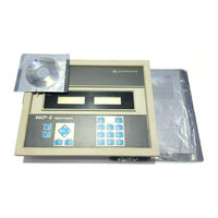
Woodward 8406-121 Installation And Operation Manual (234 pages)
Engine Generator Control Package
Brand:
Woodward
| Category:
Control Unit
| Size: 3 MB
Table of Contents
Table of Contents
3
Warnings and Notices
9
Battery Charging
10
Electrostatic Discharge Awareness
10
Chapter 1. General Information
11
Introduction
11
Regulatory Compliance
11
Control Electrical Ratings
11
Technical Specifications
11
Chapter 2. Control Overview
12
Introduction
12
Hardware
14
Environmental Specification
14
Physical Specification
14
Accessories
14
Figure 2-1. Physical Outline with Dimensions of EGCP-2
15
Figure 2-2. EGCP-2 Interface Connections
16
Operator Interface
17
Figure 2-3. Operator Interface
17
Navigation Procedure
22
Figure 2-4A. EGCP-2 Navigation (1)
22
Figure 2-4B. EGCP-2 Navigation (2)
23
Figure 2-4C. EGCP-2 Navigation (3)
24
Figure 2-4D. EGCP-2 Navigation (4)
25
Figure 2-4E. EGCP-2 Navigation (5)
26
Chapter 3. Electrical Installation and Specifications
27
Electrical Connections
27
Figure 3-1. Cageclamp Termination Blocks (Example Photos)
27
Figure 3-2. Recommended Single Point Grounding Scheme
28
Figure 3-3. Wiring Diagram for EGCP-2
30
Input Power
31
Figure 3-4. Dip Switch Locations
31
Potential Transformer (PT) Inputs
32
Figure 3-5. Three Wire Delta PT Connections for EGCP-2
33
Figure 3-6. Four Wire Wye PT Connections
33
Figure 3-7. Utility/Local Bus Single PT Wiring for Delta and Wye Configuration for
34
Figure 3-8. Utility/Local Bus Single PT Wiring for Delta and Wye Configuration for Multiple or Single Engine Prime Power Applications
35
Figure 3-9A. PT Wiring Relationships for Generator, Bus, and Utility Inputs
36
Figure 3-10A. PT Wiring Relationships for Generator, Bus, and Utility Inputs
38
Figure 3-10B. PT Wiring Relationships for Generator, Bus, and Utility Inputs
39
Current Transformer (CT) Inputs
40
Figure 3-11. Current Transfer Wiring Diagram for EGCP-2
40
MPU (Speed) Input
41
Figure 3-12. Wiring Diagram for MPU Input
41
Process Import/Export Input
42
Figure 3-13A. Wiring Diagram for Process Import/Export Input
42
Figure 3-13B. Connecting a Kw Transducer Signal to Multiple EGCP-2S
42
Coolant Temperature and Oil Pressure Inputs
43
Figure 3-14. Wiring Diagram for Pressure Inputs
43
Figure 3-15. Wiring Diagram for Temperature Inputs
44
Speed Bias and Voltage Bias Outputs
46
Figure 3-16. Wiring Diagram for Speed Bias and Voltage Bias Outputs
47
Discrete Inputs
48
Relay Outputs
49
Figure 3-17. Wiring Diagram for Typical Discrete I/O Connections
49
Figure 3-18. Example of the Mains Breaker no Output Connected to Close the Mains (Utility) Breaker (ENERGIZE to CLOSE)
50
Figure 3-19. Example Using the NC Output to Control the Mains (Utility) Contactor (ENERGIZE to OPEN)
51
Figure 3-20. Example of the Generator Breaker Close no Output Connected to Close the Generator Breaker (ENERGIZE to CLOSE)
52
Figure 3-21. Example Using the no Contacts to Control the Generator's Contactor (ENERGIZE to CLOSE)
52
Figure 3-22. Example Using the no Contacts to Control the Mains Breaker Trip (Open) Coil (ENERGIZE to OPEN)
55
Figure 3-23. Example Using the NC Contacts to Control the Generator Breakers Open Coil (DE-ENERGIZE to OPEN)
56
Figure 3-24. Generator Breaker and Contactor Close and Open Logic
56
AC Inputs
58
DC Inputs and Outputs
58
Discrete Inputs
59
Discrete Outputs
59
Communication Ports: RS-485 & RS-422 (1 Each)
60
Hardware Connections
60
Figure 3-25. RS-422 Communications
61
Inter-Control Communications (RS-485 Network)
62
Figure 3-26. RS-485 and RS-422 Termination Diagrams
62
Alarms and Shutdowns
63
Figure 3-27. RS-485 Inter-Control Communications
63
Chapter 4. Software Overview
66
Introduction
66
Status Screens
66
Figure 4-1. System Overview Engine off Line
66
Figure 4-2. System Status Screen-Isochronous
68
Figure 4-3. System Status Screen-Baseload
68
Figure 4-4. Engine Status
69
Figure 4-5. Generator Status (Voltage Line to Neutral)
70
Figure 4-6. I/O Status
71
Figure 4-7. Synchronizer Status
72
Figure 4-8. Kw Load Status
73
Figure 4-9. PF /Kvar Status
74
Figure 4-10. Sequencing Menu
75
Figure 4-11. Sequencing Menu (Multi-Unit)
76
Figure 4-12. ATS (Automatic Transfer Switch) Status
77
Security Access
78
Figure 4-13. Security Code Display
78
Alarm / Event Log
79
Figure 4-14. Alarm / Event Screen
79
Figure 4-15. Empty Event Log
80
Configuration Menus
81
Figure 4-16A. Configuration Menu List (Screen 1)
81
Figure 4-16B. Configuration Menu List (Screen 2)
81
Figure 4-16C. Configuration Menu List (Screen 3)
82
Figure 4-17. Program Configuration Error
83
Figure 4-18. AC Power Triangle
86
Figure 4-19. Breaker Logic and Contactor Logic
89
Shutdowns and Alarms
90
Figure 4-20. Generator High/Low Voltage Alarms
90
Figure 4-21. Generator Over/Under Frequency
91
Figure 4-22. Delay Time Is 10 Seconds, Current Goes to 190 A, an Alarm or Shutdown will be Received in 30 Seconds
93
Figure 4-23. Delay Time Is 10 Seconds, Current Goes to 200 A, an Alarm or Shutdown will be Received in 15 Seconds
93
Figure 4-24. Delay Time Is 10 Seconds, Current Goes to 220 A, an Alarm or Shutdown will be Received in 7.5 Seconds
94
Figure 4-25. Reverse Power
95
Engine Control
96
Synchronizer
98
Figure 4-26. Typical Circuit Using Permissive Function and Run for Auto/Manual Synchronizing
98
Figure 4-27. Voltage Matching (1% Set Point)
99
Figure 4-28. Maximum Phase Window = 10 Degrees
100
Real Load Control
101
Reactive Load Control
104
Process Control
105
Figure 4-29. EGCP-2 Control Dip Switch
105
Figure 4-30. Direct (Export) Process Action
106
Figure 4-31. Indirect (Import Power) Process Action
106
Figure 4-32. Direct (Import/Export) Process Action
106
Transfer Switch
110
Sequencing and Comms (Communications)
112
Calibration Menu
114
Figure 4-33. Process in Scale
115
Figure 4-34. Measured Vs. Monitored
115
Figure 4-35. Typical AVR with Aux Input (Newage SX-440)
117
Figure 4-36. Typical AVR with External Voltage Adjust Potentiometer
117
Figure 4-37. AVR Droop
118
Figure 4-38. Oil Pressure Sensor Curve
122
Figure 4-39. Water Temperature Curves
125
Figure 4-40. EGCP-2 Water Temperature Characteristics
125
Chapter 5. Control Features and Functions
127
Engine Control
127
Engine Protection
127
Generator Voltage and Reactive Load Control
127
Generator Protection
127
Mains Sensing
128
Synchronizing
128
Load Control
128
Sequencing
128
Engine Cranking
129
Idle/Rated Relay Output
130
Generator Voltage Control
130
Generator Load Control
131
Figure 5-1. Droop Mode
132
Figure 5-2. Isochronous Mode
133
Figure 5-3. Droop/Isochronous Load Sharing
134
Automatic Generator Loading Functions
135
Synchronizer Description
138
Figure 5-4. Synchronizer Time Line-Standard Sequence
142
Figure 5-5. Loss of Mains Detection Active
143
Figure 5-6. Generator off Line
143
Figure 5-7. Mains Parallel Unit with Voltage/Frequency Detect
144
Figure 5-8. Mains Parallel Unit(S) with Load Surge Detect
144
Generator Sequencing
145
Figure 5-9. Typical Automatic Sequencing Scenario
146
Figure 5-10. Original System Configuration
149
Figure 5-11. after a Change of Priority-Units Not Operating
149
Figure 5-12. Original System Configuration
150
Figure 5-13. Master Transfers to Unit 2
150
Figure 5-14. Changing the Priority of a Slave Unit
152
Figure 5-15. Changing the Priority of a Slave Unit
152
Figure 5-16. Changing the Priority of a Slave Unit
153
Figure 5-17. Changing the Priority of a Slave Unit
153
Figure 5-18. Changing the Priority of a Slave Unit
154
Figure 5-19. Changing the Priority of a Slave Unit
154
Chapter 6. Calibration of Control Inputs and Outputs
156
Introduction
156
Calibration of Generator Pts and Cts
157
Calibration of the Bus PT
161
Speed Bias Output
162
Voltage Bias Output
162
Figure 6-1. Relationship between Voltage Bias and Generator Voltage
163
Chapter 7. General Start-Up Instructions
164
Before Starting the Generator Set
164
Sequence of Start-Up and Checking Parameters
165
Loading the Generator Set
165
Chapter 8. Troubleshooting
168
Control Hardware and I/O
168
Engine Control/Sensing Parameters
169
Synchronization
170
Breaker Close/Open Control
171
Real Load Control
172
Reactive Load Control
173
Sequencing
174
Mains/Bus Sensing
175
Communications
175
Chapter 9. Definition of Terms
176
Chapter 10. Service Options
182
Product Service Options
182
Woodward Factory Servicing Options
183
Returning Equipment for Repair
183
Replacement Parts
184
Engineering Services
184
How to Contact Woodward
185
Technical Assistance
185
Appendix A. Connector Information
186
Appendix B. Speed Bias Connections
188
Speed Control
188
Appendix C. Voltage Bias Connections
193
Basler AVC63-12
193
Basler AEC63-7
194
Basler APR63-5
195
Basler APR63-5 with AMP200
196
Basler KR2F, 4F, or 7F
197
Basler DECS 15
198
Basler DECS 100
199
Basler DECS 200
200
Basler SR4A or SR8A
201
Basler SSR
202
Caterpillar CDVR
203
Caterpillar Digital Voltage Regulator
204
Caterpillar VR3
205
Caterpillar VR6
206
KATO KCR360 or 760
207
KATO K65-12B or K125-10B
208
Leroy Somer R438, R448, or R449
209
Leroy Somer R600
210
Leroy Somer R610
211
Marathon PM 100/200
212
Marathon 2000E
213
Mecc Alte UVR
214
Newage MA325
215
Newage MA327
216
Newage MX321/341
217
Appendix D. EGCP-2 Set Point Worksheet
218
Configuration Menu
218
Shutdown and Alarms Menu
219
Engine Control Menu
222
Synchronizer Menu
224
Real Load Control Menu
225
Reactive Load Control Menu
226
Process Control Menu
227
Transfer Switch Menu
228
Sequencing and Comms Menu
229
Calibration Menu
230
Declarations
232
Egcp-2 Control Specifications
233
Advertisement
Advertisement
Related Products
Woodward 8406-120
Woodward Flo-Tech 8400-511
Woodward 8440-1816
Woodward 8440-1817
Woodward 8440-1818
Woodward 8440-1831
Woodward 8440-1037
Woodward 8440-1015
Woodward 8440-2250
Woodward 8440-2252
Woodward Categories
Controller
Control Unit
Relays
Control Systems
Industrial Equipment
More Woodward Manuals
Login
Sign In
OR
Sign in with Facebook
Sign in with Google
Upload manual
Upload from disk
Upload from URL