Sign In
Upload
Manuals
Brands
Wexxar Manuals
Industrial Equipment
WF30T
Wexxar WF30T Manuals
Manuals and User Guides for Wexxar WF30T. We have
1
Wexxar WF30T manual available for free PDF download: Operation And Service Manual
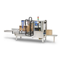
Wexxar WF30T Operation And Service Manual (190 pages)
Case Former
Brand:
Wexxar
| Category:
Industrial Equipment
| Size: 9 MB
Table of Contents
Table of Contents
3
List of Tables
6
Preface
11
About this Manual
12
How to Use this Manual
13
1 Safety
14
Safety Considerations
15
Safety Standards
15
General Precautions
15
Lock-Out Compliance
16
Compressed Air
16
Electrical Power
16
Conveyor Drivebelts
16
Guard Doors
16
Figure 1-2: Safety Guard Doors
16
Safety Interlocks
17
Cautionary Labels
17
Touchscreen Cautionary Alerts
17
Lubricants, Etc
17
Figure 1-3: Examples of Safety Interlocks
17
2 Installation
18
Prerequisites
18
Site Environment Consideration
18
Removal from Crate
19
Mechanical Assembly
19
Location, Leveling and Conveyors
20
Location
20
Leveling
20
Discharge Conveyor
21
Service Connections
21
Compressed Air
21
Electrical Power
22
Figure 2-1: Main Disconnect Switch
22
3 Component Identification
23
Figure 3-2: Operator's Side View
24
Figure 3-3: Left Hand (Infeed) View
24
Major Components (Alphabetized)
25
Pin and Dome Technology
29
4 Theory of Operation
30
Sequence of Operations
30
Sensors
32
Optical Proximity Sensors
32
Inductive Sensors
32
Sensor Cables
32
Table 1: Optical Proximity Sensors
32
Table 2: Inductive Sensors
32
Table 3: Sensor Cables
32
Remote Demand Sensor
33
Magazine Management
33
Interlock Switches
33
Table 4: Remote Demand Sensor
33
Table 5: Magazine Management Sensors
33
Table 6: Interlock Switches
33
Tape Management System
34
Table 7: Tape Management System Sensors
34
Sensor Locations
35
Pneumatic Valve Operation
37
Solenoid Valves
37
Servo Valves
37
Factors Influencing Pneumatic Speeds
38
Non-Lube Pneumatic System
38
Low Pressure Switch
39
5 Controls
40
Controls Overview
40
Controls Description
40
Figure 5-1: 'MAIN DISCONNECT' Switch
40
Figure 5-3: 'EMERGENCY STOP' Button
40
Figure 5-5: 'Service' Screen
41
Figure 5-6: 'MAIN CONTROL' Button
41
Figure 5-7: 'Main Control' Screen
42
Figure 5-8: 'START' Button
42
Figure 5-10: 'Touch-Sensitive Displays
43
Figure 5-11: 'Case Dimension' Buttons
43
Figure 5-12: 'Box Settings' Screen
43
Table 8: Case Measurement Dimensions
44
Figure 5-14: 'SELECTED CPM and CPM RANGE' Status Indicators
44
Figure 5-15: 'JOG CONTROL' Button
44
Figure 5-16: 'Jog Control' Screen
45
Figure 5-17: Blinking Sensor 'LS6
45
Figure 5-19: 'MACHINE CYCLE JOG' Button
46
Figure 5-20: 'SETUP' Button
46
Figure 5-21: 'Setup' Screen
46
Figure 5-22: 'DRY CYCLE ON' Toggle Switch
47
Figure 5-23: 'DRY CYCLE ACTIVE' Indicator
47
Figure 5-24: 'Remote Demand' Switch on
47
Figure 5-25: 'Dry Cycle' Switch on
47
Figure 5-26: 'REMOTE DEMAND ON' Toggle Switch
47
Figure 5-27: 'REMOTE DEMAND ON' Indicator
47
Figure 5-31: 'MACHINE FEEDBACK' Button
48
Figure 5-32: 'Machine Feedback' Screen
48
Figure 5-34: 'Troubleshooting' Screen
49
Figure 5-35: 'PLC INPUTS' Button
49
Figure 5-36: PLC Inputs Screen
50
Figure 5-37: Illuminated 'PLC INPUTS' Status Indicator
50
Figure 5-38: Sample Alarm Diagnostic Detail Screen
50
Figure 5-39: 'PLC OUTPUTS' Button
51
Figure 5-40: 'PLC Outputs' Screen
51
Figure 5-41: Illuminated 'PLC OUTPUT STATUS' Indicator
52
Figure 5-43: 'SETUP GUIDE/HELP' Screen
52
Figure 5-44: Setup Guide Detail Screen Button
53
Figure 5-45: Sample Setup Guide Detail Screen
53
Figure 5-46: 'BACK' and 'FORWARD' Buttons
53
Figure 5-47: 'PARAMETERS' Button
53
Figure 5-48: 'PARAMETERS' Screen
54
Figure 5-50: 'HOMING VALUE' Button
55
Figure 5-51: 'Current Value' Display
55
Figure 5-52: 'INITIAL SPEED' Button
55
Figure 5-53: 'RAMP RATE' Button
56
Figure 5-54: 'HOMING VALUE' Button
56
Figure 5-55: 'Current Value' Display
56
Figure 5-56: 'INITIAL SPEED' Button
56
Figure 5-58: 'ACTUAL CPM' Button
57
Figure 5-59: 'CYCLE MODE' Button
57
Figure 5-62: 'STOP' Button
57
Figure 5-63: 'DRY CYCLE OFF' Button
57
High Speed Servo Settings
58
Low Speed Servo Settings
58
Table 9: High Speed Servo Settings
58
Table 10: Low Speed Servo Settings
58
Figure 5-64: 'DRY CYCLE ON' Button
58
Figure 5-65: 'PREVIOUS' Button
58
6 Operating Procedures
59
Safety
59
Start-Up
60
Preliminary Checks
60
Start-Up Procedures
61
Table 11: Preliminary Start-Up Checklist
61
Table 12: Mechanism HOME Positions and Valve Numbers
61
Table 13: Machine Start-Up Procedures
62
CYCLE' Operation
63
JOG' Operation
63
Monitoring
63
Monitoring Machine Operation
63
Loading the Magazine
64
Clearing a Case Jam
65
Shutdown
67
Table 16: Machine Shutdown
67
7 Case Size Adjustments
68
Safety
68
Table 17: Case Size Range
69
Figure 7-1: Dimensions on Left and Right Hand Cases
69
Figure 7-2: Case Measuring Scale
69
Figure 7-3: Mast Assembly Components
70
Flat Case Height (Dimension 'B')
71
Table 18: Dimension 'B' Adjustments
72
Figure 7-6: Adjusting the Collar Assembly
72
Formed Case Height (Dimension 'E')
73
Figure 7-7: Dimension 'E
73
Figure 7-8: Head-Up Latch
73
Table 19: Dimension 'E' Adjustments
74
Figure 7-10: Forming Head - OPEN and down
74
Case Width (Dimension 'D')
75
Table 20: Dimension 'D' Adjustments
76
Figure 7-13: 'D1' Adjustments
76
Figure 7-14: 'D2' Adjustments
76
Case Length (Dimension 'C')
77
Figure 7-15: Dimension 'C
77
Figure 7-16: Main Magazine Assembly Components
77
Table 21: Dimension 'C' Adjustments
78
Figure 7-18: Case in the Forming Area
78
Flat Case Width (Dimension 'A')
79
Figure 7-19: Dimension 'A
79
Figure 7-20: Dimension 'A' Locking Handles
79
Feedbelt Horizontal Adjustments (Dimension 'H')
80
Table 23: Dimension 'H' Adjustments
80
Figure 7-21: Red Clamp Handles
80
Figure 7-22: Feedbelt Positions
80
Case Separator Horizontal Adjustment (Dimension 'G')
81
Corrugate Thickness Adjustment (Dimension 'F')
81
Table 24: Dimension 'G' Adjustment
81
Figure 7-23: Case Separator Adjustment Handles
81
Figure 7-24: Case Separator Adjustment Handles
81
Jawplate 'F' Adjustment
82
Caliper 'F' Adjustment
83
Figure 7-27: Caliper Adjustment
83
Table 25: Dimension 'F' Adjustments
84
8 Other Machine Adjustments
85
Safety
85
Stabilizer Bars and Pinblocks
86
Figure 8-1: Pinblock Orientation
86
Figure 8-2: Jawplate Assembly
86
Magazine
87
Table 26: Magazine Pusher Adjustment
87
Figure 8-3: Magazine Pusher
87
Sensor Ls-7 Adjustment
88
Minor Flap Folders
88
Testing the Size Adjustments
88
Figure 8-4: Flap Folders
88
Table 27: Mechanism HOME Positions
89
Table 28: Full Cycle Sequence
89
Figure 5-33: 'TROUBLESHOOTING
89
Quick Size Change Guide
90
Table 29: Sensor Adjustment References
90
Table 30: Dimension Adjustment Reference
91
Figure 8-5: Minor Flap Folder Top Plates
91
9 Machine Maintenance
92
Safety
92
Maintenance
93
Inspections
93
Table 31: Machine Inspection
93
Cleaning
94
Table 32: Cleaning the Machine
94
Preventative Maintenance Schedule
95
Typical Maintenance Adjustments
96
Machine Output Rate
96
Mechanism Speeds
96
Magazine Pusher
97
Magazine Feedbelts
97
Injector Assembly
98
Mast Assembly
98
Forming Head
99
Discharge Pusher
99
Shock Absorbers
99
Conveyor Belt Tension & Tracking
100
Figure 9-1: Conveyor Belt Tensioning
100
Discharge Conveyor Assemblies
101
Machine Management System
101
Tape Head Adjustments
101
Proximity Sensors
102
Flap Folder Assemblies
102
Figure 9-2: Inductive Sensor Adjustment Range
102
Pneumatic System Maintenance
103
Pneumatic Supply Adjustments
103
Valve Bank
103
Filter-Regulator
103
General Pneumatics
104
Electrical System Maintenance
104
Safety Circuit
104
Electrical Enclosure
104
Mechanical Maintenance
105
Vertical Alignment Procedures
105
Maintenance Parts List
106
Wear Parts
106
Lubrication
106
Moving Components
106
Ball Bearings
106
Sealed Guide Wheels
106
Figure 9-3: Mast Assembly Showing Guide Wheels
106
Table 47: Lubricants
107
Figure 9-4: Discharge Pusher Sealed Guide Wheels
107
Figure 9-5: Mast Assembly Sealed Guide Wheels
107
10 Troubleshooting & Repairs
108
Safety
108
General Troubleshooting
109
Table 48: General Troubleshooting Reference
110
Machine Sequence Troubleshooting
112
Table 49: Machine Sequence Troubleshooting
112
Table 50: Error Codes
113
Electrical Troubleshooting
114
Tape Applicator Troubleshooting
116
Pneumatic Troubleshooting
116
Table 51: General Pneumatic Troubleshooting
116
Table 52: Forming Head too Slow; Jaw Speed Normal
116
Table 53: both Forming Head and Jaw too Slow
117
Table 54: Jaw too Slow; Forming Head Speed Normal
118
Table 55: Forming Head Not Moving
118
Other Typical Pneumatic Issues
119
Table 56: Jaw Not Moving
119
Led Status Tables
120
Table 57: PLC Input LED Status Table for Jog Step Sequence
120
Table 58: PLC Output LED Status Table for Jog Step Sequence
121
Repair Procedures
122
Pneumatic Cylinder Repairs
122
Magazine Repairs
123
Forming Head Bearing Repairs
123
Major Flap Folder Repairs
123
Solenoid Valve Repairs
124
Conveyor Drivebelt Repairs
124
Drivebelt Bearings Repairs
124
Gearmotor Repairs
124
11 Engineering Specifications
125
Operating Parameters
125
Machinery Drawings
125
Program Code
125
Table 59: Operating Parameters
125
12 Training Guide
126
Instructor Data Sheet
126
Training Outlines
127
Table 60: Training Outlines
127
Performance Checklists
129
Table 14: Machine Loading Checklist
129
Table 15: Clearing Jams
129
Table 22: Dimension 'A' Adjustments
129
Table 33: Magazine Pusher Maintenance
129
Table 34: Feedbelt Maintenance
129
Table 35: Injector Maintenance
129
Table 36: Mast Maintenance
129
Table 37: Forming Head Maintenance
129
Table 38: Discharge Pusher Maintenance
129
13 Service & Warranty
131
14 Options
132
Machine Management System
132
Tape Monitoring
132
Magazine Monitoring
132
Normal Operation
133
Figure 14-1: Beacon Lamp Status Indicators
133
Index
134
Appendix A
137
Material Safety Data Sheets: Fuchs Lubricants - Geralyn FMG 387
137
Appendix B
145
Material Safety Data Sheets: Keystone Lubricants - Nevastane HT-2
145
T Cable Ofcontents
153
Installing the Bel 290
154
Leveling the Machine
154
Installing the Tape Heads
155
Power Connections
155
Electric
155
Compressed Air
155
Machine Adjustments
156
Case Height Adjustment
157
Case Dimension 'E' Adjustment
157
Case Width Adjustment
158
Case Dimension 'D1' (Conveyor Adjustment)
158
Case Dimension 'D2' (Major Flap-Folding Rods)
159
Case Dimension 'D3' (Case Side Compression)
160
Top Ski Flap Width Adjustment
161
Starting the Machine
162
Compressed Air
162
Electrical Switching
163
Controls
164
Controls Overview
164
Controls Description
165
Feeding Cases into the Machine
176
Stop Gate (Option )
176
Service and Maintenance Procedures
177
Equipment Safety
177
Preventive Maintenance
178
Weekly Inspection
180
Monthly Inspection
180
Side - Belt Conveyor System
181
Chain Drive
182
Gear Reducer
182
Troubleshooting Guide
185
Section 1 - Corrugated Case Quality & Specifications
185
Section 2 - Case Drive Belt System
186
Section 3 - General Taping Conditions
188
Section 4 - Case Infeed and Indexing
190
Machine Controls
190
Advertisement
Advertisement
Related Products
Wexxar WF-10T
Wexxar BEL 270 V.02
Wexxar BEL 290T
Wexxar BEL 505
Wexxar BEL 505S
Wexxar Categories
Industrial Equipment
Food Saver
Packaging equipment
More Wexxar Manuals
Login
Sign In
OR
Sign in with Facebook
Sign in with Google
Upload manual
Upload from disk
Upload from URL