Sign In
Upload
Manuals
Brands
WEG Manuals
Controller
SSW-06.0312
WEG SSW-06.0312 Manuals
Manuals and User Guides for WEG SSW-06.0312. We have
1
WEG SSW-06.0312 manual available for free PDF download: User Manual
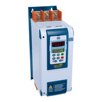
WEG SSW-06.0312 User Manual (160 pages)
SSW-06 series.
Brand:
WEG
| Category:
Controller
| Size: 16.04 MB
Table of Contents
Table of Contents
5
Parameters
9
Quick Parameter Reference, Fault and Status Messages
9
I Parameters
16
Fault Messages
17
Other Messages
17
CHAPTER 1 Safety Notices
18
Safety Notices in the Manual
18
Safety Notice on the Product
18
Preliminary Recommendations
19
CHAPTER 2 General Information
20
About this Manual
20
Software Version
20
About the Soft-Starter SSW-06
20
Soft-Starter SSW-06 Identification
23
Receiving and Storage
25
CHAPTER 3 Installation and Connection
26
Mechanical Installation
26
Environment Conditions
26
Dimensions of the Soft-Starter SSW-06
26
Mounting Inside a Panel
28
Mounting on a Surface
30
Electrical Installation
31
Power Terminals
32
Location of the Power/ Grounding, Control Connections and Fan Voltage Selection
36
Recommended Power/Grounding Cables
38
Power Supply Capacity
40
Recommended Fuses
40
Standard Three-Wire Connection (P150=0=Inactive)
41
Inside Delta Motor Connection (P150=1=Active)
42
Grounding Connections
43
Signal and Contro Connections
45
RS-232, X2 Serial Communication Connection
48
RS-485, XC8 Isolated Serial Communication Board Connection
48
XC6 Fieldbus Communication Board Connection
48
Recommended Set-Ups
48
Recommended Set-Ups by Keypad (HMI) Command with Isolating Contactor. Notes in 3 .3
50
Recommended Set-Ups by Keypad (HMI) Command with Circuit-Breaker. Notes in 3.3
50
Recommended Set-Ups with Command Via Two-Wire Digital Inputs. Notes in 3.3
51
Recommended Set-Ups with Command Via Three-Wire Digital Inputs. Notes in 3.3
51
Recommended Set-Ups with Command Via Three-Wire Digital Input and Inside Delta Motor Connection. Notes in
52
And 3.2.5.2
52
Recommended Set-Ups with Command Via Three-Wire Digital Input or Serial Communication. Notes in 3.3
52
Recommended Set-Ups with Command Via Three-Wire Digital Input or Fieldbus Communication. Notes in 3.3
53
Recommended Setup with Command Via Digital Inputs and Direction of Rotation
53
Recommended Setup with Command Via Digital Inputs and Reverse Braking
54
Recommended Setup with Command Via Digital Inputs and Optimal Braking
54
Recommended Setup with Command Via Digital Inputs and DC-Braking
55
Recommended Setup with Command Via Digital Inputs and External By-Pass Contactor
55
Symbols
56
European Directives for Electromagnetic Compatibility Requirements for Installation
57
Installation
57
CHAPTER 4 Keypad (HMI) Operation
58
Description of the Keypad (Hmi-Ssw06)
58
Use of the Keypad (HMI)
60
Keypad Use for Soft-Starter SSW-06 Operation
60
HMI Display-Signaling Indications
61
Parameter Viewing and Programming
62
CHAPTER 5 Start-Up
64
Power-Up Preparation
64
Initial Power-Up
65
Start-Up
72
Type of Control: Voltage Ramp
73
CHAPTER 6 Detailed Parameter Description
76
Access and Read-Only Parameters - P000 to P099
76
Regulation Parameters - P100 to P199
81
Configuration Parameters - P200 to P299
90
Communication Parameters - P300 to P399
103
Motor Parameters - P400 to P499
105
Special Function Parameters - P500 to P599
106
CHAPTER 7 Applications and Programming
120
Starting by Voltage Ramp (P202=0)
122
Starting by Current Limit (P202=1)
123
Starting by Current Ramp (P202=4)
125
Starting with Pump Control (P202=2)
126
Starting with Torque Control (P202=3)
128
Loads with Constant Torque (P202=3 and P120=1 Point)
129
Loads with Constant Torque and S Speed Curve
130
Loads with Quadratic Torque and S Speed Curve
130
Loads with Quadratic Torque and Linear Speed Curve
131
Loads with Quadratic Torque and Higher Initial Torque
131
Hydraulic Pump Load Type (P202=3)
132
Thermal Classes
135
Suggestions about Thermal Class Setting
135
Example of How to Program the Thermal Class
136
Time Reduction When Changing from Cold Starting to Hot Starting
137
Service Factor
137
CHAPTER 8 Diagnosis and Troubleshooting
138
Faults and Possible Causes
138
Troubleshooting
142
Preventive Maintenance
143
Cleaning Instructions
144
Spare Parts List
144
CHAPTER 9 Options and Accessories
145
Remote Keypad (HMI) and Cables
145
For the Soft-Starter SSW-06
147
Fieldbus Communication Kits
148
CHAPTER 10 Technical Specifications
150
Currents and Ratings According to Ul508
150
Currents and Ratings for IP55, IV Pole weg Motor
151
Power Data
152
Electronics/Programming Data
152
Mechanical Data
154
Advertisement
Advertisement
Related Products
WEG SSW-06.0365
WEG SSW-06.0205
WEG SSW-06.0412
WEG SSW-06.0480
WEG SSW-06.0604
WEG SSW-06.0085
WEG SSW-06.0670
WEG SSW-06.0820
WEG SSW-06.0950
WEG SSW-06.0170
WEG Categories
DC Drives
Controller
Circuit breakers
Control Unit
Inverter
More WEG Manuals
Login
Sign In
OR
Sign in with Facebook
Sign in with Google
Upload manual
Upload from disk
Upload from URL