Sign In
Upload
Manuals
Brands
WAGNER Manuals
Security Sensors
TITANUS RACK-SENS 1U
WAGNER TITANUS RACK-SENS 1U Manuals
Manuals and User Guides for WAGNER TITANUS RACK-SENS 1U. We have
1
WAGNER TITANUS RACK-SENS 1U manual available for free PDF download: Technical Manual
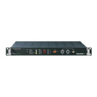
WAGNER TITANUS RACK-SENS 1U Technical Manual (143 pages)
Air Sampling Smoke Detection System
Brand:
WAGNER
| Category:
Security Sensors
| Size: 3 MB
Table of Contents
Table of Contents
3
General
7
Introduction
7
Safety Information
7
Warranty
8
Copyright
8
Packaging
9
Disposal
9
Instructions for the User
10
Product Description
11
Features of the TITANUS RACK·SENS
11
Air Sampling Smoke Detection System
11
Areas of Application
14
Technical Description
17
System Description
17
Functional Description
18
Display Panel
20
And Accessories
22
Overview
22
Air Sampling Smoke Detection System
23
Operation
26
Diagnostics Tool
28
Optical Indicator
29
Pipe System
30
Complete Overview of Available Pipe Components
31
Standard Sampling Pipe
32
Aspiration Reduction Films
33
Integrated Air Filter
34
Shutdown Module
34
Temperature Sensor
35
Door Contact Switch
35
Technical Data
37
Pipe System TITANUS RACK·SENS
39
TITANUS RACK·SENS 1U Accessories
40
Design
41
General
41
Regulations
41
Positioning the TITANUS RACK·SENS® 1U and the Pipe System for Detection
42
Project Planning - Smoke Aspiration
43
Project Planning for 19" Cabinets
44
Smoke Detection in 19" Cabinets with Standard Sampling Pipe
44
Smoke Detection in 19" Cabinets with Customised Sampling Pipe
46
Protection for Cabinets in Rows or Consecutive Cabinets
51
General Pipe System Project Planning
54
Pipe System Configurations
54
Sensitivity
57
Pipe Design
59
Simplified Pipe Design (Local Application Protection)
59
I-Pipe System
59
U-Pipe System
60
M- Pipe System
61
Double-U-Pipe System
62
Temperature Monitoring
63
Device Shutdown
63
Door Contact Switch
63
Air Flow Monitoring
64
General Project Planning Instructions for Shutdown and Cooling Shutdown
65
Calculating Detection Sensitivity
66
Power Supply
67
Calculating Capacity for External Power Supply
67
Installation and Wiring of TITANUS RACK·SENS
69
Titanus Rack·sens 1U
69
General
69
Installation Site
70
Mounting the TITANUS RACK·SENS
70
Installation
71
Connection for Sampling Pipe
72
Electrical Connection
73
Connecting the External 24 V Supply
75
Connection to Mains Supply 230 V
76
Circuit Diagram TITANUS RACK·SENS
77
Device "Reset" Circuit Diagram for Individual TITANUS RACK·SENS
78
Devices
78
Device "Reset" Circuit Diagram for Several TITANUS RACK·SENS
79
Devices
79
Installation and Connection of Door Contact Switch
80
Installation and Connection of Temperature Sensors
83
Installation and Connection of Shutdown Module (Low Power)
85
Installation and Connection for Device Shutdown (High Power)
87
Connecting the Response Indicator to the TITANUS RACK·SENS
88
Installation of the Pipe System
91
Patented Air Sampling Points
94
Monitoring in Forced Air Flow Systems (Ventilation or Climatic Applications)
96
Detection at Air Inlets/Outlets
96
Commissioning
97
Operating TITANUS RACK·SENS
97
Key Switch
97
Config. Temp. Button
97
Reset and Buzzer off Button
98
Air Flow Initialisation
99
Commissioning TITANUS RACK·SENS
100
Termination of Unused Inputs
100
Commissioning Procedure
101
Settings Adjustment with the Diagnostics Tool
103
Settings for Main Board and Detector Module
104
Alarm Delay Setting
105
Air Flow Range Setting
105
Fault Delay Setting
106
Pre-Warning Period Setting
106
Buzzer Setting
107
Fault Indicator Setting
107
Dynamic Air Flow Setting
107
Sensitivity Setting (Main Alarm)
108
Pre-Alarm Threshold Setting
108
Setting LOGIC·SENS
108
Air Flow Initialisation Setting
109
Setting Height above Normal Sea Level (NN)
110
Setting the Current Air Pressure
110
Fan Voltage Setting
110
Setting the Programmable Relays and the Temperature Alarm
111
Data Logging
114
Example of a Commissioning Log (2 Pages)
115
Testing the Detection Unit and Alarm Forwarding
117
Testing Response Behaviour in Cabinets
118
Testing Air Flow Monitoring
119
Testing Fault Forwarding
120
Installing the Diagnostics Software and the USB Driver
121
Installing the USB Driver
122
Operation Using DIAG
123
Maintenance
125
Procedure for Servicing
125
Trouble Shooting
126
Inspection
127
Visual Inspection
127
Testing Detector and Alarm Forwarding
127
Filter Replacement in the Integrated Air Filter
128
Backup Battery Replacement
129
Checking the Air Flow Sensor Adjustment
131
Checking the Detector Status
133
Testing Air Flow Monitoring
133
Testing Fault Forwarding
133
Maintenance Intervals
134
Advertisement
Advertisement
Related Products
WAGNER ProjectPro 117 0418B
WAGNER ProjectPro 117
WAGNER Project 115 0418A
WAGNER Wildcat 10-70
WAGNER Wildcat 18-40
WAGNER Control Stainer 150
WAGNER TwinControl 18-40 ABS
Wagner SuperFinish 17ex
WAGNER TOPFINISH Bell 1S
WAGNER TOPFINISH Bell 1S ECH
WAGNER Categories
Paint Sprayer
Lantern
Water Pump
Power Tool
Tools
More WAGNER Manuals
Login
Sign In
OR
Sign in with Facebook
Sign in with Google
Upload manual
Upload from disk
Upload from URL