Sign In
Upload
Manuals
Brands
WABECO Manuals
Lathe
D6000 hs
User Manuals: WABECO D6000 hs CNC Lathe
Manuals and User Guides for WABECO D6000 hs CNC Lathe. We have
1
WABECO D6000 hs CNC Lathe manual available for free PDF download: Operating Instructions Manual
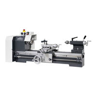
WABECO D6000 hs Operating Instructions Manual (168 pages)
CNC lathes With prismatic cast iron bed
Brand:
WABECO
| Category:
Lathe
| Size: 15 MB
Table of Contents
Table of Contents
3
Declaration of Conformity for D6000 - D6000 Hs
8
Declaration of Conformity for D6000-C - D6000-C Hs
9
Declaration of Conformity for CC-D6000 - CC-D6000 Hs
10
1 Important Safety Notes
11
Intended Use
11
Improper and Incorrect Use
11
Modifications to the Machine
11
Safety Regulations for Proper Use
11
Safety Features
14
For All Lathes
14
For Lathes to be Mounted to a CNC Control
14
For CNC Lathes
14
Explanations of the Symbols
15
2 Delivery and Set up
15
Transporting the Machine
16
3 Putting into Operation
17
For All Lathes
17
For All CNC Lathes
17
Setting up and Connecting the Control Computer
17
4 Specifications Regarding the Machine
18
Identification of the Model
18
Noise Emission Declaration for D6000 - D6000 Hs
18
Technical Data for D6000 - D6000 Hs
19
Dimensions of D6000 with 1.4 Kw Motor with Trapezoidal-Threaded Spindle
20
Front View
20
Side View
20
Dimensions of D6000 Hs with 2.0 Kw Motor with Trapezoidal-Threaded Spindle
21
Front View
21
Side View
21
Dimensions of D6000 with 1.4 Kw Motor with Ball Screw Spindle Front View
22
Dimensions of D6000 with 1.4 Kw Motor with Ball Screw Spindle Side View
22
Dimensions of D6000 Hs with 2.0 Kw Motor with Ball Screw Spindle Front View
23
Dimensions of D6000 Hs with 2.0 Kw Motor with Ball Screw Spindle, Side View
23
Noise Emission Declaration for D6000-C - D6000-C Hs
24
Technical Data for D6000-C - D6000-C Hs
25
Dimensions of D6000-C with 1.4 Kw Motor with Trapezoidal-Threaded Spindle
26
Front View
26
Side View
26
Dimensions of D6000-C Hs with 2.0 Kw Motor with Trapezoidal-Threaded Spindle
27
Front View
27
Side View
27
Dimensions of D6000-C with 1.4 Kw Motor with Ball Screw Spindle
28
Front View
28
Side View
28
Dimensions of D6000-C Hs with 2.0 Kw Motor with Ball Screw Spindle
29
Front View
29
Side View
29
Noise Emission Declaration for CC-D6000 - CC-D6000 Hs
30
Technical Data for CC-D6000 - CC-D6000 Hs
31
Dimensions of CC-D6000 with 1.4 Kw Motor with Trapezoidal-Threaded Spindle
32
Front View
32
Side View
32
Dimensions of CC-D6000 Hs with 2.0 Kw Motor with
33
Dimensions of CC-D6000 with 1.4 Kw Motor with Ball Screw Spindle
34
Front View
34
Side View
34
Dimensions of CC-D6000 Hs with 2.0 Kw Motor with Ball Screw Spindle
35
Front View
35
Side View
35
Revolution Selection
36
Diagram for Reading off the Revolutions
36
Revolution Changer for 1.4 Kw Motor
37
Revolution Changer for 2.0 Kw Motor
38
Electrical Equipment 1.4 Kw Motor
39
Electrical Equipment 2.0 Kw Motor
39
Achieving Optimum Results and Avoiding Incorrect Usage
40
6 Thread Cutting and Automatic Feed
42
Thread Cutting
42
Tumbler Gear Drive
43
Use of Change Gears
44
7 Maintenance
46
8 Lubrication of the Machine
47
9 Readjusting the Main Spindle
48
10 Overload Coupling
48
11 Readjustment of the Bearing Clearance of the Lead Screw
49
12 Tool Skid - Transverse Skid
50
13 Tool Skid - Longitudinal Skid
52
14 Tailstock
53
15 And 4 Jaw Lathe Chuck
54
16 Operational Faults and the Elimination of such
55
17 Operating Elements
58
D6000 Lathes with 1.4 Kw Motor with Trapezoidal-Threaded Spindle
58
D6000 Lathes with 2.0 Kw Motor with Trapezoidal-Threaded Spindle
59
D6000 Lathes with 1.4 Kw Motor with Ball Screw Spindle
60
D6000 Lathes with 2.0 Kw Motor with Ball Screw Spindle
61
D6000-C Lathes with 1.4 Kw Motor with Trapezoidal-Threaded Spindle
62
D6000-C Lathes with 2.0 Kw Motor with Trapezoidal-Threaded Spindle
63
D6000-C Lathes with 1.4 Kw Motor with Ball Screw Spindle
64
D6000-C Lathes with 2.0 Kw Motor with Ball Screw Spindle
65
Switch Cover on CNC Operating Console
66
For CC-D6000 Lathes with 1.4 Kw Motor
66
Switch Cover on CNC Operating Console
67
For CC-D6000 Lathes with 2.0 Kw Motor
67
CC-D6000 Lathes with 1.4 Kw Motor with Trapezoidal-Threaded Spindle
68
CC-D6000 Lathes with 2.0 Kw Motor with Trapezoidal-Threaded Spindle
69
CC-D6000 Lathes with 1.4 Kw Motor with Ball Screw Spindle
70
CC-D6000 Lathes with 2.0 Kw Motor with Ball Screw Spindle
71
18 Drawings and Legends
72
Electronic Console, 1.4 Kw Motor
72
Protective Hood, Drive 1.4 Kw Motor
75
Protective Hood, Drive 2.0 Kw Motor
76
Electronic Console, 2.0 Kw Motor
78
Headstock
81
Headstock - Transmission with Trapezoidal-Threaded Spindle
82
Headstock - Tumbler Gear with Trapezoidal-Threaded Spindle
83
Headstock - Transmission with Ball Screw Spindle
84
Headstock - Tumbler Gear with Ball Screw Spindle
85
Bed with Lead Screw with Trapezoidal-Threaded Spindle
86
Bed with Lead Screw with Ball Screw Spindle
88
Change Gear Quadrant for Trapezoidal-Threaded Spindle and Ball Screw Spindle
92
Tool Skid - Transverse Skid
94
Tool Skid - Lock Plate
96
Tool Skid - Longitudinal Skid
98
Transverse Skid with Lock Plate with Ball Screw Spindle
100
Tailstock
102
Motor for Control of the X-Axis
104
Motor for Control of the Z-Axis
106
Operating Console for 1.4 Kw Motor
108
Operating Console for 2.0 Kw Motor
112
Bracket Arm for Operating Console
116
Industrial Screen and Membrane Keyboard
118
Industrial Screen and Membrane Keyboard Specifically for 1.4 Kw Motor
120
Industrial Screen and Membrane Keyboard Specifically for 2.0 Kw Motor
122
Bracket Arm for Industrial Screen and Membrane Keyboard
124
Lead Screw Cover
125
CNC 8-Fold Tool Changer
126
Speed Sensor (Optional) for 2.0 Kw Motor with Safety Cabin
128
For 1.4 Kw Motor with and Without Safety Cabin
128
19 Circuit Diagram
130
For 1.4 Kw Motor
130
For 1.4 Kw Motor and Safety Cabin with Nccad Basic
131
For 1.4 Kw Motor and Safety Cabin with Nccad Professional
132
For 2.0 Kw Motor
133
For 2.0 Kw Motor and Safety Cabin with Nccad Basic
135
For 2.0 Kw Motor and Safety Cabin with Nccad Professional
135
Industrial Screen and Membrane Keyboard Specifically for 1.4 Kw Motor
136
Industrial Screen and Membrane Keyboard Specifically for 2.0 Kw Motor
137
Multiphase Motor with End Stop
138
Key for Circuit Diagram
139
20 Camlock Main Spindle (Optional)
141
Undoing a Chuck or Holding Flange from the Camlock
141
Blocking a Chuck or Holding Flange on the Camlock
141
21 Shavings Tank with Spray Protection Wall (Optional)
142
Setting up the Shavings Tank with Spray Protection Wall
142
Mounting the Shavings Tank with Spray Protection Wall on the
143
Drawing and Legend
144
22 Coolant System (Optional)
145
Setting up the Coolant System
145
Mounting of the Coolant System to the
145
Safety Regulations for the Handling of Cooling Lubricant
146
Filling the Coolant System
147
Operating the Coolant System Without CNC Control
147
Operating the Coolant System with CNC Control
148
Positioning the Segmented Coolant Hose
149
Controlling the Flow of Coolant Using the Coolant Shut-Off Valve
149
Drawing and Legend
150
23 Safety Cabin (Optional)
152
Setting up the Safety Cabin
152
Mounting of the Safety Cabin to the Tool Cabinet (Optional)
152
Safety Regulations for the Handling of Cooling Lubricant
153
Filling the Coolant System Integrated in the Safety Cabin
153
Operating the Coolant System with CNC Control
153
Positioning the Segmented Coolant Hose
153
Controlling the Flow of Coolant Using the Coolant Shut-Off Valve
153
Drawing and Legend
154
24 Fixed Bezel (Optional)
156
Operating the Fixed Bezel
156
Drawing and Legend
157
25 Moving Bezel (Optional)
158
Operating the Moving Bezel
158
Drawing and Legend
159
26 Tensioning Bracket with Milling Machine Table (Optional)
160
Mounting the Tensioning Bracket with Milling Machine Table to the Lathe
160
Operating Elements
161
Feed Motion of the Milling Machine Table
161
Adjustment of the Dovetail Guide
162
Alignment of the Milling Machine Table
162
Lubrication of the Tensioning Bracket with Milling Machine Table
162
Drawing and Legend
163
27 Adjustable Longitudinal Stopper (Optional)
165
Mounting of the Adjustable Longitudinal Stopper
165
Drawing and Legend
166
28 Collet Chuck (Optional)
167
Mounting the Collect Chuck
167
Drawing and Legend
167
Installation and Removal of Collets
168
Advertisement
Advertisement
Related Products
WABECO D6000
WABECO D6000-C
WABECO D6000-C hs
Wabeco D3000 E
Wabeco D2400 E
Wabeco D2000E
wabeco D4000 E
WABECO D2400
WABECO D2000
WABECO D3000
WABECO Categories
Lathe
Drill
Power Tool
More WABECO Manuals
Login
Sign In
OR
Sign in with Facebook
Sign in with Google
Upload manual
Upload from disk
Upload from URL