Sign In
Upload
Manuals
Brands
Volvo Penta Manuals
Engine
TAD1242GE
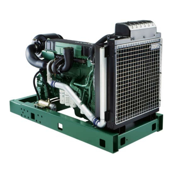
Volvo Penta TAD1242GE Manuals
Manuals and User Guides for Volvo Penta TAD1242GE. We have
3
Volvo Penta TAD1242GE manuals available for free PDF download: Operator's Manual, Technical Description
Volvo Penta TAD1242GE Technical Description (62 pages)
GENSET ENGINE
Brand:
Volvo Penta
| Category:
Engine
| Size: 0 MB
Table of Contents
Technical Description
1
Features
1
Technical Data
2
Dimensions TAD1242GE
2
Design and Operation
3
System Description EDC III
3
Control Module
3
Fuel Management
3
Calculation of Fuel Quantity
4
Cylinder Balance
4
Diagnostic Function
4
Idle Adjustment (Low Idle)
4
Component Description
5
Water Monitor, Fuel Pre-Filter
5
Tachometer Sensor, Camshaft
5
Oil Pressure/Temperature Sensor
5
Tachometer Sensor, Flywheel
6
Charge Air Pressure/Temperature Sensor
6
Coolant Temperature Sensor
6
Fuel Pressure Monitor
6
Coolant Level Monitor
7
Electronic Control Unit (ECU)
7
Control Interface Unit
7
Unit Injectors
8
Generator
8
Starter Motor
8
Component Diagram and Location
9
Limit Values
10
Alarm Values
10
Alarm Limits TAD1240–42GE/VE
10
Limit Values, Electronic Control Unit (ECU) TWD1240VE
11
Alarm Limits
11
Limp-Home Values
12
Repair Instructions
13
When Working with EDC III
13
Electronic Control Unit (ECU), Replacement
14
Start with Booster Batteries
15
Functionality Check
16
PC Diagnostics Program
16
Fault Detection
17
Symptoms and Possible Causes
17
If the Diagnosis Button’s Indicator Blinks
18
Notification of Disturbance if the Diagnostic Function
18
Guidance for Fault Detection if the Diagnosis Button
18
Reading out Error Codes
19
Erasing Error Codes
19
Error Codes EDC III
20
Water in the Fuel or Low Fuel Pressure
20
Low Coolant Level
20
Tachometer Sensor, Flywheel. no Signal
20
RPM Sensor, Camshaft. no Signal
21
RPM Sensor, Camshaft. Abnormal Frequency
21
RPM Potentiometer Connected to Engine Control Unit (ECU)
21
RPM Potentiometer Connected to the Engine Control Unit (ECU)
21
Oil Pressure Sensor. Short to Positive (+)
22
Oil Pressure Sensor. Interrupted or Shorted to Negative (-)
22
Charge Air Temperature Sensor. Interrupted or Shorted to Positive (+)
22
Charge Air Temperature Sensor
22
Charge Air Pressure Sensor. Short to Positive (+)
23
Oil Temperature Sensor. Interrupted or Shorted to Positive (+)
23
Oil Temperature Sensor. Short to Negative
23
Oil Pressure Alarm, Circuit Interrupted
23
Alarm for High Coolant Temp
24
Lamp to Indicate Operation. Interruption
24
Lamp to Indicate Operation. Short to Negative (-)
24
Overspeed Alarm. Circuit Interruption
24
Low Coolant Alarm. Circuit Interruption
25
Low Coolant Alarm. Short to Negative (-)
25
Low Coolant Alarm. Short to Positive (+)
25
Start Relay on Starter Motor
25
Stop Input Engine Control Unit (ECU)
26
Main Relay. Short to Positive (+)
26
Start Input on CIU. Short to Negative (-)
26
Start Input on CIU. Short to Positive (+) or Activated too Long
26
Preheating Relay. Connection Interruption
27
Preheating Relay. Short to Negative (-)
27
Preheating Relay. Short to Positive (+)
27
Oil Temperature Is too High
27
Datalink Error (CAN)
28
Oil Pressure Is too Low
28
Unit Injector Cylinder #1. Electronic Error
28
Electronic Fault Detection
37
Functionality Check of Lines and Connectors
37
Contact Problems
37
Fault Detection on Cables and Connectors
38
Interruption
38
Contact Resistance and Oxidation
38
Splicing Electrical Cable for Cable Glove
39
Checking the Combined Sensor for Charge Air Pressure/ Temperature
40
Checking the Coolant Temperature Sensor
40
Checking Charge Air Pressure
40
Checking Charge Air Temperature
40
Checking Water Monitor, Fuel Pre-Filter
41
Checking the Camshaft and Flywheel Sensors
41
Checking the Combined Sensor for Oil Pressure/Temperature
42
Checking the Coolant Level Sensor
42
Checking the Function of Oil Pressure
42
Checking the Function of Oil Temperature
42
Fault Detection on Unit Injectors
43
Error Symptoms
43
Error Causes
43
Determine or Rule out Error Causes Using the PC Diagnostics Program
43
Fault Detection on Starter Motor and Lines
44
Checking Voltage Feed
44
Carbon Brushes
44
Carbon Brush Appearance
44
Functionality Check of Relays
45
Fault Detection on the Generator
46
Regulator
47
Checking Positive Output Diodes
48
Checking Negative Output Diodes
49
Checking Excitation Diodes
50
Checking Stator Windings
51
Overload Test on Stator
51
Checking the Rotor
52
Overload Test on Rotor
52
Electrical System
53
Important about the Electrical System
53
Electric Welding
53
Electrical System, Overview
54
TWD1240VE Stand Alone
54
TWD1240VE with CIU, CAN Based SAE J1939
54
TWD1240VE Power Pack
55
TAD1240–42GE with CIU, CAN Based SAE J1939
55
TAD1241–42VE with CIU, CAN Based SAE J1939
55
TAD1240–42GE Stand Alone
56
TAD1241–42VE Stand Alone
56
Cable Colors
57
Wiring Diagram, Control Interface Unit (CIU) – Power Pack
60
Index
61
Advertisement
Volvo Penta TAD1242GE Operator's Manual (76 pages)
Brand:
Volvo Penta
| Category:
Engine
| Size: 2 MB
Table of Contents
Table of Contents
3
Safety Information
4
Safety Instructions for Operation and Maintenance
5
Introduction
8
Environmental Responsibility
8
Running-In
8
Fuel and Oils
8
Maintenance and Reserve Parts
8
Certified Engines
9
Presentation
10
Technical Description
10
Identification Numbers
11
Orientation
12
Edc III
13
Instrument EDC III
14
DCU (Display Control Unit)
15
Starting the Engine
21
Before Starting
21
Starting Procedure EDCIII
22
Volvo Penta Start Lock
23
Start-Up under Extreme Cold
24
Never Use Starting Fluid
25
Start-Up with Helper Batteries
25
Operation
26
Checking Instruments
26
Fault Indication
26
Operation at Low Load
26
Shutting down the Engine
27
Prior to Shut-Down
27
Shut-Down
27
After Shut-Down
27
Extra Shut-Down
27
Maintenance Schedule
28
Newly Rebuilt Engine
29
Maintenance
30
Engine, General
30
Lubrication System
34
Cooling System
37
Fuel System
43
Electric System
47
Preparation for Storage
51
Preparation after Storage
52
Troubleshooting
53
Symptoms and Possible Causes
53
Diagnostic Function
54
Fault Messages
54
Effect on Engine
54
Operation
55
Fault Codes
57
Technical Data
66
General
66
Lubrication System
66
Fuel System
67
Cooling System
67
Electric System
68
Volvo Penta TAD1242GE Technical Description (61 pages)
Genser Engine, 1500 rpm, 354 kW (481 hp) – 1800 rpm, 387 kW (526 hp)
Brand:
Volvo Penta
| Category:
Engine
| Size: 1 MB
Table of Contents
Design and Operation
3
Control Module
3
Fuel Management
3
Component Description
5
Coolant Temperature Sensor
6
Electronic Control Unit (ECU)
7
Unit Injectors
8
Starter Motor
8
Alarm Values
10
Limit Values
10
Alarm Limits
11
Repair Instructions
13
Functionality Check
16
Fault Detection
17
Symptoms and Possible Causes
17
Diagnostic Function
18
Checking the Coolant Temperature Sensor
40
Carbon Brushes
44
Electrical System
53
Electric Welding
53
Electrical System, Overview
54
Advertisement
Advertisement
Related Products
Volvo Penta TAD1240GE
Volvo Penta TAD1241GE
Volvo Penta TAD1241VE
Volvo Penta TAD1242VE
Volvo Penta TAD1631GE
Volvo Penta TAD1642VE-B
Volvo Penta TAD1341GE
Volvo Penta TAD1350GE
Volvo Penta TAD1340VE
Volvo Penta TAD1343VE
Volvo Penta Categories
Engine
Control Systems
Outboard Motor
Marine Equipment
Control Panel
More Volvo Penta Manuals
Login
Sign In
OR
Sign in with Facebook
Sign in with Google
Upload manual
Upload from disk
Upload from URL