Sign In
Upload
Manuals
Brands
View Manuals
Measuring Instruments
Benchmark 450
View Benchmark 450 Metrology System Manuals
Manuals and User Guides for View Benchmark 450 Metrology System. We have
2
View Benchmark 450 Metrology System manuals available for free PDF download: Service Manual, Installation Manual
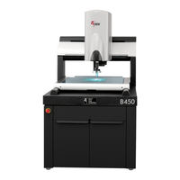
View Benchmark 450 Service Manual (311 pages)
Brand:
View
| Category:
Laboratory Equipment
| Size: 7 MB
Table of Contents
Table of Contents
5
Important System Labels
11
1 About this Manual
13
What this Chapter Contains
13
Who Should Read this Manual
13
Required Knowledge
14
What's in this Manual
14
Where to Read more
15
Where to Get Help
16
2 General Description
17
What this Chapter Contains
17
What Is the Benchmark 450 System
17
Benchmark 450 System Main Components
18
Coaxial Light, Programmable Ring Light, & Backlight
19
Dual Magnification Optical System
20
Computer & User-Interface Components
21
Mouse
21
Keyboard
21
Joystick
21
3 Safety Information
23
What this Chapter Contains
23
Emergency Stops
23
System Status Leds
24
System Power
25
System Lockout
26
Safety Guidelines
27
4 Installation
29
What this Chapter Contains
29
Choosing an Installation Site
30
Benchmark 450 System Layout
31
Receiving, Unpacking, & Inspecting the System
32
Moving & Installing the System
33
Connecting the System
34
Powering up the System & Launching the VMS Software24
36
Operation Checks
37
Post Installation Checklist
38
Shutting down the System
39
Installing the X, Y, & Z Shipping Restraints
40
Fixture Mounting Holes
44
5 Principles of Operation & Interconnections
45
What this Chapter Contains
45
Overview of Operation
46
Image Acquisition, Processing, & Display
47
Motion Control
48
Y-Axis Motion
48
Z-Axis Motion
49
Illumination Sources
50
Optional LED Grid Projector
51
Optional Ronchi Shuttle Grid Assembly
52
Optional Accucentric Assembly
53
Zeroing the Stage
53
Benchmark 450 Schematic Diagram
53
6 Preventive Maintenance
57
What this Chapter Contains
57
Preventive Maintenance Schedule
58
Cleaning the User Components
59
Cleaning the Joystick
59
Cleaning the Mouse
59
Cleaning the Flat Panel Display
59
Cleaning the Keyboard
59
Cleaning the Stage, External Surfaces, & Stage Glass
60
Cleaning the Stage
60
Cleaning External Surfaces
60
Cleaning the Stage Glass
61
Leveling the Stage Glass
62
Cleaning & Lubricating the X-Axis and Y-Axis Rails
68
Cleaning & Lubricating the X-Axis Rails
69
Cleaning & Lubricating the Y-Axis Guide Rails
71
Cleaning the Magnification Lens
73
Cleaning the LED Programmable Ring Light (PRL)
75
Checking for Dirt in the Images of the Video Cameras
76
Verifying Proper System Operation
76
7 Troubleshooting
77
What this Chapter Contains
77
Before You Begin
78
DSP Multi Axis PCBA Diagnostic Leds & Test Points
79
DSP Multi Axis PCBA Diagnostic Leds
79
Magnetic Limit Codes (DS7)
84
DSP Multi Axis PCBA Test Points
85
Dual Mag Optics PCBA Diagnostic Leds & Test Points
87
Dual Mag Optics PCBA Diagnostic Leds
87
Dual Mag Optics PCBA Test Points
90
Z Brake Control PCBA Diagnostic Leds & Test Points
92
Z Brake Control PCBA Diagnostic Leds
92
Z Brake Control PCBA Test Points
95
LED Driver PCBA Diagnostic Leds & Test Points
97
LED Driver PCBA Diagnostic Leds
97
LED Driver PCBA Test Points
99
Measuring the Resistance of the Drewire Terminations
101
Identifying Problems with the Benchmark 450 System
102
Start-Up Troubleshooting
102
Illumination Troubleshooting
103
Motion Troubleshooting
107
Video Troubleshooting
116
Identifying Problems with the System Computer & User-Interface Components
118
Start-Up & General Performance
118
Communications
119
Joystick
119
Troubleshooting the Joystick
120
Keyboard
124
Flat Panel Display
124
Recovering from Unexpected Z-Axis Contact
126
8 Service Adjustments
129
What this Chapter Contains
129
Benchmark 450 Service Adjustments
130
Integrated Workstation Adjustment
131
Dual Magnification Optical System Adjustments
132
Component Location
132
Sequence of Optical Adjustments
134
Ronchi Shuttle Window Position Adjustment
135
Ronchi Shuttle Opto Switch Flag & End Limits Adjustment
136
Ronchi Grid Rotation Adjustment
138
Camera Parfocal Adjustment
139
Camera Parfocal Adjustment (Systems Equipped with Ronchi Grid)
142
LED Grid Projector Focus Adjustment
146
Camera Par-Center (Coaxial) Adjustment
148
8.4.10 Camera Rotation Adjustment
151
Lens Calibration
153
Accucentric Assembly Alignment
155
LED Programmable Ring Light (PRL) Adjustments
158
Centering the PRL
159
Adjusting the PRL Height
162
Setting up the PRL Lights
165
Checking the PRL Light Setup with the Light Test Part Program
169
9 Parts Repair & Replacement
171
What this Chapter Contains
171
Repairing & Replacing Parts on Your System
172
Removing the Benchmark 450 Covers
174
Removing the Front Cover and Z-Axis Cover
174
Removing the Rear Bridge Cover
175
Removing the Lower Bridge Cover
176
Removing the Electronics Enclosure Panel
177
Replacing the Magnification Lens
178
Replacing the High & Low Mag Cameras
179
Replacing the Programmable Ring Light (PRL)
181
Replacing the Accucentric Assembly
183
Replacing the Scale Reader Heads
185
Replacing the X-Axis Scale Reader Head
186
Replacing the Y-Axis Scale Reader Head
190
Replacing the Z-Axis Glass Scale and Reader Head
193
Replacing the Motors
196
Replacing the X-Axis Motor
197
Replacing the Y-Axis Motor
199
Replacing the Z-Axis Motor
202
Replacing the Main Power Fuse(S)
206
Replacing the Pcbas
207
9.11.1 Replacing the DSP Multi Axis PCBA
208
9.11.2 Replacing the Z Brake Control PCBA
210
9.11.3 Replacing the LED Driver PCBA
212
9.11.4 Replacing the Dual Mag Optics PCBA
214
Replacing the Universal Multisensor PCBA
216
Replacing the Micro Theta Control PCBA
218
Replacing the Power Supplies
220
9.12.1 Replacing the 24 Volt Power Supply
221
9.12.2 Replacing the 48 Volt Power Supply
224
9.12.3 Replacing the ATX Power Supply
227
Replacing the Fans
230
9.13.1 Replacing the Exhaust Fan
231
9.13.2 Replacing the Intake Fan
233
AVMS System Certification & Verification 7.02
235
What this Appendix Contains
235
General Guidelines
235
Handling & Cleaning Grid Plates, Scales, & Lenses
236
Wringing Gage Blocks
236
System Certification
238
Certification Setup
239
XY Certification
243
Z Certification
247
System Verification
257
Verification Setup
258
XY Verification
262
Z Verification
266
TTL Laser Calibration
277
What this Appendix Contains
277
TTL Laser Alignment
278
TTL Laser Calibration
290
TTL Laser Verification
292
Accessing VMS Parameters
293
What this Appendix Contains
293
Accessing Basic Parameters
294
Accessing Advanced Parameters
295
Loading Parameters
296
Software Installation
297
What this Appendix Contains
297
VMS Software Installation
298
Elements Software Installation
303
Index
307
Advertisement
View Benchmark 450 Installation Manual (47 pages)
Brand:
View
| Category:
Measuring Instruments
| Size: 1 MB
Table of Contents
Table of Contents
5
Important System Labels
7
1 About this Manual
9
What this Chapter Contains
9
Who Should Read this Manual
9
Required Knowledge
9
What's in this Manual
10
Where to Get Help
10
2 System Overview
11
What this Chapter Contains
11
What Is the Benchmark 450 System
11
System Components
12
How the System Operates
13
3 Safety Information
15
What this Chapter Contains
15
Emergency Stops
15
System Status Leds
16
System Power
17
System Lockout
18
Safety Guidelines
19
4 Installation
21
What this Chapter Contains
21
Choosing an Installation Site
22
Benchmark 450 System Layout
23
Unpacking the Machine
24
Removing the X, Y, and Z Restraints
27
Connecting the System
30
Installing the Stage Glass
32
Leveling the Stage Glass
33
5 System Startup & Shutdown
39
What this Chapter Contains
39
System Power-Up Procedure
40
System Shutdown Procedure
40
Stopping Stage Motion
41
Operation Checks
42
Running a Part Inspection Program
43
Fixture Mounting Holes
45
Advertisement
Related Products
View Benchmark 250
View Categories
Laboratory Equipment
Accessories
Measuring Instruments
Telephone Accessories
Test Equipment
More View Manuals
Login
Sign In
OR
Sign in with Facebook
Sign in with Google
Upload manual
Upload from disk
Upload from URL