Sign In
Upload
Manuals
Brands
Viessmann Manuals
Boiler
C3TB
Viessmann C3TB Manuals
Manuals and User Guides for Viessmann C3TB. We have
1
Viessmann C3TB manual available for free PDF download: Installation And Service Instructions For Contractors
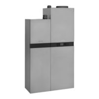
Viessmann C3TB Installation And Service Instructions For Contractors (188 pages)
Micro CHP unit based on a fuel cell with integral gas condensing boiler Natural gas version
Brand:
Viessmann
| Category:
Boiler
| Size: 19 MB
Table of Contents
Index Index
4
Table of Contents
4
Handling
9
Fuel Cell Module
9
Gas Condensing Module
9
Siting
9
Dimensions of Siting Options
10
Preparing for Installation
11
Notes on Connecting to the Mains Supply
14
Vitovalor 300-P in Mains Parallel Mode
14
Metering Generated Power
14
Property Boundaries and Transfer Point Without Power Storage System
16
Property Boundaries and Transfer Point with Power Storage System
17
Connection for Excess Export Without Power Storage System
18
Connection for Excess Export with Power Storage System
19
Cable Sizing
20
Fuse Protection
20
Installing the Vitovalor 300-P
22
Removing the Front Panel of the Gas Condensing Module
22
Connecting the Fuel Cell Module on the Heating Water and Gas Sides
23
Mounting the Diaphragm Expansion Vessel
24
Aligning the Vitovalor 300-P
25
Heating Water and DHW Connections
26
Balanced Flue Terminal
27
Routing Drain Lines
29
Gas Connection
29
Opening the Control Unit Enclosure on the Gas Condensing Module
30
Electrical Connections
31
Vitotronic 200
31
Process Controller
32
Making the Electrical Connection between the Fuel Cell Module and the Gas Condensing Module
34
Outside Temperature Sensor
35
External Demand Via Switching Contact
35
(Hard-Wired)
35
External Demand Via 0
36
External Blocking Via Switching Contact
36
Input
36
Power Supply for Accessories (230 V ~)
37
KM-BUS Connections
38
Connecting Vitocom 300 to LAN
39
Power Supply to the System
39
Installing Wireless Accessories (if Present)
41
Routing the Connecting Cables and Leads
42
Closing the Control Unit Enclosure
42
Closing the Process Controller
43
Fitting the Front Panels
44
If Required for Easier Handling: Dismantling the Gas Condensing Module
45
Commissioning, Inspection, Maintenance Steps - Commissioning, Inspection and Maintenance
50
Steps - Commissioning, Inspection and Maintenance
50
Removing the Front Panels
52
Marking the Type on the Type Plate
52
Checking the Power Supply
52
Overview of Water Circuits
53
Filling the Fuel Cell Module and Heating Water Buffer Cylinder
53
Filling Gas Condensing Module and Heating Circuits
55
Filling the DHW Cylinder
56
Filling the Trap on the Gas Condensing Module with Water
57
Venting the Gas Condensing Module
58
Gas Condensing Module Only: Switching on Mains Power and Control Unit
58
Changing Language Setting (Control Unit, Gas Condensing Module)
59
Setting Time and Date (Control Unit, Gas Condensing Module)
59
Venting the Heating System
59
Registering the External Meter on Vitocom 300 as an M-Bus Subscriber
60
Pairing Wireless Accessories (Where Present)
60
Naming the Heating Circuits
63
Checking the Static Pressure and Supply Pressure
63
Function Sequence and Possible Faults (Gas Condensing Module)
65
Preparing the Fuel Cell Module for Commissioning
66
Changing the Gas Type on the Fuel Cell Module
68
Adjusting Country Settings for Grid Monitoring on the Fuel Cell Module
69
Commissioning the Fuel Cell Module
69
Activating Start Time Optimisation
73
Ending Commissioning Mode - Switching to Standard Mode
73
Linking the Fuel Cell Module and Other Subscribers in LON
73
Setting the Max. Heating Output (Gas Condensing Module)
74
Tightness Test of Balanced Flue System (Annular Gap Test)
75
Starting Service Mode
75
Removing the Burner (Gas Condensing Module)
76
Checking the Burner Gasket and Burner Gauze Assembly (Gas Condensing Module)
77
Checking the Back Draught Safety Device
78
Checking and Adjusting Ignition and Ionisation Electrode (Gas Condensing Module)
78
Cleaning Heating Surfaces (Gas Condensing Module)
78
Checking Condensate Drain and Cleaning the Trap (Gas Condensing Module)
79
Fitting the Burner (Gas Condensing Module)
80
Checking the Neutralising System (if Installed)
80
Cleaning the Air Intake on the Fuel Cell Module
81
Yearly Maintenance of Fuel Cell Module
81
Yearly Maintenance of Fuel Cell Module
86
Checking the External Diaphragm Expansion Vessel (Heating Circuit) and System Pressure
86
Checking the Safety Valve Function
86
Checking the Firm Seating of Electrical Connections
86
Checking for Tightness the Gas-Bearing Parts of the Gas Condensing Module and Connections to the Fuel Cell Module under Operating Pressure
87
Checking the Combustion Quality
87
Checking the Flue System for Unrestricted Flow and Tightness
88
Matching the Control Unit to the Heating System
88
Adjusting the Heating Curves
88
Calling up and Resetting "Service" on the Programming Unit of the Gas Condensing Module
90
Mounting the Cover Panel and Front Panel (Fuel Cell Module)
90
Instructing the System User
91
Codes Coding Level 1
92
Calling up Coding Level 1
92
General
92
Boiler
93
Dhw
94
Heating Circuit
94
Coding Level 2
98
Calling up Coding Level 2
98
General
98
Boiler
103
Dhw
103
Heating Circuit
105
Diagnosis and Service Gas Condensing Module
110
Scans Service Menu
110
Diagnosis
111
Checking Outputs (Actuator Test)
112
Fuel Cell Module
113
Calling up Power Generated
113
Calling up Operating Condition
113
Calling up Grid Monitoring Parameters
113
Resetting Fuel Cell Module Data
114
Fault Codes for Gas Condensing Module
115
Troubleshooting Fault Display on Gas Condensing Module
115
Fault Display, Fuel Cell Module
122
Fault Messages
123
Repairs (Gas Condensing Module)
123
Putting the Control Unit into the Service Position
123
Draining the System on the Heating Water and DHW Sides
123
Checking the Outside Temperature Sensor
126
Checking the Boiler Water Temperature Sensor, Cylinder Temperature Sensor or Flow Temperature Sensor of Low Loss Header
127
Checking the Outlet Temperature Sensor
128
Checking the Return Temperature Sensor
129
Checking the Buffer Temperature Sensor
130
Checking the Plate Heat Exchanger
130
Checking the Flue Gas Temperature Sensor
131
Checking the Temperature Limiter
133
Checking the Fuse/Mcb
134
Mixer Extension Kit
134
Checking the Vitotronic 200-H (Accessories)
135
Parts Lists Overview of Assemblies
137
Casing Assembly
138
Heat Cell Assembly
140
Burner Assembly
144
Heat Cell Hydraulic Assembly
146
External Connection Assembly
148
Buffer Cylinder Assembly
150
DHW Cylinder Assembly
152
Miscellaneous Assembly
154
Vitovalor VBC 132 Control Unit Assembly
156
Vitovalor VUC 170 Control Unit Assembly
158
Fuel Cell Assembly
160
Function Description Control Unit
164
Heating Mode
164
Heating the DHW Loading Cylinder from Cold
164
Operating the Fuel Cell Module
164
Reheating When DHW Is Drawn off
164
Boosting DHW Heating
165
Internal H1 Extension (Standard Delivery)
165
Internal H2 Extension (Accessories)
166
External Extensions (Accessories)
167
AM1 Extension
167
EA1 Extension
168
Control Functions
169
External Operating Program Changeover
169
External Blocking
170
External Demand
170
Venting Program
171
Fill Program
171
Screed Drying
171
Raising the Reduced Room Temperature
173
Reducing the Heat-Up Time
174
Assigning Heating Circuits to the Remote Control
175
Electronic Control Unit on the Peak Load Boiler
176
Connection and Wiring Dia-Connection Diagram, Internal (Gas Condensing Module)
177
Gram Connection Diagram, External (Gas Condensing Module)
178
Differential Temperature Controller
179
Commissioning/Service
180
Specification
181
Disposal Final Decommissioning and Disposal
182
Certificates Declaration of Conformity
183
Manufacturer's Certificate According to the 1St Bimschv [Germany]
183
Keyword Index
184
Advertisement
Advertisement
Related Products
Viessmann C33
Viessmann C3HA
Viessmann CT3-72
Viessmann CM2-400
Viessmann CM2-620
Viessmann C83
Viessmann CVA
Viessmann C93
Viessmann CM2-500
Viessmann CT3-37
Viessmann Categories
Boiler
Toy
Control Unit
Heat Pump
Solar panel
More Viessmann Manuals
Login
Sign In
OR
Sign in with Facebook
Sign in with Google
Upload manual
Upload from disk
Upload from URL