Sign In
Upload
Manuals
Brands
VIA Technologies Manuals
Control Unit
STK-SOM6X80-00A1
VIA Technologies STK-SOM6X80-00A1 Manuals
Manuals and User Guides for VIA Technologies STK-SOM6X80-00A1. We have
1
VIA Technologies STK-SOM6X80-00A1 manual available for free PDF download: User Manual
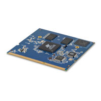
VIA Technologies STK-SOM6X80-00A1 User Manual (38 pages)
Ultra-compact low-power solution for HMI applications with rapid time-to-market
Brand:
VIA Technologies
| Category:
Computer Hardware
| Size: 6 MB
Table of Contents
Table of Contents
5
1 Product Overview
8
Key Features
8
Product Specifications
9
Layout Diagram
11
Figure 1: Layout Diagram of the SOM-6X80 Module (Top Side)
11
Figure 2: Layout Diagram Of The Som-6X80 Module (Bottom Side)
11
Product Dimensions
12
Figure 3: Dimensions of the SOM-6X80 Module (Top View)
12
Figure 4: Dimensions of the SOMDB1 Carrier Board with the SOM-6X80 Module Installed
12
2 Onboard I/O Connector
13
Debug Connector
13
Figure 5: Debug Connector Diagram
13
Table 1: Debug Connector Pinouts
13
3 Hardware Installation
14
Installing the SOM-6X80 Module on the SOMDB1 Carrier Board
14
Figure 6: Installing the SOM-6X80 Module
14
Figure 7: Securing the SOM-6X80 Module
14
4 Software And Technical Support
15
Linux Support
15
Technical Support and Assistance
15
Appendix A. SOMDB1 Carrier Board Reference
16
Board Specifications
16
SOMDB1 Layout Diagram
17
Figure 8: Layout Diagram Of The Somdb1 Connectors, Slot, Buttons, Switch (Top Side)
17
Figure 9: Layout Diagram of the SOMDB1 Pin Headers (Top Side)
17
Figure 10: SOMDB1 Front Panel I/O
18
Figure 11: SOMDB1 Back Panel I/O
18
Figure 12: SOMDB1 Right Panel I/O
18
SOMDB1 Onboard I/O
19
LCD Panel Connector
19
Figure 13: LCD Panel Connector Diagram
19
Table 2: LCD Panel Connector Pinouts
19
Touch Connector
20
Figure 14: Touch Connector Diagram
20
Table 3: Touch Connector Pinouts
20
A.2.1.2. Touch Connector
20
USB 2.0 Connector
21
Camera Connector
21
Figure 15: USB 2.0 Connector Diagram
21
Figure 16: Camera Connector Diagram
21
Table 4: USB 2.0 Connectors Pinouts
21
Table 5: Camera Connector Pinouts
21
COM Connector and UART Pin Header
22
Figure 17: COM Connectors and UART Pin Headers Diagram
22
Table 6: COM Connectors Pinouts
22
Table 7: UART Pin Headers Pinouts
22
GPIO Pin Header
23
SPI Pin Header
23
Figure 18: GPIO Pin Header Diagram
23
Figure 19: SPI Pin Header Diagram
23
Table 8: GPIO Pin Header Pinouts
23
Table 9: SPI Pin Header Pinouts
23
C Pin Header
24
Headphone Pin Header
24
Figure 20: I C Pin Header Diagram
24
Figure 21: Headphone Pin Header Diagram
24
Table 10: I 2 C Pin Header Pinouts
24
Table 11: Headphone Pin Header Pinouts
24
MIC-In Connector
25
Mono Speaker out Connector & Pin Header
25
Figure 22: MIC-In Connector Diagram
25
Figure 23: Mono Speaker out Connector & Pin Header Diagram
25
Table 12: MIC-In Connector Pinouts
25
Table 13: Mono Speaker out Connector & Pin Header Pinouts
25
Audio Mono out Signal Pin Header
26
Left Channel Speaker Connector & Pin Header
26
Figure 24: Audio Mono out Signal Pin Header Diagram
26
Figure 25: Left Channel Speaker Connector & Pin Header Diagram
26
Table 14: Audio Mono out Signal Pin Header Pinouts
26
Table 15: Left Channel Speaker Connector & Pin Header Pinouts
26
Right Channel Speaker Connector & Pin Header
27
Line-In Pin Header
27
Figure 26: Right Channel Speaker Connector & Pin Header Diagram
27
Figure 27: Line-In Pin Headers Diagram
27
Table 16: Right Channel Speaker Connector & Pin Header Pinouts
27
Table 17: Line-In Pin Headers Pinouts
27
IR Receiver Sensor & Pin Header
28
Debug Connector & Pin Header
28
Figure 28: IR Receiver Sensor & Pin Header Diagram
28
Figure 29: Debug Connector & Pin Header Diagram
28
Table 18: IR Receiver Sensor & Pin Header Pinouts
28
Table 19: Debug Connector & Pin Header Pinouts
28
Power Button
29
System Recovery Button
29
Watchdog Timer Switch
29
Figure 30: Power Button Diagram
29
Figure 31: System Recovery Button Diagram
29
Figure 32: Watchdog Timer Switch Diagram
29
RCA Pin Header
30
Rtc Battery Connector
30
Figure 33: Rtc Battery Connector Diagram
30
Figure 34: RCA Pin Header Diagram
30
Figure 35: Rtc Battery Connector Diagram
30
Table 20: RCA Pin Header Pinouts
30
DC-In Connector
31
Figure 36: DC-In Connector Diagram
31
Table 21: DC-In Connector Pinouts
31
SOM DDR3 SODIMM Slot
32
Figure 37: SOM DDR3 SODIMM Slot Diagram
32
Table 22: SOM DDR3 SODIMM Slot Pinouts
33
SOMDB1 External I/O
34
HDMI ® Port
34
Micro USB 2.0 OTG Port
34
Figure 38: HDMI Port Diagram
34
Figure 39: Micro USB 2.0 OTG Port Diagram
34
Table 23: HDMI Port Pinouts
34
Table 24: Micro USB 2.0 OTG Port Pinouts
34
10/100Mbps Ethernet Port
35
Headphone Jack
35
Figure 40: 10/100Mbps Ethernet Port Diagram
35
Figure 41: Headphone Jack Diagram
35
Table 25: 10/100Mbps Ethernet Port Pinouts
35
Table 26: 10/100Mbps Ethernet Port Led Color Definition
35
Micro SD Card Slot
36
RCA Jack
36
Figure 42: Micro SD Card Slot Diagram
36
Figure 43: RCA Jack Diagram
36
Table 27: Micro SD Card Slot Pinouts
36
SOMDB1 Dimensions
37
Figure 44: Dimensions of the SOMDB1 Carrier Board
37
Figure 45: Dimensions of the SOMDB1 Front Panel I/O
37
Figure 46: Dimensions of the SOMDB1 Back Panel I/O
37
Figure 47: Dimensions of the SOMDB1 Right Panel I/O
37
A.3. SOMDB1 Dimensions
37
Advertisement
Advertisement
Related Products
VIA Technologies SOM-3000-STK
VIA Technologies SOM-9X50
VIA Technologies STK-VT6093-00A1
VIA Technologies STK-VT6093-01A1
VIA Technologies STK-SOM500-00A0
VIA Technologies EPIA SP 13000
VIA Technologies SOM-6X80
VIA Technologies SOM-6X50
VIA Technologies SOM-9X50-STK
VIA Technologies SOM-9X35-STK
VIA Technologies Categories
Motherboard
Computer Hardware
Desktop
Control Unit
Industrial PC
More VIA Technologies Manuals
Login
Sign In
OR
Sign in with Facebook
Sign in with Google
Upload manual
Upload from disk
Upload from URL