Sign In
Upload
Manuals
Brands
VersaLogic Manuals
Control Unit
STD32 VL-1225
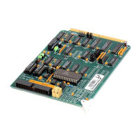
VersaLogic STD32 VL-1225 Input Board Manuals
Manuals and User Guides for VersaLogic STD32 VL-1225 Input Board. We have
1
VersaLogic STD32 VL-1225 Input Board manual available for free PDF download: Reference Manual
VersaLogic STD32 VL-1225 Reference Manual (80 pages)
Analog Input/Output Cards for the STD Bus
Brand:
VersaLogic
| Category:
Control Unit
| Size: 3 MB
Table of Contents
Table of Contents
4
Overview
6
Introduction
6
Features
6
Specifications
7
Configuration
8
Jumper Options
8
VL-1225 Jumper Block Locations
9
VL-1225 Jumper Options
10
VL-1226 Jumper Block Locations
11
VL-1226 Jumper Options
12
Board Addressing
13
8-Bit I/O Addressing
14
10-Bit I/O Addressing
15
16-Bit I/O Addressing
16
IOEXP Signal
17
16-Bit Memory Addressing
18
MEMEX Signal
19
Analog Input Configuration
20
Input Mode
20
Single Ended Mode
20
Pseudo-Differential Mode
21
Differential Mode
21
Current Loop Mode
22
Input Voltage Range
23
Input Resolution
23
Input Data Format
24
Analog Output Configuration
25
Output Voltage Range
25
Output Data Format
26
Output Power-Up Voltage
27
Interrupt Configuration
28
Installation
30
Handling
30
Priority Chain
30
Signal Levels
30
External Connections
31
Mating Connectors
31
Physical Pin Locations
31
Connector Pinout
32
Registers
34
Introduction
34
Register Mapping
34
Analog Input Registers
35
Input Channel Select Register
35
Input Data Low Register
36
Input Data High Register
36
Input Data Representation
37
Input Binary Format (10-Bit Resolution)
37
Input Binary Format (11-Bit Resolution)
38
Input Offset Binary Format (10-Bit Resolution)
39
Input Offset Binary Format (11-Bit Resolution)
40
Input Two's Complement Format (10-Bit Resolution)
41
Input Two's Complement Format (11-Bit Resolution)
42
Analog Output Registers
43
Output Data Registers
43
Output Data Representation
43
Output Binary Format
43
Output Offset Binary Format
44
Output Two's Complement Format
45
Interrupt Registers
46
Interrupt Control Register
46
Interrupt Status Register
46
Operation
48
Polled Mode Analog Input
48
Interrupt Mode Analog Input
49
Analog Output
49
Software Examples
50
Polled Mode Analog Input
50
Interrupt Mode Analog Input
51
Analog Output
54
Reference
56
Specifications
56
VL-1225 Jumper Block Locations
57
VL-1226 Jumper Block Locations
59
Register Map
61
Calibration
62
Input Calibration (VL-1225 and VL-1226)
62
Output Calibration (VL-1225 Only)
63
External Connections
63
Mating Connectors
63
Physical Pin Locations
64
Connector Pinout
64
Decimal / Hex / ASCII Conversion Chart
65
STD 80 Bus Pinout
66
STD 32 Bus Pinout Extension
67
VL-1225 Parts Placement Diagram
68
VL-1225 Schematic
69
VL-1225 Parts List
72
VL-1226 Parts Placement Diagram
74
VL-1226 Schematic
75
VL-1226 Parts List
78
Advertisement
Advertisement
Related Products
VersaLogic STD32 VL-1226
Versalogic SandCat
VersaLogic SPX-2
VersaLogic SPX-5
VersaLogic VL-EPHs-P1
VersaLogic VL-EPM-E2
VersaLogic VL-EPM-E2A
VersaLogic VL-EPM-E2B
VersaLogic VL-EPM-E2D
VersaLogic VL-MPEE-V5E
VersaLogic Categories
Motherboard
Single board computers
Computer Hardware
Control Unit
Desktop
More VersaLogic Manuals
Login
Sign In
OR
Sign in with Facebook
Sign in with Google
Upload manual
Upload from disk
Upload from URL