Sign In
Upload
Manuals
Brands
VersaLogic Manuals
Server Board
Grizzly
VersaLogic Grizzly Manuals
Manuals and User Guides for VersaLogic Grizzly. We have
2
VersaLogic Grizzly manuals available for free PDF download: Hardware Reference Manual, User Manual
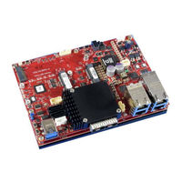
VersaLogic Grizzly Hardware Reference Manual (48 pages)
A rugged embedded server unit featuring the Intel C3958 16-core micro-server processor and 10 GbE networking ports
Brand:
VersaLogic
| Category:
Server Board
| Size: 3 MB
Table of Contents
Table of Contents
5
Introduction
8
Description
8
Technical Specifications
10
VL-ESU-5070 Block Diagram
10
VL-ESU-5070 MCU Block Diagram
11
Warnings
12
Electrostatic Discharge
12
Handling Care
12
Earth Ground Requirement
12
Configuration and Setup
13
Initial Configuration
13
Basic Setup
13
Operating System Installation
15
Physical Details
16
Dimensions and Mounting
16
Figure 1. VL-ESU-5070 Dimensions and Mounting Holes
16
External Connectors
17
VL-ESU-5070 Connector Locations - Top
17
Figure 2. VL-ESU-5070 Connector Locations - Top
17
ESU-5070 Connector Functions and Interface Cables
18
Table 1. Connector Functions and Interface Cables
18
VL-CBR-2005 Connector Locations
19
VL-CBR-2005 Connector Functions
19
Jumper Blocks
19
Jumpers As-Shipped Configuration
19
Table 2. VL-CBR-2005 Connector Functions
19
Figure 3. VL-CBR-2005 Connectors
19
Figure 4. Jumper Block Locations
19
Table 3. Jumper Summary
20
System Features
21
Power Supply
21
Power Connector
21
Power Requirements
21
Power Delivery Considerations
21
Table 4. Main Power Connector Pinout (J6)
21
Figure 5. Power Connector Orientation and Pinout
21
Cpu
22
System RAM
22
Note: the Intel C3958 Processor Supports X8 or X16 Width for Unbuffered Memory SO-DIMM. Microcontroller
22
Board Management
22
Intelligent Platform Management Interface (IPMI)
23
Expansion Busses
23
Ethernet
23
Usb
23
Serial I/O
23
Digital I/O
23
Mini Pcie
24
Interfaces and Connectors
25
Video Interfaces
25
Ethernet
25
Ethernet Connectors
25
Table 5. 1000Base-T, 100Base-TX, and 10Base-T Ethernet Connector Pinouts
25
Ethernet Connectors (Poe)
26
Table 6. 1000Base-T, 100Base-TX, and 10Base-T Ethernet Connector Pinouts (Poe)
26
Table 7. Poe Power Signals (J7)
26
Figure 6. Poe Power Connector Pinout and Orientation
26
10Gbe Ethernet
27
Ethernet Software Defined Pins (SDP)
27
Table 8. 10 Gbe Ethernet Connector Pinouts (J17, J21)
27
Serial Ports
28
USB Interfaces
28
Table 9. COM Port Signals
28
Table 10. USB Port Pinouts
28
Mini Pcie Cards
29
Table 11. Pcie Full-Size Minicard #1 Pinouts (J12)
29
Table 12. Pcie Half-Size Minicard #2 Pinouts (J13)
30
Minicard Leds
31
Table 13. Minicard #1 and #2 LED Indicators
31
Table 14. M.2 Pinouts (J23)
31
Status Leds
33
SATA Ports
33
Table 15. On-Board M.2 Status Leds
33
Table 16. SATA Pinouts (J1 and J28)
33
Table 17. SATA Power Signals (J31)
33
SATA and SFP Status LEDS (J5)
34
Table 18. SATA and SFP Status LEDS
34
CBR-2005 Paddleboard
35
CBR-2005 Connectors
35
Table 19. ESU-5070 J2 and CBR-2005 J5 Connector Pinout
35
Figure 7. J4/J3/J2/J1 Digital I/O Terminal Block Pinouts
35
Dimensions and Mounting Holes
36
Figure 8. CBR-2005 Dimensions and Mounting Holes
36
Thermal Characterization
37
Selecting the Correct Thermal Solution for Your Application
37
Heat-Plate
37
System-Level Considerations
37
CPU Thermal Trip Points
38
Table 20. CPU Thermal Trip Points
38
Thermal Specifications, Restrictions, and Conditions
39
Overall Restrictions and Conditions
39
Heat-Plate Only Restrictions and Conditions
39
Heat-Sink with Fan Considerations
39
Heat-Pipe Considerations
39
Table 21. Absolute Minimum and Maximum Air Temperatures
39
Thermal Characterization
40
Test Results
40
Table 22. Product Thermal Testing Setup
40
Table 23. Heat-Sink Configuration 1
40
Table 24. Heat-Sink Configuration 2
40
Installing ESU-5070 Thermal Solutions
41
Figure 9. ESU-5070 Heat Spreader
41
Figure 10. Removing the ESU-5070 Top DIMM Cover
42
Figure 11. HDW-421 - Installing the Fan-Sink Thermal Accessory (Bottom)
43
Installing the HDW-421 Heat-Sink and Fan
43
Figure 12. HDW-421 - Installing the Fan-Sink Thermal Accessory (Top)
45
Figure 13. HDW-422 - Installed Fan Heat-Sink Thermal Accessory
45
Figure 14. Installing the HDW-422 Heat-Pipe Thermal Assembly (Top)
46
Installing the HDW-422 Heat-Pipe Thermal Assembly
46
Notes
46
Figure 15. Installing the HDW-422 Heat-Pipe Thermal Assembly (Bottom)
47
Figure 16. HDW-422 - Installed Heat-Pipe Thermal Accessory
48
Advertisement
VersaLogic Grizzly User Manual (30 pages)
A rugged embedded server unit featuring the Intel® C3958 16-core micro-server processor and 10 GbE networking ports.
Brand:
VersaLogic
| Category:
Server
| Size: 0 MB
Table of Contents
Table of Contents
5
Introduction
7
Description
7
Configuration and Setup
9
Initial Configuration
9
Basic Setup
9
Operating System Installation
10
Remote Management Summary
11
Block Diagram
12
Figure 1. ESU-5070 Remote Management Configuration
12
Remote Management Configuration
13
Figure 2. Out-Of-Band Configuration Port
13
Ipmitool
14
Accessing the MCU Management Controller
15
Using Serial over LAN
15
IPMI Commands Supported by IE
16
Global
16
Ipmitool Examples
16
Chassis
16
Ipmitool Examples
17
Watchdog Timer
17
Device and Messaging
17
Event
18
Ipmitool Examples
18
PEF and Alerting
19
Fru
19
MCU FRU Data
19
Ipmitool Examples
19
IE FRU Data
20
Ipmitool Examples
20
Sel
20
Ipmitool Examples
21
Sensor
21
Sdr
21
Ipmitool Examples
22
Lan
22
Serial
22
IPMI Commands Supported by MCU
23
Global
23
Event
23
Fru
23
Sensor
23
Sdr
23
Sensor Type Details
24
IE Sensor
24
MCU Sensor (-T 0X4E)
26
Advertisement
Related Products
VersaLogic VL-ESU-5070
VersaLogic Categories
Motherboard
Single board computers
Computer Hardware
Control Unit
PCI Card
More VersaLogic Manuals
Login
Sign In
OR
Sign in with Facebook
Sign in with Google
Upload manual
Upload from disk
Upload from URL