Sign In
Upload
Manuals
Brands
VDO Manuals
Measuring Instruments
CANcockpit Series
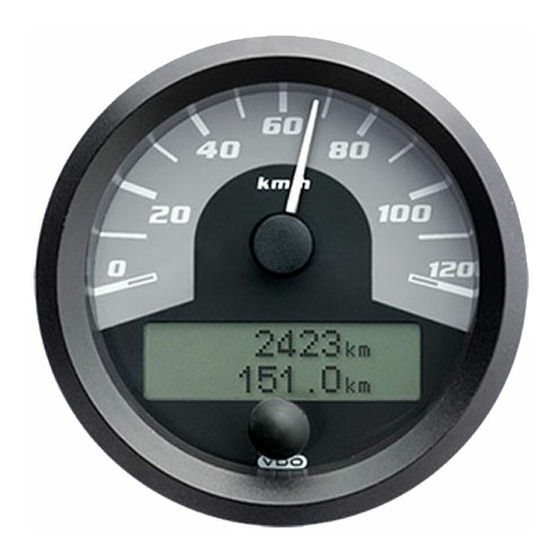
VDO CANcockpit Series Manuals
Manuals and User Guides for VDO CANcockpit Series. We have
1
VDO CANcockpit Series manual available for free PDF download: Product Manual
VDO CANcockpit Series Product Manual (175 pages)
New Generation 2009 Flexible instrumentation with CAN bus technology
Brand:
VDO
| Category:
Measuring Instruments
| Size: 7.76 MB
Table of Contents
Table of Contents
3
Contents
4
Before Installation
4
Safety Instructions
4
After Installation
5
During Installation
5
Electrical Connection
6
Pressure Sensor for Oil
7
Temperature Sensor for Oil
8
Temperature Sensor for Engine Coolant
9
Fuel Level Sensor (Lever Type Sensor/Tubular Type Sensor)
10
Functional Specification
11
Contents
13
System
13
Main Features
13
Block Diagram Cancockpit
13
Mechanical Concept
13
Safety Concept
14
System Check
14
Satbus
14
Wingauge
14
Sensors
14
Master Gauges
15
General Features
15
Main Functions
15
Master Dia. 80 MM
16
Master Dia. 85 MM
16
Master Dia. 100 MM
16
Mechanical Concept
16
Analog Inputs
17
Grounding Concept
17
Input Signal Processing Applied to the Two Frequency Inputs
17
Sensors
17
Input Signal Processing for Canbus Messages
18
PIN Assignment Description
19
Technical Description
19
PIN 2: Ground (Terminal 31)
19
PIN 3, 4: Canbus Interface 1
19
PIN 14: +8 V Sensor Power Supply
20
PIN 15: 0 - 5 V Input
20
PIN 17: Ignition (Terminal 15)
20
Display Functions
22
Navigation through Display
22
Display Layout
22
Dot Matrix Layout
23
Symbol Area
23
Central Area
23
Physical Unit Area
23
Main Display (Odometer, Hourmeter)
24
Alarm Display
24
Configuration Option
24
Display Functions
24
CAN DTC Display
25
Warning Display
25
Service Message
26
Physical Value Display
26
Alarm- and Warning Functions
27
Description of the Outputs
27
Switch Output Acknowledgement Function
27
Alarm and Warning Trigger Conditions
28
Alarm and Warning Trigger Enabling with Engine Running
28
Alarm and Warning State Diagram (Maximum Value Algorithm)
30
Service
31
Reset of Service Messages
31
Procedure for Resetting a Service Message
31
CAN (SAE J1939) DTC (Diagnostic Trouble Codes) Messages
32
SPN Conversion Method (CM) 1Bit
32
Failure Mode Indicator (FMI) 5Bits
32
CAN DTC Information Display Requirements
33
CAN DTC Display Functions
33
DTC Reception
33
DTC List
33
DTC List Display Format
34
Diagnostic Lamp Status
35
DTC Scan
35
Speedometer Master Gauge
35
Tolerance
35
Speedometer Gauge Operation
36
Specification of Odometer Storage
36
Information Comes from CAN-Bus Interfaces (One of Two)
36
Total Odometer Information Generated by Master Gauge
36
Tachometer Master Gauge
37
Tachometer Gauge Operation
37
Specification of the Hourmeter
37
Satellite Gauges
38
Fault Modes
38
Satellite Gauge Address
39
Warning Lamp Inside the Satellite Gauge
39
EMC Requirements
40
Ground Shift
40
Overvoltage Protection
40
A. Technical Data
40
B. Applied Standards
41
Enclosures
42
Tu00-0736-0000002
42
System Components
44
Installation Instructions
47
Wiring Harness Master
51
Cable Allocation
51
Gauge Connection
51
Software Description
52
Tu00-0736-0000002
52
Components and Concept
54
Master Gauge
54
Example of a Fully Configured Instrumentation
55
Basic Steps to Build a New Configuration
57
Definition of Project Properties
58
Adding a Master Instrument
59
Adding the Required Satellites
62
Adding the Required Displays
68
ICON Editor
78
Product Information
108
Contents
109
Summary of Features
110
Expressions
110
Hardware Requirements
111
Canopen Baud Rates and Sample Points for Cancockpit
111
Galvanic Isolation
111
Firmware Requirements
111
11Bit Identifiers
111
CAN Interfaces
111
Master or Slave
111
Operational States
112
Initialisation
112
Boot-Up Message
112
Pre-Operational
112
Heartbeat
112
Lifeguarding
112
Stopped
112
States and Communication Objects
112
Error Handling
113
Error Behaviour
113
Emergency Messages
113
Simple J1939 <-> Canopen Gateway
113
Minimum Capabilities
114
Static Allocation of the Communication Object Identifiers (COB-ID's)
114
Restore Defaults
114
Product Manual Cancockpit
115
Device Profile
115
Canopen Text and Icon Display
115
Canopen Display Format with 4X16 Characters (Small Font)
115
Pre-Defined Connection Set
116
COB ID Structure of Pre-Defined Connection Set
116
Object Dictionary
117
Administrative Messages
117
Service Data Messages
117
Process Data Messages
117
Triggering Modes
118
Pre-Defined Messages
118
Entries in Object Directory
118
Communication Profile Area
118
Manufacturer Firmware Version (100Ah)
119
Example of the Format: 31_12_2004
119
COB-ID Emergency Object (1014H)
119
Consumer Heartbeat (1016H)
119
Producer Heartbeat Time (1017H)
120
Identity Object (1018H)
120
Receive PDO Communication Parameters (1400H to 1406H)
121
Receive PDO Mapping Parameters (1600H to 1606H)
122
1St RPDO: 8X8 Digital Outputs:
123
Transmit PDO Communication Parameters (1800H to 1802H)
124
Transmit PDO Mapping Parameter (1A00H to 1A02H)
124
2Nd TPDO: 4 Analogue Inputs
125
3Rd TPDO: 4 Analogue Inputs
125
Canopen Display
125
Write Display Mode (2000H)
125
Manufacturer Specific Profile Area
125
Write Alarm Display Data 2Lines X 8Characters (2001H)
126
Write Warning Display Data 2Lines X 8Characters (2002H)
126
Write Alarm or (but Not And) Warning Display 4X16 (2003H)
127
Trigger Hardware Reset (2004H)
127
Read Data Record from EEPROM
128
Write EEPROM Data Record to EEPROM
129
Standardised Device Profile Area
130
Polarity of 64 Digital Inputs (6002H)
131
Write 64 Digital Outputs Byte Wise (6200H)
133
Change Polarity Output 8-Bit (6202H)
134
Error Mode Output 8-Bit (6206H)
136
Error Value Output 8-Bit (6207H)
137
Read Analogue Inputs Word Wise (6401H)
138
Write Analogue Outputs Word Wise (6411H)
140
Appendix
142
Literature
142
References
142
Tu00-0736-0000002
143
Contents
144
System Components
144
Master Gauges
144
Tu00-0736-0000002
144
Satelitte Gauges
145
Tu00-0736-0000002
145
Master Black Box
146
Tu00-0736-0000002
146
Articel Description
147
Tu00-0736-0000002
147
Clamp Rings
148
Spare Parts and Accessories
148
Tu00-0736-0000002
148
Accessories
149
Wiring Harnesses
149
Tu00-0736-0000002
149
Parts for Own Installation of the Wiring Harnesses
150
Tu00-0736-0000002
150
Software Accessories
151
Demo Case
151
Tu00-0736-0000002
151
Cancockpit
152
Advertisement
Advertisement
Related Products
VDO CONTISYS OBD -
VDO CD 2203 -
VDO CD 2604 MP3 -
VDO CDR 2005
VDO CD 139 MP3
VDO CD716U-BU
VDO CD 5304 MP3
VDO CHD 1002 S
VDO CD 2537 U
VDO CR 2151
VDO Categories
Car Receiver
Bicycle Accessories
Automobile Electronics
Measuring Instruments
Automobile Accessories
More VDO Manuals
Login
Sign In
OR
Sign in with Facebook
Sign in with Google
Upload manual
Upload from disk
Upload from URL