Sign In
Upload
Manuals
Brands
Vanguard Instruments Manuals
Test Equipment
EZCT-2000C
Vanguard Instruments EZCT-2000C Manuals
Manuals and User Guides for Vanguard Instruments EZCT-2000C. We have
1
Vanguard Instruments EZCT-2000C manual available for free PDF download: User Manual
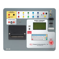
Vanguard Instruments EZCT-2000C User Manual (119 pages)
DIGITAL CURRENT-TRANSFORMER TESTER
Brand:
Vanguard Instruments
| Category:
Test Equipment
| Size: 5 MB
Table of Contents
Table of Contents
3
Conventions Used in this Document
5
1 Introduction
6
General Description and Features
6
Common Features (EZCT-2000C and EZCT-2000C Plus)
6
EZCT-2000C Plus Features
8
Ordering Information
9
Table 1. Ordering Information
9
Technical Specifications
10
Table 2. EZCT-2000C Technical Specifications
10
EZCT-2000C Controls and Indicators
11
Figure 1. EZCT-2000C Controls and Indicators
11
Table 3. Functional Descriptions of EZCT-2000C Controls and Indicators
12
2 Pre-Test Setup
13
Operating Voltages
13
LCD Screen Contrast Control
13
Printer Paper Control
13
Printer Paper
13
3 Operating Procedures
15
EZCT-2000C Cable Connections
15
Figure 2. Typical EZCT-2000C Excitation and Ratio Test Cable Connections
15
Figure 3. Connections for a Typical High Resistance Measuring Application
16
Figure 4. Connections for a Typical Insulation Resistance Measurement for a CT with 5 Terminals
16
Figure 5. Connections for a Typical Insulation Resistance Measurement for a CT with 2 Terminals
17
Figure 6. EZCT-2000C CT Burden Test Cable Connection (EZCT-2000C Plus Only)
18
Figure 7. EZCT-2000C Typical Current Source Connection (EZCT-2000C Plus Only)
19
Figure 8. Bushing CT Connection on Delta Transformer
20
Figure 9. Bushing CT Connection on y Transformer
20
EZCT-2000C X Input Voltage Warning
21
Figure 10. Sample CT Name Plate
21
Performing Tests
22
Entering Test Record Header Information
22
Performing Resistance, Excitation, and Ratio Tests
25
Figure 11. Typical EZCT-2000C Tabulated Report Printout
33
Table 4. Descriptions of Tabulated Test Results Elements
34
Figure 12. Typical EZCT-2000C Graphic Report with Multiple Plot Curves
35
Performing a CT Burden Test (EZCT-2000C Plus Only)
36
Figure 13. EZCT-2000C Typical Burden Test Results Report Printout
40
Performing an Insulation Resistance Test
41
Figure 14. Connections for a Typical High Resistance Measuring Application
41
Figure 15. Connections for a Typical Insulation Resistance Measurement for a CT with 5 Terminals
41
Figure 16. Connections for a Typical Insulation Resistance Measurement for a CT with 2 Terminals
41
Figure 17. EZCT-2000C Typical Insulation Resistance Test Results Report Printout
45
Performing a Current Source Test (EZCT-2000C Plus Only)
46
Working with Test Records
48
Restoring and Printing a Test Record from Flash EEPROM
48
Restoring and Printing a Test Record from a USB Flash Drive
52
Printing a Restored Test Record
54
Printing a Directory of Test Records Stored in the EZCT-2000C's Memory
56
Figure 18. Typical Internal Test Record Directory Printout
58
Printing a Directory of Test Records Stored in a USB Flash Drive
59
Figure 19. Typical USB Flash Drive Record Directory Printout
60
Copying Test Records to a USB Flash Drive
61
Erasing Test Records from the Flash EEPROM
64
Erasing Test Records from a USB Flash Drive
67
Working with Test Plans
70
Extracting the Test Plan from a Test Record
70
Printing a Directory of Test Plans Stored in the EZCT-2000C's Memory
72
Figure 20. Typical EZCT-2000C Flash EEPROM Test Plan Directory Printout
73
Printing a Directory of Test Plans Stored in a USB Flash Drive
74
Figure 21. Typical USB Flash Drive Test Plan Directory Printout
75
Printing a Test Plan
76
Table 5. Description of Test Plan Elements
77
Figure 22. Typical Test Plan Printout
77
Erasing Test Plans from the Flash EEPROM
78
Erasing Test Plans from a USB Flash Drive
81
Loading a Test Plan from the EZCT-2000C's Flash EEPROM
84
Loading a Test Plan from a USB Flash Drive
86
Running a Test Using a Loaded Test Plan
88
Unloading a Test Plan from the Working Memory
92
4 Changing Setup Parameters
93
Setting the Knee Point Marker
93
Figure 23. Graphic Report Showing Knee Point Marker
94
Enabling and Disabling the Buried CT in Transformer Delta Option
95
Enabling the Buried CT in Transformer Delta Option
95
Disabling the Buried CT in Transformer Delta Option
96
Figure 24. Buried CT in a Delta Transformer Illustration 1
98
Figure 25. Buried CT in a Delta Transformer Illustration 2
98
Setting the Clock
100
Setting the Preferred Interface Language
101
Printing Raw Memory Buffer Data
103
Disabling the H Voltage Checking Feature
104
5 Diagnostics, Verification, and Troubleshooting
106
Performing a Diagnostics Test
106
Verifying the EZCT-2000C's
108
Sense Circuit Using an External Meter
108
Figure 26. EZCT-2000C V X Verification Test Connections
108
Verifying the EZCT-2000C's I X Sense Circuit Using an External Meter
109
Figure 27. EZCT-2000C I Verification Test Connections
109
Quickly Verifying the EZCT-2000C's Turns Ratio Circuit
110
Figure 28. EZCT-2000C Turns Ratio Verification Test Connections
110
Troubleshooting Guide
111
6 Appendix A - Calculating Turns Ratio on a Shunt Reactor
112
Figure 29
112
Figure 30
113
Figure 31
114
Figure 32
115
Figure 33
116
Figure 35
118
Figure 36
118
Advertisement
Advertisement
Related Products
Vanguard Instruments EZCT
Vanguard Instruments EZCT-10
Vanguard Instruments EZCT-2000A
Vanguard Instruments CVT-765
Vanguard Instruments EZCT S2
Vanguard Instruments EZCT S2A
Vanguard Instruments MCCB-500
Vanguard Instruments RFD-200 2 Series
Vanguard Instruments VBT-75
Vanguard Instruments VBT-75 S2
Vanguard Instruments Categories
Measuring Instruments
Test Equipment
Power Supply
Adapter
Timer
More Vanguard Instruments Manuals
Login
Sign In
OR
Sign in with Facebook
Sign in with Google
Upload manual
Upload from disk
Upload from URL