Sign In
Upload
Manuals
Brands
Vaisala Manuals
Transmitter
HMT370EX
Vaisala HMT370EX Manuals
Manuals and User Guides for Vaisala HMT370EX. We have
1
Vaisala HMT370EX manual available for free PDF download: User Manual
Vaisala HMT370EX User Manual (152 pages)
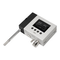
Intrinsically Safe Humidity and Temperature Transmitter Series
Brand:
Vaisala
| Category:
Transmitter
| Size: 5 MB
Table of Contents
Table of Contents
3
About this Document
11
Version Information
11
Related Manuals
11
Table 2 Related Manuals
11
Documentation Conventions
12
Trademarks
12
Product Overview
13
Introduction to HMT370EX Series
13
Basic Features and Options
13
Hazardous Area Safety
13
Available Measurement Parameters
14
Table 3 Available Measurement Parameters for HMP371
14
Table 4 Available Measurement Parameters for HMP378F and HMP378H
14
Display Options
16
LED States in Transmitter with no Display
16
Figure HMT370EX Transmitter Display Options
16
Connectivity to Vaisala Insight Software
17
Table 5 LED Status Indicator States
17
Transmitter Parts
18
Figure 2 HMT370EX Transmitter External Parts
18
Cable Gland and Conduit Options
19
Figure 3 HMT370EX Transmitter Internal Parts
19
Figure 4 Default Plugs in HMT370EX Lead-Throughs
20
Table 6 Cable Lead-Through Accessories
20
HMT370EX Regional Safety Certification Information
21
Regional Safety Certification Overview
21
Table 7 HMT370EX Series Regional Ex Classifications
21
Atex/Iecex Safety Certification Information
22
Using HMT370EX Series Transmitters in Hazardous Locations
22
Table 8 HMT370EX Series Hazardous Area Classifications
23
Guidelines for Safe Use in Hazardous Conditions
24
Figure 5 HMT370EX Parts Overview
24
Table 9 Allowed Ambient Temperature Ranges
25
Table 10 Intrinsically Safe Input Parameters
26
Figure 6 Location of Test Points and Service Port
27
Japan Safety Certification Information
28
Using HMT370EX Series Transmitters in Hazardous Locations
28
Table 11 HMT370EX Series Hazardous Area Classifications
29
Guidelines for Safe Use in Hazardous Conditions
30
Figure 7 HMT370EX Parts Overview
30
Table 12 Allowed Ambient Temperature Ranges
31
Table 13 Intrinsically Safe Input Parameters
32
Figure 8 Location of Test Points and Service Port
33
China Safety Certification Information
34
Using HMT370EX Series Transmitters in Hazardous Locations
34
Table 14 HMT370EX Series Hazardous Area Classifications
35
Guidelines for Safe Use in Hazardous Conditions
36
Figure 9 HMT370EX Parts Overview
36
Table 15 Allowed Ambient Temperature Ranges
36
Table 16 Intrinsically Safe Input Parameters
38
Figure 10 Location of Test Points and Service Port
39
Korea Safety Certification Information
40
Using HMT370EX Series Transmitters in Hazardous Locations
40
Table 17 HMT370EX Series Hazardous Area Classifications
41
Guidelines for Safe Use in Hazardous Conditions
42
Figure 11 HMT370EX Parts Overview
42
Table 18 Allowed Ambient Temperature Ranges
42
Figure 12 Location of Test Points and Service Port
44
Table 19 Intrinsically Safe Input Parameters
44
FM) Safety Certification Information
45
Using HMT370EX Series Transmitters in Hazardous Locations
45
Table 20 HMT370EX Series Hazardous Area Classifications
46
Guidelines for Safe Use in Hazardous Conditions
47
Figure 13 HMT370EX Parts Overview
47
Table 21 Allowed Ambient Temperature Ranges
48
Table 22 Intrinsically Safe Input Parameters
49
Figure 14 Location of Test Points and Service Port
50
Figure 15 FM Approved Wiring Diagram for Intrinsically Safe Operation
51
CAN (MET) Safety Certification Information
52
Using HMT370EX Series Transmitters in Hazardous Locations
52
Table 23 HMT370EX Series Hazardous Area Classifications
53
Guidelines for Safe Use in Hazardous Conditions
54
Figure 16 HMT370EX Parts Overview
54
Table 24 Allowed Ambient Temperature Ranges
54
Figure 17 Location of Test Points and Service Port
56
Table 25 Intrinsically Safe Input Parameters
56
UKEX) Safety Certification Information
57
Using HMT370EX Series Transmitters in Hazardous Locations
57
Table 26 HMT370EX Series Hazardous Area Classifications
58
Guidelines for Safe Use in Hazardous Conditions
59
Figure 18 HMT370EX Parts Overview
59
Table 27 Allowed Ambient Temperature Ranges
60
Table 28 Intrinsically Safe Input Parameters
61
Figure 19 Location of Test Points and Service Port
62
Probe Options
63
HMT370EX Probe Options Overview
63
Figure 20 HMT370EX Probe Options
63
HMT370EX Probe Accessories
64
Table
64
Table 29 HMT370EX Probe Accessories
64
Temperature Only Probe Option (HMP371 and HMP373)
65
HMP371 Fixed Probe
65
Figure 21 Location of Configuration Code on Product Label
65
Figure 22 Dimensions in MM (Inches)
65
HMP373 Probe for Confined Spaces
66
Figure 23 Dimensions in MM (Inches)
66
Table 30 HMP371 for Wall Mounting
66
Table 31 HMP373 for Confined Spaces
66
HMP374 Probe for High Pressure Applications
67
Figure 24 Left: Installation Kit for Duct Mounting. Right: Installation Flange. Aluminum or Stainless Steel
67
Figure 25 Dimensions in MM (Inches)
68
Table 32 HMP374 for High Pressure
68
Attaching HMP374 to Process
69
Figure 26 HMP374 Fitting Body and Clasp Nut
69
HMP375 Probe for High Temperature Applications
71
Figure 27 HMP375 Probe and Stainless Steel Installation Flange
71
Table 33 HMP375 for High Temperature
71
HMP377 Probe for High Humidity Applications
72
Figure 28 Dimensions in MM (Inches)
72
Table 34 HMP377 for High Humidities
72
HMP378 Probe for Pressurized Pipelines
73
Figure 29 Dimensions in MM (Inches)
74
Table 35 HMP378 for Pressurized Pipelines
74
Attaching HMP378 to Process with Fitting Body
75
Figure 30 HMP378 Fitting Body and Clasp Nut
75
Attaching Ball Valve Kit to Process
77
Installing HMP378 with Ball Valve Kit BALLVALVE-1
79
Figure 31 Inserting HMP378 into Process with Ball Valve Kit
79
HMP378F Probe Option for Measuring Oil Moisture and Temperature
81
HMP378H Probe Option for Measuring JET A-1 Fuel Moisture and Temperature
81
Table 36 HMP378F Measurement Parameters
81
Table 37 HMP378H Measurement Parameters
82
Installation
83
HMT370EX Installation Overview
83
Figure 32 Example Wall Installation with HMP373 Probe
83
Installation Preparations
84
Probe Installation Overview
85
HMT370EX Transmitter Dimensions
85
Figure 33 Duct Installation Example with HMP373 Probe and Duct Installation Kit
85
Figure 34 HMT370EX Transmitter Dimensions
85
Mounting
86
Figure 35 Mounting HMT370EX Directly through the Transmitter Body
86
Attaching Cable Glands and Conduit Fittings
87
Wiring
88
Figure 36 Wiring Example Using One Cable
89
Wiring with Galvanic Isolators
90
Figure 37 Wiring Diagram with Galvanic Isolators
90
Wiring with Zener Barriers
91
Figure 38 Wiring Diagram with Zener Barriers
91
Finalizing Installation: Closing Transmitter and Attaching Grounding
92
Optional: Testing Analog Output Level with a Multimeter
93
Figure 39 Multimeter Test Point Overview
94
HMT370 Local Display Interface
96
Local Display Overview
96
Figure 40 HMT370EX Local Display Examples: Measurement Graph View and Main Menu Screen
96
Figure 41 HMT370EX Display Interface Buttons
96
Figure 42 2 Parameter View Example
97
Figure 43 Graph View Example
97
Local Display PIN Code
98
Figure 44 Parameter List View Example
98
Figure 45 Display PIN Code Button Presses
98
Light and Dark Display Themes
99
Sleep Mode
99
Figure 46 Dark (Left) and Light (Right) Display Theme Examples
99
Figure 47 Transmitter Display in Sleep Mode
99
HMT370EX Display Main Menu
100
Settings Menu
100
Figure 48 HMT370EX Display Interface Main Menu
100
Figure 49 Settings Menu
100
Display Menu
101
Figure 50 Display Menu
101
Analog Outputs Menu
102
Measurement Settings Menu
102
Figure 51 Analog Output Settings
102
Calibration Menu
103
Status Menu
103
Figure 52 Calibration Menu
103
Figure 53 Status Menu
103
Maintenance Menu
104
Figure 54 Maintenance Menu
104
Operating with Insight PC Software
105
Vaisala Insight PC Software
105
Basic and Advanced User Modes
105
Connecting to Insight PC Software
105
Figure 55 Connecting to Insight: Probe Body and Transmitter Service Port Locations
106
Installing Driver for the USB Service Cable
107
Insight Main View with Transmitter
109
Figure 56 Insight Main Menu and Settings: Transmitter View
109
Insight Main View with Probe
110
Figure 57 Insight Main Menu and Settings: Probe View
110
Analog Output Configuration
111
Analog Output Configuration Overview
111
Figure 58 Analog Output Configuration Options in Insight PC Software
111
Configuring Analog Outputs with Insight
112
Configuring Analog Outputs with Local Display Interface
112
Analog Output Level Test
113
Testing Analog Output Level with Local Display Interface
113
Figure 59 Multimeter Test Point Overview
113
Testing Analog Output Level with Insight
114
Environmental Compensation and Measurement Settings
116
Environmental Compensation and Measurement Settings Overview
116
Configuring Pressure Compensation
117
Configuring Filtering Factor
118
Figure 60 Filtering Factor Configuration in Insight PC Software
118
Configuring Calculation Coefficients
119
HMP378F Calculation Model with Average Oil Coefficients
119
HMP378F Calculation Model with Oil-Specific Coefficients
120
Calibration and Adjustment
121
Calibration and Adjustment Overview
121
Figure 61 Insight PC Software Calibration View Example
121
Figure 62 Local Display Calibration Menu
121
Adjusting Measurements with Insight
122
Adjusting Measurements with HMT370EX Local Display Interface
122
Analog Output Adjustment Overview
124
Adjusting Analog Output Level with Insight
126
Figure 63 Analog Output Level Adjustment in Insight PC Software
126
Adjusting Analog Output Level with Local Display Interface
127
Maintenance
128
Overview
128
Technical Support
128
Cleaning
128
Changing Probe Filter
128
Troubleshooting
130
Problems and Their Possible Solutions
130
Error Messages
132
Restoring Factory Default Settings
133
Technical Data
134
Specifications
134
Table 38 Measurement Performance
134
Figure 64 Humidity Measurement Accuracy as Function of Temperature
135
Figure 65 Temperature Measurement Accuracy over Full Range
135
Table 39 Humicapâ 180L2 Measurement Performance
135
Figure 66 a W Measurement Accuracy
136
Table 40 HMP378F and HMP378H Ppm Accuracy
136
Table 41 Operating Environment
137
Table 42 Compliance
137
Table 43 Inputs and Outputs
137
Table 44 Mechanical Specifications
137
HMP371 Specifications
138
Figure 67 HMT370EX Transmitter Dimensions
138
Table 45 HMP371 for Wall Mounting
138
HMP373 Specifications
139
Figure 68 Dimensions in MM (Inches)
139
Figure 69 Dimensions in MM (Inches)
139
Table 46 HMP373 for Confined Spaces
139
HMP374 Specifications
140
HMP375 Specifications
140
Figure 70 Dimensions in MM (Inches)
140
Table 47 HMP374 for High Pressure
140
Table 48 HMP375 for High Temperature
140
HMP377 Specifications
141
Figure 71 HMP375 Probe and Stainless Steel Installation Flange
141
Table 49 HMP377 for High Humidities
141
HMP378 Specifications
142
Figure 72 Dimensions in MM (Inches)
142
Table 50 HMP378 for Pressurized Pipelines
142
Spare Parts and Accessories
143
Figure 73 Dimensions in MM (Inches)
143
Table 51 Accessory Availability
143
Recycling Instructions
145
Figure 74 Recyclable and Non-Recyclable Parts in Transmitters with no Display
145
Figure 75 Recyclable and Non-Recyclable Parts in Transmitters with no Display after Disposing of Electronics and Probe
146
Figure 76 Recyclable and Non-Recyclable Parts in Transmitters with Display
147
Figure 77 Recyclable and Non-Recyclable Parts in Transmitters with Display after Disposing of Electrical and Electronic Waste
147
Maintenance and Calibration Services
149
Warranty
149
Advertisement
Advertisement
Related Products
Vaisala HUMICAP HMT330 SERIES
Vaisala HUMICAP HMT310
Vaisala HMT360Series
Vaisala HUMICAP HMT363
Vaisala HUMICAP HMT364
Vaisala HUMICAP HMT365
Vaisala HUMICAP HMT367
Vaisala HUMICAP HMT368
Vaisala HUMICAP HMT338
Vaisala HUMICAP HMT362
Vaisala Categories
Transmitter
Measuring Instruments
Accessories
Test Equipment
Weather Station
More Vaisala Manuals
Login
Sign In
OR
Sign in with Facebook
Sign in with Google
Upload manual
Upload from disk
Upload from URL